Important device variables
This chapter provides information on important device variables that control the device functions.
Positioning
The device is equipped with a GNSS receiver. The GNSS receiver can process signals from the following satellite navigation systems:
-
GPS
-
GLONASS
-
BEIDOU
Note
As of firmware release 4.0.0 GNSS functionality is automatically disabled in certain countries to meet cybersecurity requirements under the Radio Equipment Directive (RED). This measure ensures compliance with local type approval regulations and legal restrictions on location services. {{ tools_radio_approvals_clm3600 }} for a full list of countries where CANlink® mobile 3600 devices have a radio approval.
Set the combination of the satellite systems in the POSITIONING > MODE (GNSS) variable. The POSITIONING > MODE (GNSS) variable belongs to the DEVICE VARIABLES > POSITIONING object dictionary group.
| Variable | Function |
|---|---|
| POSITIONING - MODE (GNSS) | 0 = GPS only 1 = GPS + GLONASS 2 = GPS + BEIDOU 3 = GLONASS + BEIDOU |
| Variable | Function |
|---|---|
| POSITIONING -- ANTENNA STATUS | Status of the antenna |
| POSITIONING - POSITIONING DATA VALID | Status of the position system. Indicates whether valid position data is available |
| POSITIONING - ACTIVE SATELLITES | Number of satellites used |
| POSITIONING - LONGITUDE | Longitude |
| POSITIONING - LATITUDE | Latitude |
| POSITIONING - ALTITUDE | Altitude of the antenna above sea level |
| POSITIONING - SPEED OVER GROUND | Speed over ground |
| POSITIONING - GPS ODOMETER | GPS-based measurement of kilometers traveled |
| POSITIONING - HEADING | Direction in relation to North |
Wi-Fi® and Bluetooth
Some types of the device are equipped with a radio module for Wi-Fi® and Bluetooth. The DEVICE VARIABLES > LOCAL WIRELESS object dictionary group contains the following variables:
| Variable | Function |
|---|---|
| WLAN - ENABLE | Enable and disable the WLAN interface |
| BLUETOOTH - ENABLE | Enable and disable the Bluetooth interface |
| BLE - ENABLE | Enable and disable the BLE interface |
| WLAN - MAC ADDRESS | MAC address of the WLAN interface |
| BLUETOOTH - MAC ADDRESS | MAC address of the Bluetooth interface |
| BLE - DEVICENAME | BLE device name |
| WLAN/BLUETOOTH - FIRMWARE VERSION RADIO MODULE | Firmware version of the WLAN/Bluetooth module |
You can find more information on further device variables in the explanatory texts in the Proemion Configurator software.
Input/Output Functions and Sensors
Depending on the hardware variant, the device is equipped with input and output functions. See Technical Data for details.
You can measure voltages between 0 V and 15 V with the analog inputs.
The DEVICE VARIABLES > I/O, SENSORS, DIAGNOSIS object dictionary group contains the following variables:
| Variable | Function |
|---|---|
| OPERATION TIME TOTAL | Device operation time in seconds. |
| DEVICE TIME (UNIX_FORMAT) | Internal device time. The time is synchronized to UTC time by the GNSS satellites, NTP servers or the DataPlatform. |
| IO - DIGITAL OUTPUT | 0 = output off 1 = output on |
| IO - DIGITAL OUTPUT STATUS | 0 = output error 1 = output ok |
| IO - TERMINAL 30 VOLTAGE | Voltage on terminal 30 connector. |
| IO - TERMINAL 15 VOLTAGE | Voltage on terminal 15 connector. |
| IO - TERMINAL 15 (IGNITION) | 0 = input state low (<_2.3_V) 1 = input state high (>_6_V) |
| IO - DEVICE TEMPERATURE | Device internal temperature in °C |
| ANALOG INPUT 1 | Voltage on analog input 1 in Volts |
| ANALOG INPUT 2 | Voltage on analog input 2 in Volts |
| ANALOG INPUT 3 | Voltage on analog input 3 in Volts |
| ACCELERATION - X-AXIS | Acceleration on the X-axis (in_g) |
| ACCELERATION - Y-AXIS | Acceleration on the Y-axis (in_g) |
| ACCELERATION - Z-AXIS | Acceleration on the Z-axis (in_g) |
| GYROSCOPE - X-AXIS | Rate of rotation on the X-axis (in_°/s) |
| GYROSCOPE - Y-AXIS | Rate of rotation on the Y-axis (in_°/s) |
| GYROSCOPE - Z-AXIS | Rate of rotation on the Z-axis (in_°/s) |
The variables IO - DIGITAL OUTPUT, IO - ANALOG INPUT1, IO - ANALOG INPUT2, and IO - ANALOG INPUT 3 are available for the input/output functions. To enable and configure the input/output functions, you must create additional options.
-
Create the IO MODULE CONFIGURATION object dictionary group.
-
Click the right-hand mouse button on the IO MODULE CONFIGURATION object dictionary group.
-
In the context menu, click on NEW OBJECT DICTIONARY ENTRY > CHANNEL SETUP. ✓ You have created the objects ANALOG INPUT - CHANNEL 1, ANALOG INPUT - CHANNEL 2, ANALOG INPUT - CHANNEL 3 and DIGITAL OUTPUT - CHANNEL 4.
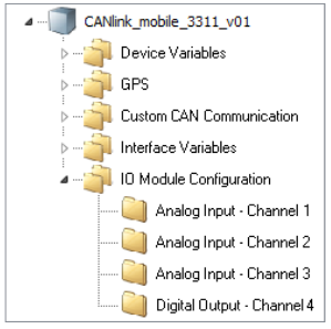
Figure 1: Input / Output Context Menu
Output Function
Define the settings for the output function under IO MODULE CONFIGURATION > DIGITAL OUTPUT - CHANNEL 4.
-
Select the object DIGITAL OUTPUT - CHANNEL 4.
-
In the CHANNEL CONFIGURATION list, select the configuration ON-OFF DIGITAL OUTPUT.
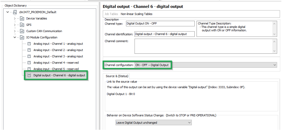
Figure 2: On - Off Digital Output
The following variables are available:
| Variable | Function |
|---|---|
| CHANNEL CONFIGURATION | Enable and disable the digital output. |
| BEHAVIOR ON DEVICE SOFTWARE STATUS CHANGE | Behavior on CANopen Mode STOP or PREOPERATIONAL. The output can retain its current value or be set to a defined value. |
Battery
Some types of the device are equipped with an integrated battery. The DEVICE VARIABLES > BATTERY object dictionary group contains the following variables:
| Variable | Function |
|---|---|
| BATTERY - CHARGE LEVEL | Current charge level (in_%) |
| BATTERY - VOLTAGE | Measured voltage (in_Volts) |
| BATTERY - CYCLE COUNT | Number of charge cycles so far |
| BATTERY - STATE OF HEALTH VALUE | Probable remaining capacity relative to nominal capacity (in %) |
| BATTERY - TIME TO EMPTY | Expected remaining time until full discharge (in Minutes) |
| BATTERY - FULL CHARGE CAPACITY | Probable capacity if fully charged (in mAh) |
| BATTERY - CURRENT | Current to or from the battery Value > 0: charging Value = 0: fully charged Value < 0: discharging |
| BATTERY - TEMPERATURE | Current temperature (in °C) |
| GO TO SLEEP VOLTAGE | Specifies the battery voltage threshold at which the device enters sleep mode. The value is defined in millivolts (e.g. 3500 = 3.5V, 3300 = 3.3V). |
Note
The GO TO SLEEP VOLTAGE device variable is not included in the default configuration and must be added manually if required.
Note
The integrated battery has a limited service life.
- Have the integrated battery replaced by our service department after 500 charging cycles. See Service and Support
Operation Time Counter
The device is equipped with an internal operation time counter.
The OPERATION TIME TOTAL object belongs to the DEVICE VARIABLES > I/O, SENSORS, DIAGNOSIS object dictionary group.
The operation time counter cannot be reset. The operation time counter runs as soon as the device is in Standard mode (not Sleep mode).
For detailed information on creating objects, see Creating Object Dictionary Groups and Objects.