Connectors
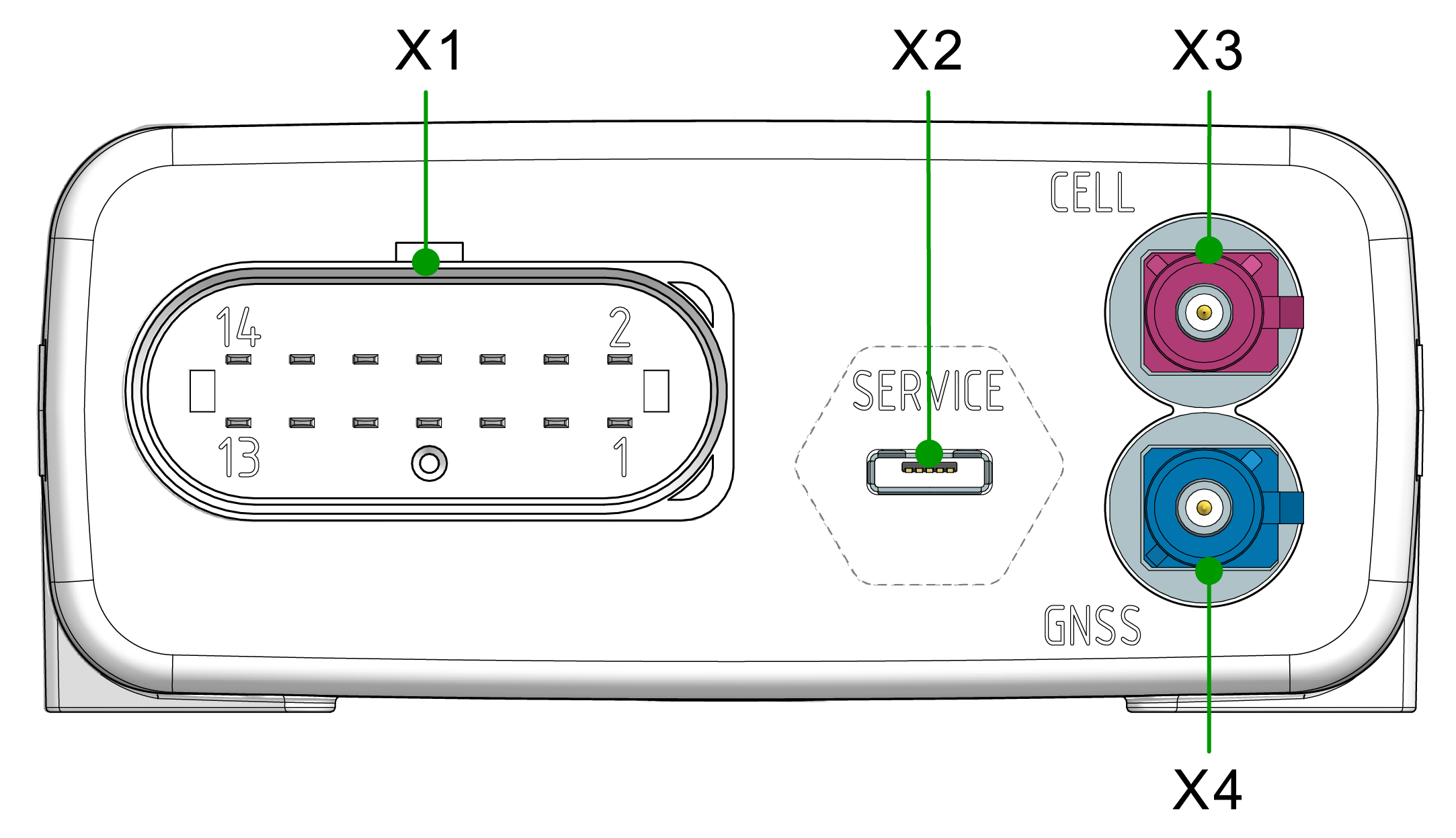
The device is equipped with the following connectors:
- X1 - main plug connector
- X2 - service interface/micro-USB port, type AB
- X3 - cellular antenna connector
- X4 - GNSS antenna connector
Note
Mating Cycles:
According to the manufacturer's information, the connectors are equipped for the following minimum number of mating cycles:
- Main plug connector: 10 cycles
- Fakra plug: 100 cycles
- Cellular Antenna Port: 100 cycles
- Service interface/Micro USB: 1000 cycles
If the minimum number of mating cycles is exceeded, individual parameters could lie outside those in the specification; meaning, the mating cycles can be carried out without quality problems at least for the minimum numbers of mating cycles. The basic function of the connectors remains intact.
Please be aware that the process of the CANlink mobile system integration is not designed for a high number of mating cycles.
Ideally - to minimize the mating cycles - the configuration should be finalized at the desk with the Starter Cable and not on the machine to avoid the device being plugged in repeatedly for each configuration update.
Optional CAN Interfaces:
The pin assignment shown in the following can vary depending on the type. The types 3611 and 3651 have no CAN2 and CAN3 interface.
Input specifications:
The analog inputs operate in a range of 0 VDC to 15 VDC.
Optionally, you can use the input as a digital input with a maximum voltage of 36 VDC. The digital output switches to supply voltage on terminal 30 and can only take a maximum load of 500 mA. Provide an external safeguard if this limit is not ensured by the external terminal 30 power supply.
Input terminal 15 detects "high" from a voltage of 5.5 V and "low" below a voltage of 2.3 V.
X1 - Main Plug Connector
Use the main plug connector to connect the device to the CAN bus and supply it with power. The I/O signals are integrated in the plug connector.
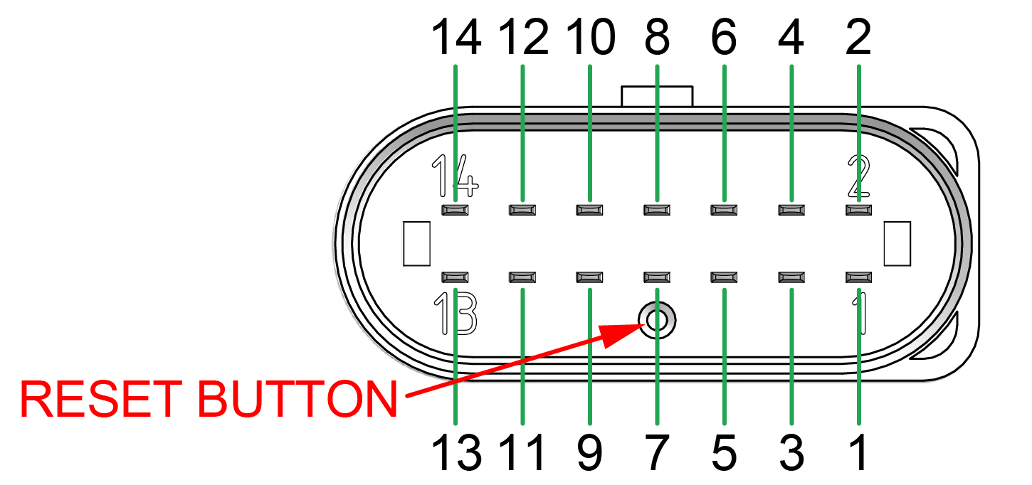
The main plug connector contains a reset button, see screenshot below.
The Reset button is required to complete local firmware updates or to switch the device off in the case of types with an integrated, rechargeable battery.
Pin assignment
| Pin | Designation | Description |
|---|---|---|
| 1 | Terminal 30 / VCC | Power supply |
| 2 | CAN3-Low | CAN, bidirectional |
| 3 | Terminal 31 / ground | Power supply |
| 4 | Analog input 1 | I/O input |
| 5 | Analog input 2 | I/O input |
| 6 | Analog input 3 | I/O input |
| 7 | Digital output | I/O output |
| 8 | Terminal 15 | Input (ignition_signal) |
| 9 | CAN3-High | CAN, bidirectional |
| 10 | CAN2-GND | - |
| 11 | CAN2-High | CAN, bidirectional |
| 12 | CAN2-Low | CAN, bidirectional |
| 13 | CAN1-High | CAN, bidirectional |
| 14 | CAN1-Low | CAN, bidirectional |
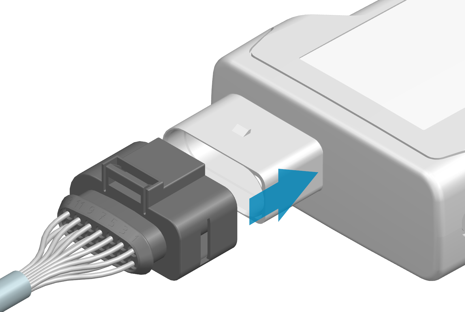
Connect main plug connector
Carefully connect the cable with the main plug connector. When connecting the plug, there must be a clear audible click. Then the lock is correctly engaged.
-
Preparation:
Ensure that all terminal contacts and pins on both sides of the plug connection are aligned correctly and are in a straight position. -
Mating process:
Insert the cable until you feel the locking mechanism engage.
A force of up to 140 N may be required. -
In case of resistance:
If an unusually high resistance occurs right at the start, interrupt the process and check the plug connection for:-
bent pins
-
blocked or misaligned contacts
-
Warning
Do not use any tools to force the connection. Damage to the contact carrier or the pins can impair the function.
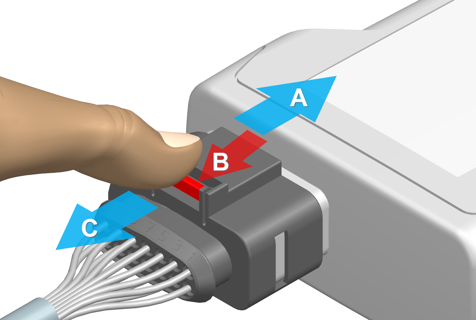
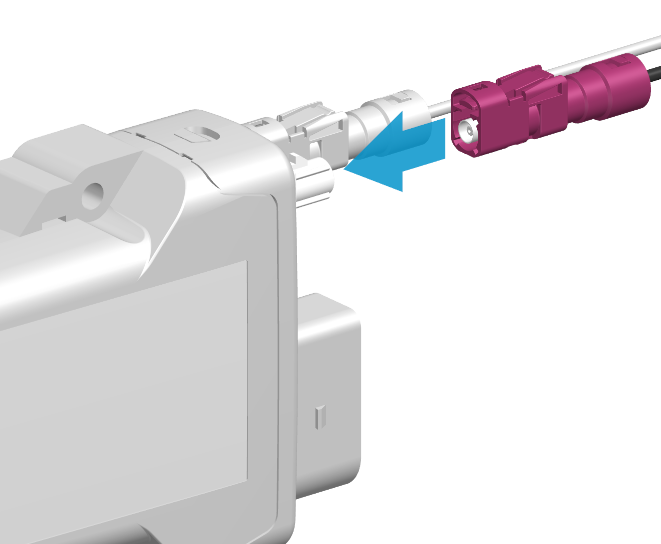
Disconnect main plug connector
To disconnect the main plug connector, remove it as shown in the following image:
-
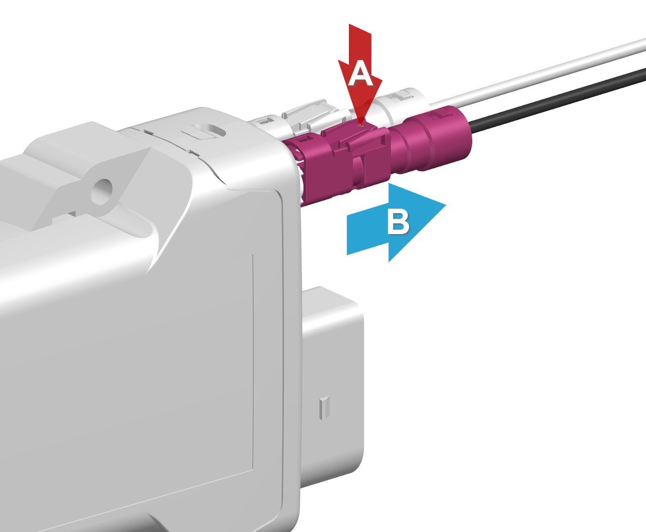
(A) Preparation: Push in the plug so that the latch is released.
-
(B) Hold the release mechanism: Pull and hold the release mechanism marked in red in the direction of the arrow to release the latch.
-
(C) Remove the plug: Pull out the plug completely with a maximum force of 90 N.
Depending on the installation situation, tools may be required for unlocking.
Please observe the directions and be aware of the risk of injury when using tools.
Warning
Make sure that no foreign objects or damaged parts block the unlocking mechanism. A clean and free plug connection is a prerequisite for safe disconnection.
X2 - Service Interface
Note
The firmware update via the Service Interface is no longer supported on devices running firmware version v4.0.0 or later. The deactivation is required to meet cybersecurity requirements in compliance with the RED directive. Devices shipped with firmware v4.0.0 and above no longer support this functionality.
The Service Interface is a micro-USB port. Use the micro-USB port to connect the device to a PC.
The micro-USB port is used for diagnoses as well as for bootloader and firmware updates:
- For instructions on how to perform diagnoses, see Diagnosis via micro-USB port.
To perform debugging or diagnosis, you need the cable USB cable, USB-A on micro-USB-B, 1.6 m (part number 136000138). See Software and Accessories.
Pin assignment
See the following overview for the pin assignment:
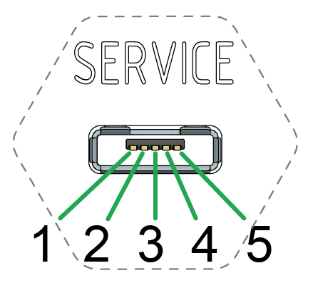
| Pin | Designation | Description |
|---|---|---|
| 1 | VBUS | Input |
| 2 | D- | Bidirectional |
| 3 | D+ | Bidirectional |
| 4 | ID | Input (0=boot_mode, 1/open=USB_device) |
| 5 | Ground | USB power supply / reference ground |
Risk of property damage
Pay attention that the USB plug is connected according to the correct assignment and without the need for any excessive force. Improper connection or excessive force can damage the USB port and render the device seal ineffective.
Note
Protection class IP6K7 is also ensured when no USB cable is connected.
Note
To protect the micro-USB port from soiling, make sure that the special Service Sticker is covering the USB port.
The device is self-powered. The micro-USB port corresponds with the USB 2.0 full speed device mode. The device is not supplied with power via the VBUS. Use of the ID pin does not comply with the USB standard because the micro USB port does not support USB-OTG. If a type-A USB cable is connected, the device remains in Bootloader mode.
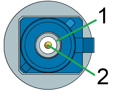
X3 - Cellular Antenna Connector
Use the cellular antenna connector (mobile radio connector) for types 3651, 3673, 3677 with external antennas (refer to the CANlink mobile 3600 Datasheet) to connect the device with an antenna to receive cellular signals.
Pin assignment
See the following overview for the pin assignment:
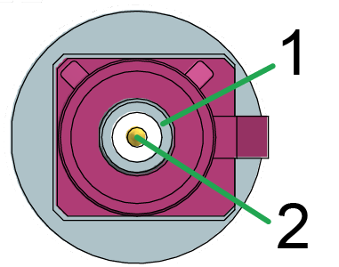
| Pin | Designation | Description |
|---|---|---|
| 1 | Ground | Signal ground /shielding |
| 2 | Signal | Cellular |
The connector is short-circuit-proof against Ground and detects the connection of an antenna in case that it has an integrated diagnosis resistance (10 kOhm).
Health hazards of radio-frequency energy
Risk of minor injury.
- Make sure the device is switched off during installation.
Note
The correct description for the corresponding mating connector is:
- FAKRA, D-coded, Claret Violet, Jack (Female)
- Manufacturer: Amphenol
- Part number: 3FA1-NDSJ-C01E0
Connect antenna cable
Carefully connect the antenna cable with the coded antenna connector.
-
Preparation:
Ensure that the coding within the socket is matching the coding of the connector and that all terminal contacts and pins on both sides of the plug connection are properly aligned and and are in a straight position. -
Insertion process:
Insert the connector until you feel the locking mechanism engage.
There must be a clear audible click. Then the lock is correctly engaged.
A force of up to 45 N may be required.
Disconnect antenna cable
-
(A) Hold the release mechanism:
Press and hold the release mechanism with your finger in the direction of the arrow to release the locking tab. -
(B) Pulling out the plug:
Pull out the plug completely with a maximum force of 30 N.
X4 - GNSS Antenna Connector
The GNSS antenna connector for types 3651, 3673, 3677 with external antennas (refer to the CANlink mobile 3600 Datasheet) is used to connect the device with an active antenna to receive signals from GNSS satellites.
Pin assignment
See the following overview for the pin assignment:
| Pin | Designation | Description |
|---|---|---|
| 1 | Ground | Signal ground /shielding |
| 2 | Signal | GNSS signal / supply voltage 3.3 V |
The GNSS antenna connector is supplied with a voltage of approx. 3.3 V and can supply active antennas with a maximum of 40 mA of power. The port is short-circuit-proof against Ground and detects an antenna is present from a current drawn greater than approx. 2 mA.
For connecting and disconnecting the antenna, please refer to Connect antenna cable and Disconnect antenna cable.
Health hazards of radio-frequency energy
Risk of minor injury.
- Make sure the device is switched off during installation.
Note
The correct description for the corresponding mating connector is:
- FAKRA, C-coded, Signal Blue, Jack (Female)
- Manufacturer: Amphenol
- Part number: 3FA1-NCSJ-C01E0