CAN logging Example 2 -- Logging specific data bytes under certain conditions
In this example, specific data bytes are logged under defined conditions.
Data bytes 2 ... 5 and 8 of the CAN messages received are logged when the engine speed (data_bytes_4_and_5) changes by ± 500 rpm, or every 10 minutes.
A received CAN message is processed with the following functions:
-
Mapping
-
Jobs
-
Logging
VARIABLES
If you want to log data under defined conditions, you need certain variables for checking values.
These variables belong to the INTERFACE VARIABLES object dictionary group.
Create the INTERFACE VARIABLES object dictionary group.
In the INTERFACE VARIABLES object dictionary group, create four new INTERFACE VARIABLE objects.
✓ The LIST OF INTERFACE VARIABLES window opens.
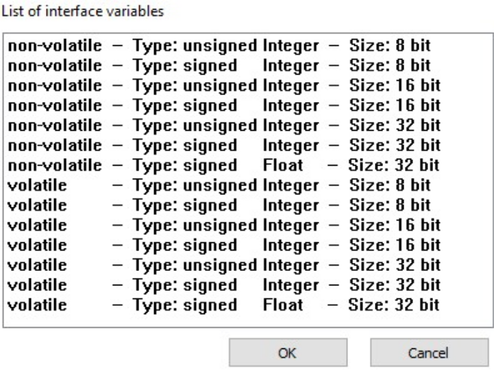
Select the first INTERFACE VARIABLE object according to the following table.
| Designation | Type | Sign | Size |
|---|---|---|---|
| volatile U8 Trigger | volatile | unsigned | 8 bits |
| volatile S32 Engine Speed new | volatile | signed | 32 bits |
| volatile S32 Engine Speed old | volatile | signed | 32 bits |
| non-volatile U16 threshold value | non-volatile | unsigned | 16 bits |
Click on the OK button.
✓ The INTERFACE VARIABLE object with the selected settings is created.
Repeat this procedure for the other three INTERFACE VARIABLE objects.
Rename the four INTERFACE VARIABLE objects according to the table.
Define a threshold value for the NON-VOLATILE U16 THRESHOLD VALUE object.
✓ The four INTERFACE VARIABLE objects are displayed
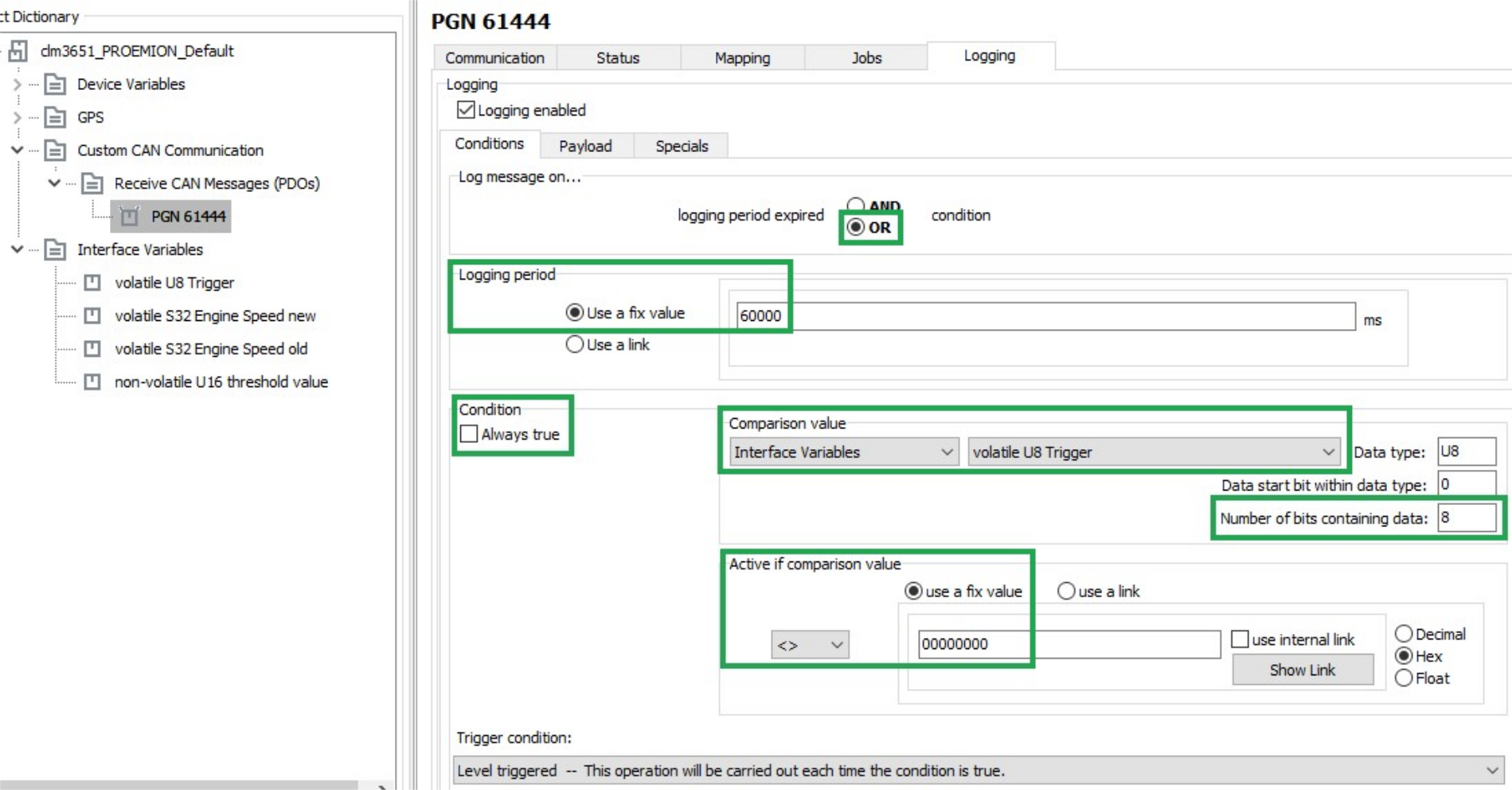
LOGGING - CONDITIONS
Define the following settings for the PGN 61444 object.
Select the LOGGING tab.
Select the CONDITIONS tab.
Make the following settings.
| Description | Selection | Function |
|---|---|---|
| LOG MESSAGE ON | OR |
The data is logged when timeout is reached OR the condition is met. |
| LOGGING PERIOD | Use a fixed value (600000) |
Duration of the logging interval in milliseconds. |
| CONDITION / ALWAYS TRUE | not set | The data is logged depending on the result of the check. |
| COMPARISON VALUE | volatile U8 Trigger |
Logging depends on the VOLATILE U8 TRIGGER variable. |
| NUMBER OF BITS CONTAINING DATA | 08 |
All 8 bits of the variable are compared with COMPARISON VALUE. |
| ACTIVE IF COMPARISON VALUE | <>0 |
Data is only logged if the variable VOLATILE U8 TRIGGER is not equal to 0. |
| TRIGGER CONDITION | Level triggered - This operation will be carried out each time the condition is true. | Logging is enabled as long as the variable VOLATILE U8 TRIGGER is not equal to 0. |
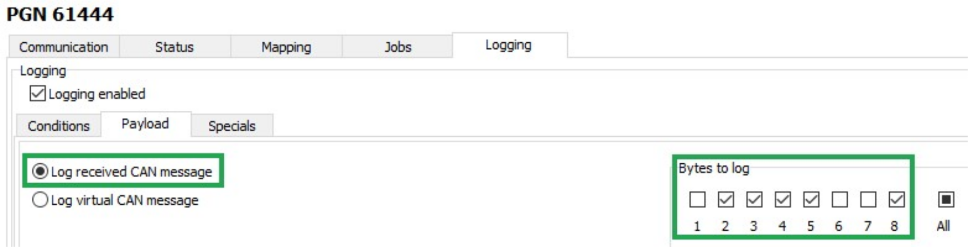
PAYLOAD
Select the PAYLOAD tab.
Define the following settings.
| Description | Selection | Function |
|---|---|---|
| LOG RECEIVED CAN MESSAGE | Set | Log data of the receive CAN message. |
| BYTES TO LOG | 2 ... 5 and 8 | Logging selected data bytes |
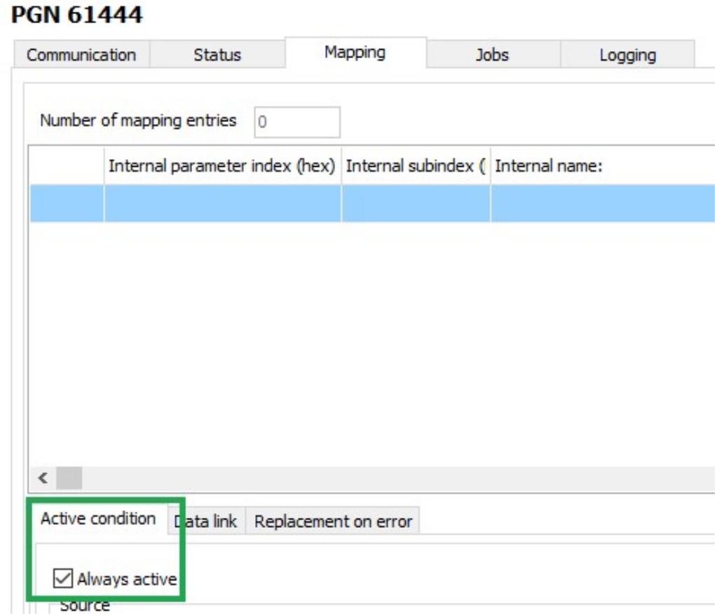
MAPPING - ACTIVE CONDITION
During mapping, data is copied from the CAN message to variables. You can then process the copied data in the device and perform calculations.
Select the MAPPING tab.
Select the ACTIVE CONDITION tab.
Define the following settings.
| Description | Selection | Function |
|---|---|---|
| ALWAYS ACTIVE | Set | Mapping always takes place without conditions. |
DATA LINK
Select the DATA LINK tab.
Define the following settings.
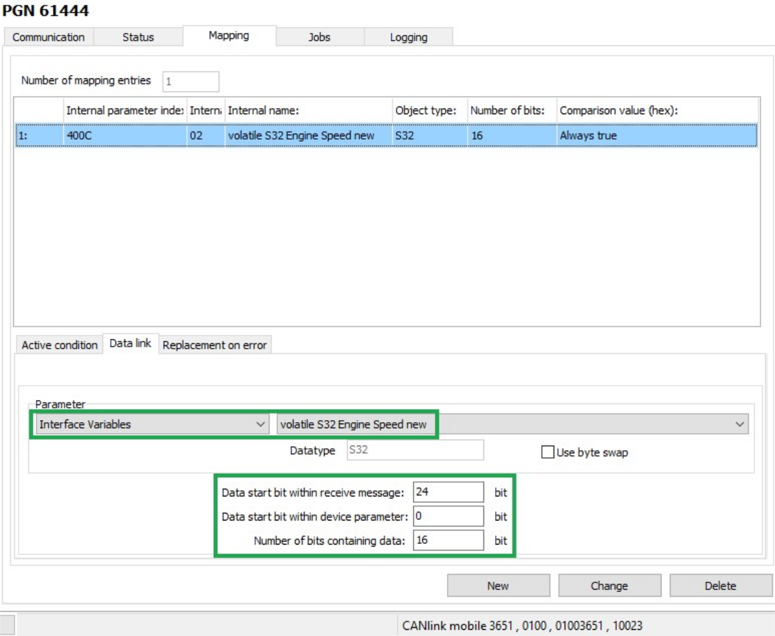
| Description | Selection | Function |
|---|---|---|
| PARAMETER | volatile S32 Engine Speed new | The data is written to the VOLATILE S32 ENGINE SPEED NEW variable. |
| DATA START BIT WITHIN RECEIVE MESSAGE | 24 bits | The data used starts with bit 24 (from_the_4th_byte). |
| DATA START BIT WITHIN DEVICE PARAMETER | 0 bits | The data used begins from bit 0 |
| NUMBER OF BITS CONTAINING DATA | 16 bits | The data used has 16 bits (2_bytes). |
Click on the NEW button to create the mapping entry.
✓ The mapping entry is adopted in the table.
✓ The data is copied into the internal variable on reception of a CAN message.
JOBS
Every time a CAN message is received, jobs are performed after mapping and before logging.
In the JOBS tab, configure the calculation operations you need for your job.
For the example configuration, you need two jobs with the function CALCULATE PARAMETER VALUE FUNCTION. With this function, you perform calculation operations and overwrite interface variables with calculated values.
JOB 1
With the first job, you check whether the current speed is above or below the threshold value. If one of these two cases applies, the VOLATILE U8 TRIGGER variable should be set to the value 1. This triggers logging of the CAN message.
| Variable | Type | Name/value |
|---|---|---|
| A | S32 | volatile S32 Engine Speed new |
| B | S32 | volatile S32 Engine Speed old |
| C | U16 | non-volatile U16 threshold value |
| D | S32 | volatile S32 Engine Speed new |
| E | S32 | volatile S32 Engine Speed old |
| F | U16 | non-volatile U16 threshold value |
The buttons for entering the calculation operations have the following functions:
| Buttons | Description |
|---|---|
 |
C = Clear: Deletes the entire calculation operation |
CE = Clear Entry: Only deletes the last symbol entered |
|
 |
Add variables to the calculation operation.Click on the button to open a window. Assign fixed values, interface variables or device variables to the variables. After you have defined a variable, the display on the button switches to the next variable. The selected variables are listed under LIST OF OPERANDS, including their values and types. |
 |
Basic calculation types (addition, subtraction, multiplication, division) |
   |
NOTE: Before applying these operations any input value is cast to unsigned integer type! |
and = arithmetic (bitwise) AND operation. |
|
or = arithmetic (bitwise) OR operation. |
|
xor = arithmetic (bitwise) XOR operation. |
|
| On integer numbers, the operation is performed bitwise. If the operators only contain the values 0 or 1, the operation can be considered a logical calculation. | |
not = logical NOT operation. |
|
| If the operand is 0, the expression evaluates to 1. If the operand is unequal to 0, the expression evaluates to 0. | |
| WARNING: Do not apply these operators on floating-point numbers! | |
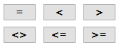 |
Comparative value (equal_to, less_than, greater_than, not_equal_to, less_or_equal_to, and_greater_or_equal_to). The expression evaluates to 1 when the comparison is true. The expression evaluates to 0 when the comparison is not false. |
 |
Brackets |
Note
The calculation formulas are evaluated from left to right. Mathematical priority rules are not observed!
Define the priority calculations in the formula using brackets
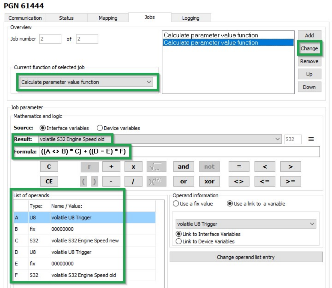
JOB 2
In the second job, you replace the value of the VOLATILE S32 ENGINE SPEED OLD variable with the value of the VOLATILE S32 ENGINE SPEED NEW variable as soon as the VOLATILE U8 TRIGGER variable has the value 1. This updates the speed from which the deviation should be detected.
This updates the speed from which the deviation should be detected.
-
Select the JOBS tab.
-
In the CURRENT FUNCTION OF SELECTED JOB list, select the function CALCULATE PARAMETER VALUE FUNCTION.
-
In the RESULT list, select the trigger VOLATILE S32 ENGINE SPEED OLD.
-
Using the buttons in the MATHEMATICS AND LOGIC section, enter the calculation operations
((A <>_B) * C) + ((D # E) * F). -
Click on button A.
!!! note If you click on a placeholder (e.g. A), the window INPUT OPERAND INFORMATION OR OPEN A NEW OPERATION opens. You can find the allocation of the variables for this example in the table below.
-
Click on the variable in the list that you want to allocate the placeholder to.
-
Allocate the following variables to the placeholders:
Variable Type Name/value A U8 volatile U8 Trigger B fix 00000000C S32 volatile S32 Engine Speed new D U8 volatile U8 Trigger E fix 00000000F S32 volatile S32 Engine Speed old : Variables - Job 2 -
Click on the NEW button when you have entered the calculation operations completely.
-
Click on FILE > SAVE in the menu.
-
Load the configuration to the device. See Chapter Loading the configuration to the device.
✓ You have completed the configuration for logging specific data bytes.