Configuring the Device
The device is delivered with a basic configuration. Customize the configuration to your purposes by defining the CAN messages to be logged.
You load new configurations to the device via CAN interface or the DataPortal. The configuration described below uses the CAN interface.
For more detailed information on configuration using the DataPlatform, see chapters Configuration update and Safe Remote Updates Guideline.
Connecting the Device to the PC
To configure the device with a PC, you must connect it with the PC.
Note
In the following example, the PCAN-USB, included in the Launch Kit, is used. You must first install the PEAK PCAN-USB driver to use the PCAN-USB for the configuration of the device, see Installing Software.
-
Connect the PCAN-USB - CAN/USB Interface to a USB Port on the PC.
-
Place a CAN bus termination on the D-Sub connector of the PCAN-USB - CAN/USB Interface.
-
Use the cable Starter cable for main plug connector with the CAN1 or CAN2 plug to connect the CANlink mobile to the CAN-bus termination of the PCAN-USB - CAN/USB Interface.
-
Use the cable Starter cable for main plug connector and the power supply unit from the launch kit to connect the CANlink mobile to the power grid.
✓ The ON LED lights up in constant green.
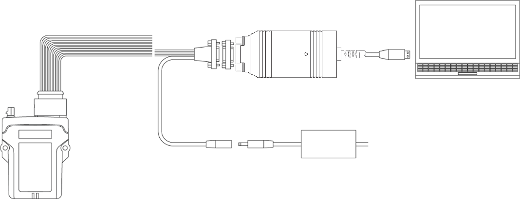
Image of PCAN-USB copied from PCAN-USB User Manual.
Note
Please be aware that the CANlink mobile 3600 is not equipped with an integrated CAN bus termination resistor.
The displayed laboratory setup above will work with just one CAN bus termination resistor.
When doing the system integration at the intended machine, it must be ensured that the CAN bus is terminated with a CAN bus termination resistor of 120 Ohm at each end of the CAN bus line.
Also refer to CAN Bus Termination.
Making Communications Settings
Before you can start using the device, you must define the communication settings once.
Note
Install the USB driver pack from the Download Center before connecting the device to a PC using a USB port. See Installing Software.
-
Connect the device to a PC. See Connecting the Device to the PC.
-
Start the Proemion Configurator software.
-
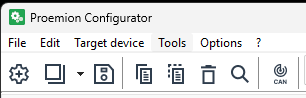
To open the COMMUNICATIONS SETTINGS, in the menu bar click the
 Communication Gateway icon.
✓ The window COMMUNICATION SETTINGS opens.
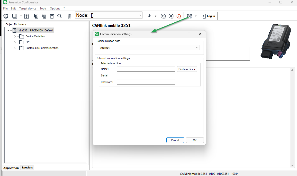
Figure 2: Communication Settings -
In the Communication path, select PEAK PCAN-USB as the device.
-
In the PEAK PCAN-USB settings, select Baudrate: 250 kbit/s.
✓ You have completed the communication settings.
Node Scan
Perform a node scan to check the connection.
-
Connect the device to a PC. See Connecting the Device to the PC.
-
Start the Proemion Configurator software.
-
Click on TOOLS > NODE SCAN in the menu. Alternatively, you can click on the button in the toolbar.
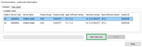
✓ The COMMUNICATION-NODE SCAN INFORMATION window opens.
-
Click on the START NODE SCAN button.
✓ The CAN devices connected are displayed with their CAN open Node-IDs, product codes, and information on hardware and software versions.
-
Select the device you want to configure.
-
Click on the CLOSE button.
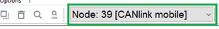
✓ The Node-ID and the designation of the selected device are shown in the toolbar.
Customizing the demo configuration File
-
Connect the device to a PC. See Connecting the Device to the PC.
-
Start the Proemion Configurator software.
-
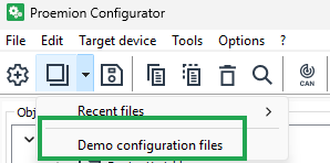
Click on the arrow in the toolbar and select DEMO CONFIGURATION FILES.
✓ The OPEN DOD FILE window is shown.
-
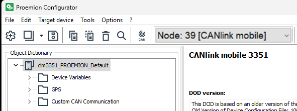
Navigate to the correct folder for your device (in_this_example_CANLINK_mobile_3651) and open one of the files with the extension *.DOD.
✓ The selected demo configuration file is loaded.
-
Click on FILE > SAVE AS... in the menu.
-
Save the file under a different name to avoid overwriting the original file.
Tip
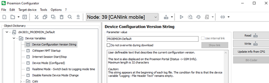
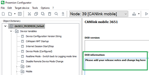
You can enter a designation for the configuration in the DEVICE CONFIGURATION VERSION STRING object of the DEVICE VARIABLES.
This text is displayed as a DOD version in the DataPortal under Communication Unit Details and in the configuration version history.Use an unequivocal designation for every configuration. Differentiate between various versions of a configuration by adding a version number.
-
Adjust the configuration file to your requirements. See Proemion Configurator.
-
Customize the DEVICE CONFIGURATION VERSION STRING
-
Enter notes on the adaptations completed in the DOD INFORMATION field.
Note
Save the file with the current configuration in case you need the configuration again later.
It is not possible to read off the current configuration from the device.
Note
If there is no Demo Configuration file available, you must create a new configuration for the device.
The Object Dictionary Groups and DEVICE VARIABLES required must be set-up manually in this case. See Creating Object Dictionary Groups and Objects.
Loading the Configuration to the Device via CAN Interface
After you have created your own configuration file, load the configuration to the device.
-
Connect the device to a PC. See Connecting the Device to the PC.
-
Start the Proemion Configurator software.
-
Define the communication settings for the PCAN-USB - CAN/USB Interface device. See Making Communications Settings.
-
Complete a Node Scan and select the CAN node of the corresponding device.
-
Choose FILE > OPEN... from the menu.
-
Open the desired configuration file.
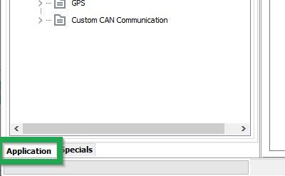
-
Select the APPLICATION tab.
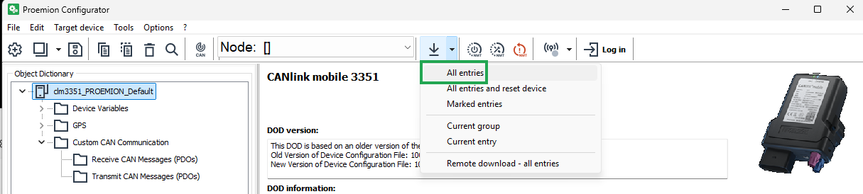
-
Click on the DOWNLOAD ALL ENTRIES button in the toolbar.
✓ The DOWNLOAD DATA TO DEVICE window is shown.
-
Click on the START button to start the download to the device.
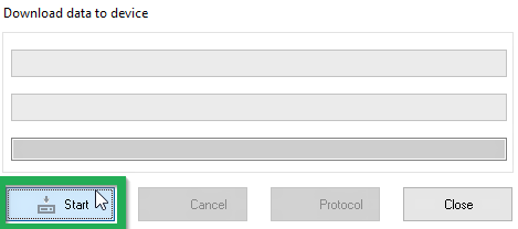
-
Wait until the download is completed.
Note
Loss of function or configuration.
Disconnection from the power supply during the update process can lead to a loss of the function or the configuration.- Do not disconnect the power supply during updating.
✓ The configuration has now been installed on the device.
-
Click on the RESET CAN NODE button.
-
If you have changed the CAN baud rate (DEVICE CAN BAUD RATE) in the configuration, check whether the configuration has been correctly adopted.
-
Change the CAN baud rate of the PCAN-USB - CAN/USB Interface. See Making Communications Settings.
-
Perform a Node Scan to check the connection.
✓ The ON LED lights up in constant green.
✓ The STATUS LED flashes green, then lights up in constant green.
Note
For further information on how to perform a remote configuration update, please refer to chapter DataPlatform