CANlink wireless 4000 Device Manual
Preamble
Preamble
In the following chapter you find general information on the company and on the device manual.
Legal Notice
All brands and trademarks named in this document and possibly protected by third-party rights are subject without limitation to the terms of the valid trademark law and intellectual property rights of their respective registered owner.
You can find a list of the free-source and open-source software as well as copyright notes, license texts and, if applicable, the relevant source code on our website under the link: Free & Open Source Software Observe all local and regional laws and provisions as well as the safety instructions contained in this document.
Contact
Proemion GmbH
Donaustr. 14 36043 Fulda, Germany
Phone: +49 661 9490-0
Fax: +49 661 9490-111
info@proemion.com
Proemion Corp.
US Subsidiary 241 Taylor St., Suite 301
Dayton, Ohio 45402, USA
Phone: +1 937 558 2211
Fax: +1 937 641 8787
info-dayton@proemion.com
Proemion Ltd.
373 Gangnam-daero Seocho-gu
Seoul, 06621, South Korea
Phone: +82 2 6080 9490
Fax: +82 504 484 9490
info-seoul@proemion.com
Website: Proemion
About This Manual
This document is part of the product and provides important information on the intended use, safety, installation, and operation of the devices described below. The document is intended for qualified technicians and electricians with advanced knowledge in electrical engineering and field bus systems, allowing them to estimate the risks and hazards of operating the device and to integrate it into systems with components of other manufacturers.
Safety Levels
The safety levels have the following meanings:
Danger
Severe injury or death. Probability: very high
Warning
Severe injury or death. Probability: possible
Note
Indicates notes and information
Other information
Tip
Valuable information
Tasks
Tasks are structured as follows:
- Aim of the task
- Prerequisites for the described task.
- Step 1.
-
Step 2.
Result of correct performance of the task.
-
Step 3.
Lists
Lists are indicated as follows.
- List item
Notations
The following notations are used in this document:
| Designation | Representation |
|---|---|
| Keys, commands, messages | Keys, commands, messages |
| Navigation in menus, functions of the user interfaces, file paths | FILE > SAVE > Click OK button |
| Accessories | Cable, adapter |
About the Device
Important Device Information
More technical information can be found in the Annex.
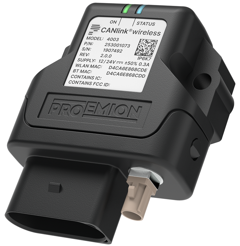
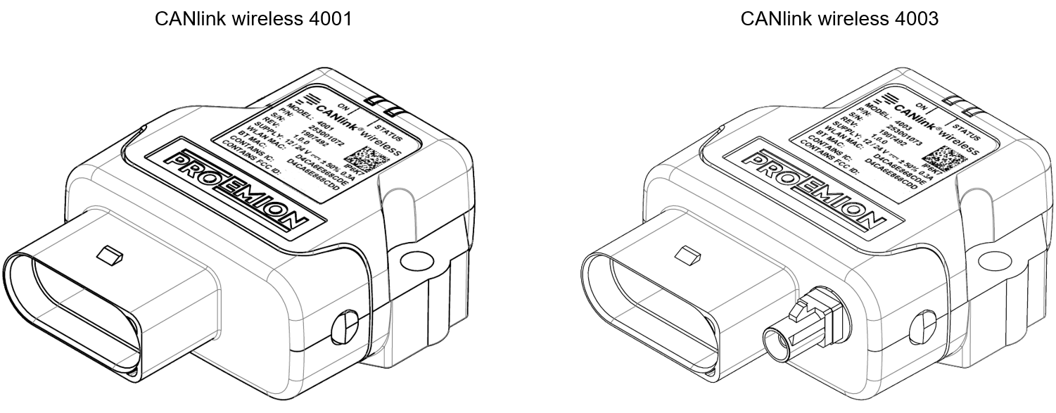
Device Elements
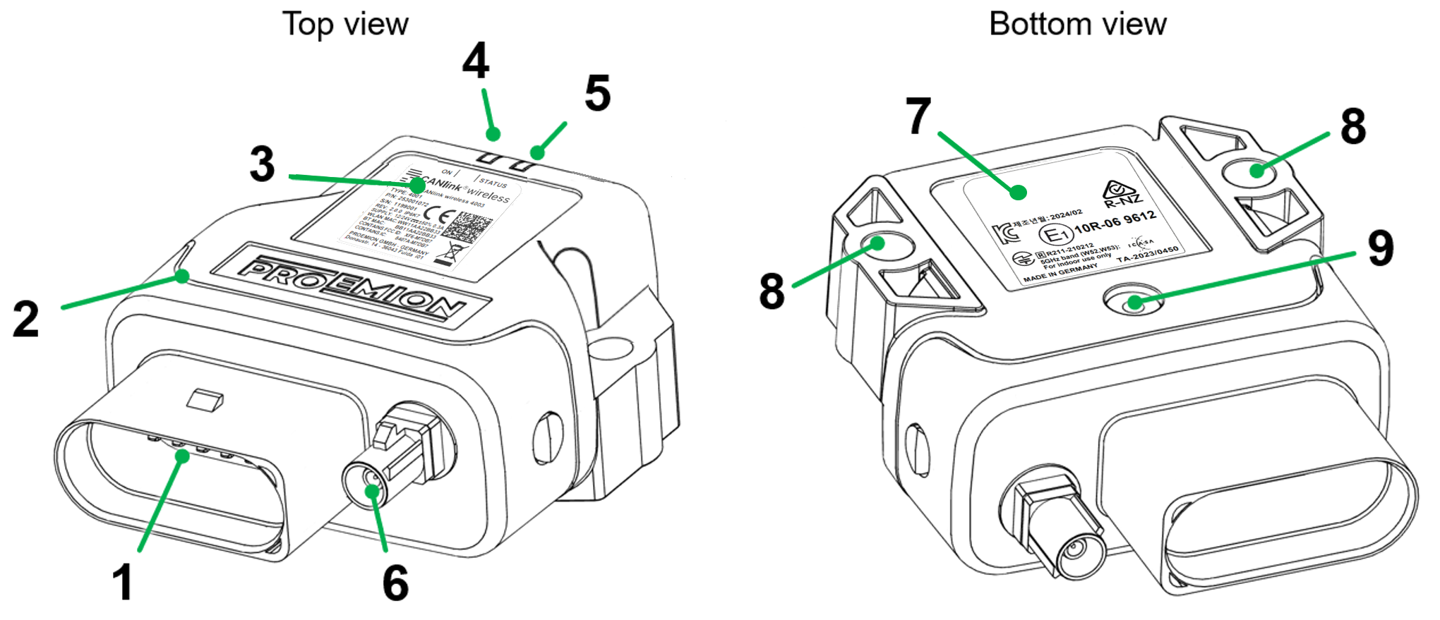
| # | Item |
|---|---|
| 1 | Main plug connector |
| 2 | Housing |
| 3 | Type label top |
| 4 | LED On |
| 5 | LED Status |
| 6 | RF antenna connector |
| 7 | Type label bottom |
| 8 | Mounting holes |
| 9 | Pressure compensation element |
Note
The CANlink wireless 4001 does not feature an external antenna connector. The antenna is integrated in the device.
Type Label
The type label on top provides the following information:
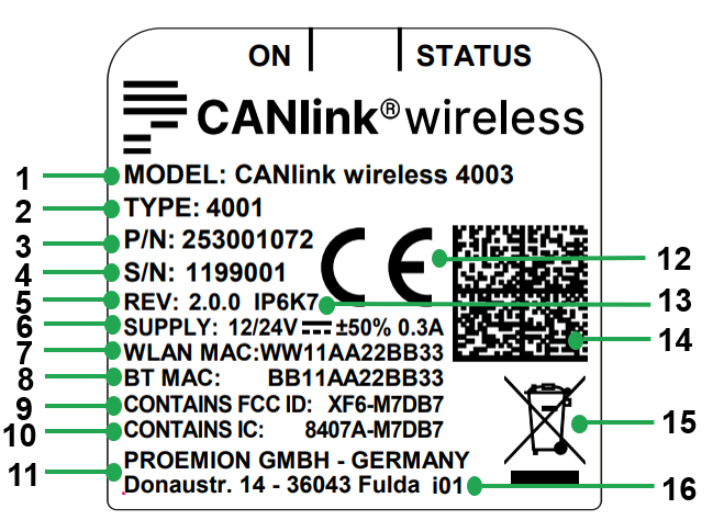
| # | Item |
|---|---|
| 1 | Model designation |
| 2 | Type |
| 3 | Part number |
| 4 | Serial Number |
| 5 | Hardware version |
| 6 | Power supply |
| 7 | WLAN MAC address |
| 8 | Bluetooth MAC address |
| 9 | FCC-ID |
| 10 | IC-ID |
| 11 | Manufacturer address |
| 12 | CE mark |
| 13 | Protection class |
| 14 | Traceability code |
| 15 | Disposal symbol |
| 16 | Product Change Index |
The type label at the bottom provides the following information:
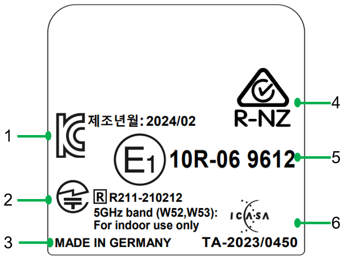
| # | Item |
|---|---|
| 1 | KC certification mark |
| 2 | TELEC certification mark |
| 3 | Country of origin |
| 4 | ACMA/R-NZ certification mark |
| 5 | ECE certification mark |
| 6 | ICASA certification mark |
Note
Use of solvents on the product label can remove or destroy product information.
Keep solvent-containing substances away from the label!
Loss of connectivity at devices with internal antenna
Please do not stick additional labels onto the device. Depending on the nature of the material, these stickers can severely impair the signal quality.
Note
The device's type label contains important information.
Do not remove the type label.
Traceability code
The traceability code contains the following information. Example:
253001072000000000001907492(W)D4CA6E868CDE(B)D4CA6E868CDD
| Item | Description |
|---|---|
| 9-digit part number: | 253001072 (P/N depends on Type) |
| Serial number 0-padded: | 1907492 |
(W) followed by the WLAN MAC Address: |
D4CA6E868CDE |
(B) followed by the Bluetooth MAC Address: |
D4CA6E868CDD |
Intended Use
The device provides access to the CAN data of a vehicle or machine in various operating modes:
CAN-CAN Bridge: wireless transmission of CAN data between CANlink wireless devices, e.g. as a substitute for CAN cables in drag chains or with remote control units.
-
CAN-Bluetooth Interface: wireless transmission of CAN data to a Bluetooth terminal device.
-
CAN-Wi-Fi® Interface: wireless transmission of CAN data to devices in the wireless network.
-
CAN-BLE Interface: wireless transmission of CAN data to a BLE terminal device, such as a phone, tablet or PC.
In Interface mode, CAN data can be transmitted to other Wi-Fi®/Bluetooth devices such as PCs, smartphones, and tablets for displaying and evaluation of data.
The device is suitable for use in mobile and stationary systems for industry, small business, agricultural, construction and forestry machinery.
Failure of safety-related functions due to deficient data transmission
Severe injury or death. The device operates using radio signals and is not authorized for use in safety-related applications. Insufficient Wi-Fi® availability, interference or malfunctioning of the device can cause faulty data transmission. Because of this, data transmission cannot be always guaranteed and under all conditions.
- Never operate the device in machines or applications where life depends on the fault-free operation of this device.
- Never rely solely on wireless devices for essential communications.
- The device is designed to be used in systems which must be checked for conformity with the respective valid legal requirements prior to putting into operation. The integrator of the device is responsible for ensuring that the device complies with all regional regulations and requirements.
- The device must only be put into operation by qualified technicians and electricians with advanced knowledge of electrical engineering and fieldbus systems
The CANlink® wireless 4000 series can be used in environments that require protection class IP6K7.
Note
Protection classes IP6K7 are only guaranteed when all connectors of the device are equipped with their corresponding connector plugs and the and the device is installed in accordance with the hints from chapter Mounting the Device.
Only use the device within the permitted temperature range and the other parameters specified in the technical data. Any use other than that described under "Intended use" is considered unintended use.
Misuse
The device does not comply with Directive 2014/34/EU and may not be used in potentially explosive areas.
Qualified Personnel
The device must only be put into operation by qualified technicians and electricians with advanced knowledge of electrical engineering and fieldbus systems. The specialist personnel must know the contents of this manual and always have access to it.
Note
Risk of Property damage.
A defective device must be inspected and repaired by a trained {company_name} service technician.
Do not open the device housing by yourself.
Note
Risk of Property damage.
Device is not installed in accordance with the setup requirements and permitted environmental conditions.
- The system integrator is responsible to install the device according to the specification and take corrective action in regards mechanical protection against soiling, water penetration and vibration.
- If necessary, install external protection shields. For example, an additional housing to protect the device from jet water.
- Install the device according to the recommended mounting position.
- Ensure that the cable management fulfils the required mechanical protection, insulation from vibration and strain.
Conformity
For details of the corresponding approval tests, see Certification and Qualification The device meets the requirements of the following standards and legal requirements:
 |
CE Compliant This device complies with the directives, standards and normative documents listed in Certification and Qualification |
 |
FCC Compliant This device complies with Part 15 of the FCC rules. Operation is subject to the following conditions: The device may not cause harmful interference. The device must accept any interference received, including interference that may cause undesired operation. See Certification and Qualification |
 |
E1 Compliant This device has been approved by the KBA (Kraftfahrtbundesamt, Federal Office for Motor Traffic) as compliant with Regulation No. 10. See Certification and Qualification |
 |
TELEC compliant for Japan This device is certified under business law  AD190040201 and radio law AD190040201 and radio law  R201-190133. The Model CANlink wireless 4003 is additionally certified under radio law R211-210212 and utilizes the 5GHz band (W52, W53): For indoor use only. R201-190133. The Model CANlink wireless 4003 is additionally certified under radio law R211-210212 and utilizes the 5GHz band (W52, W53): For indoor use only. |
 |
ISED Compliant This device complies with the directives, standards and normative documents listed in Certification and Qualification |
 |
KC compliant for Korea 기자재의 명칭: 특정소출력무선기기(무선데이터통신시스템용 무선기기) 인증번호: R-C-pRo-CLW4003 적합성 평가를 받은 자의 상호: 프로이미온 유한회사 제조자/제조국가: Proemion GmbH / 독일 |
Note
For more information about compliance, see Certification and Qualification.
Should you have any questions, simply contact the support team. See Chapter Service and Support.
Available Model and Types
The available Types differ only in the external antenna connector:
- Type
4001has an internal antenna - Type
4003has a connector for an external antenna
With either device, you can transmit and receive CAN data via a Wi-Fi; Bluetooth, or BLE connection.
| Model | Type | Part # | Antenna | CAN | Wi-Fi | Bluetooth | BLE |
|---|---|---|---|---|---|---|---|
| CANlink wireless 4003 | 4001 | 253001072 | internal | 2 | ✅ | ✅ | ✅ |
| CANlink wireless 4003 | 4003 | 253001073 | external | 2 | ✅ | ✅ | ✅ |
There are also two major roles the CANlink® wireless 4000 can be configured in:
-
CAN-Wireless Interface:
The CAN-Wireless Interface transmits CAN data to other Wi-Fi or Bluetooth-capable devices on which CAN data is logged and evaluated. -
CAN-CAN Bridge:
The CAN-CAN Bridge replaces a CAN cable and transmits the CAN data between two CANlink wireless devices.
Note
You can find the Wi-Fi standards and Bluetooth profiles supported in chapter Interfaces.
Pre-configured Bluetooth Bridge Sets
There are two bridge sets available.
Both sets are composed of two devices pre-configured as a Bluetooth point-to-point bridge, with the devices marked as Client and Server.
By default:
- the CAN baud rate is 250 kBit/s
- the CANopen stack is enabled during connection
- there is a randomly assigned 15 byte Bluetooth PIN
- the receive objects are configured to forward all 11- and 29-bit ID CAN messages except the corresponding COB ID of the SDO Server.
The sets differ only in that one is the type 4001 with internal antenna, and the other is the type 4003, with external antenna.
| SAP Part Number / Ordering code | Material short text | Antenna |
|---|---|---|
| 253001193 | CANlink wireless 4001 Bridge | Internal |
| 253001194 | CANlink wireless 4003 Bridge | External |
Scope of Delivery
-
CANlink® wireless 4000
-
Leaflet with instructions for downloading the documentation
-
Simplified CE Declaration of Conformity
Launch Kit
For the initial setup of the device, an additional launch kit (part number 253000187) with the following components is available for ordering:
| Material | Qty |
|---|---|
CLW4K Starter Cable 6open 2dsub 1pw 2m136000197 |
1 |
Cable MTII 14pin code1 open 2m136000198 |
1 |
| ANT WLDB DA 2M0 FAKRA-I FA (Antenna) |
1 |
| PCAN-USB - CAN/USB Interface | 1 |
| CAN bus terminator D-Sub/D-Sub, 120Ω | 1 |
| Power supply unit | 1 |
| Mounting kit M6 Enclosure GH0806 | 1 |
| CANlink Connector Kit | 1 |
The launch kit contains all components and accessories that are needed for the initial configuration, mounting and operation of a CANlink® wireless 4000 device.
It allows the examination of different mounting and connection options.
Use Cases
Depending on the use case (number of devices used) and the device types (internal/external antenna), you may need more than one launch kit for an initial setup.
The use cases can be: setting up a bridge between two pieces of equipment or setting up a wireless connection for analysis.
Minimum requirements
For every device you must have at the least the connector.
For the 4003 type of the CANlink® wireless 4000, you additionally need the antenna. Both components are included in the launch kit.
A launch kit contains 3 types of cables for the main plug connector:
-
Starter Cable / Main Plug Connector:
Complete cable including the main plug connector and other connectors.
Ideal for testing on the desk. -
Starter cable for main plug connector, Individual wires open:
Cable including the main plug connector and open wires to be connected to the machine's cable harness.
Ideal for testing on the machine.
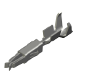
Proemion offers the Connector Kit containing the main plug connector and contacts in order to build a custom cable.
If you want to connect the devices to a machine, you either need several connectors with open wires or the Connector Kit for custom mounting.
Accessories
The software can be downloaded from our Download Center under: 03_Proemion Tools Software > 01_Software
| Material | SAP Part Number / Ordering code |
|---|---|
| CLW4K Starter Cable 6open 2dsub 1pw 2m | 136000197 |
| Cable MTII 14pin code1 open 2m | 136000198 |
| ADAPTERKABEL CANLINK 14P-M12 5P 30cm This supports the replacement of a CANlink® wireless 3000 by CANlink® wireless 4000 hardware. |
136200001 |
| CANlink Connector Kit Refer to Connector Kit Datasheet for further information |
132600031 |
| ERGOCRIMP HAND TOOL 539635-1 without die-set. This is the Hand Tool required for assembling the Connector Kit |
Direct order at supplier |
| ERGOCRIMP DIE SET for MICRO Timer and Micro Timer (SWS) 539663-2 Micro Timer | Direct order at supplier |
| Mounting Kit M6 Enclosure GH0806 | 141000021 |
| ANT WLDB DA 2M0 FAKRA-I FA | 157000126 |
| Power supply US EU UK AU 24V/0.83A/20W | 257004007 |
| CAN bus terminator D-Sub/D-Sub CANterm 120 | 157000033 |
| PCAN-USB - CAN/USB Interface | 257001041 |
| Launch Kit | 253000187 |
Starter Cable
The cable CLW4K Starter Cable 6open 2dsub 1pw 2m (part number 136000197) is equipped with the following connectors and open individual wires:
- 1 micro timer II socket,14-pin, female
- 2 D-sub, 9-pin, female (CAN1 and CAN2)
- 1 power connector
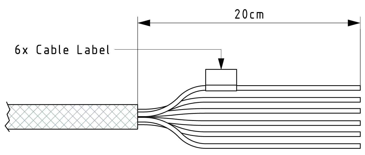
Starter cable: Individual wires
The open-end connectors are numbered on the strand ends.
The polarity also applies for the following cable:
- CLW4K starter cable 6 open, 2 D-Sub, 1 pw, 2 m (part number
136000197)
| Designation | Color | Description |
|---|---|---|
| Terminal 31 / ground | Green | Power supply |
| Analog input 1 | Yellow | I/O input |
| Analog input 2 | Gray | I/O input |
| Not used | ― | ― |
| Digital output | Blue | I/O output |
| Terminal 15 | Red | Input (ignition signal) |
Starter cable: Power supply cable
| Pin | Designation | Color | Description |
|---|---|---|---|
| 1 | Terminal 31 / ground | Green | Power supply |
| 2 | Terminal 30 / VCC | White | Power supply |
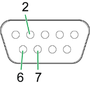
Starter cable: D-Sub connector (CAN1)
| Pin | Designation | Color | Description |
|---|---|---|---|
| 1 | not assigned | - | - |
| 2 | CAN1-Low | Brown-green | CAN, bidirectional |
| 4 | not assigned | - | - |
| 5 | not assigned | - | - |
| 6 | Terminal 31 / ground | Green | - |
| 7 | CAN1-High | White-green | CAN, bidirectional |
| 8 | not assigned | - | - |
| 9 | Terminal 30 / VCC | White | Power supply |
The D-Sub connector (CAN1) connection is also equipped with a slide switch to complete a reset to the factory settings.
Note
For more information on how to perform a device reset, see Reset device (repair mode).
Starter cable: D-Sub connector (CAN2)
| Pin | Designation | Color | Description |
|---|---|---|---|
| 1 | not assigned | - | - |
| 2 | CAN2-Low | Red-blue | CAN, bidirectional |
| 3 | not assigned | - | - |
| 4 | not assigned | - | - |
| 5 | not assigned | - | - |
| 6 | Terminal 31 / ground | Violet | - |
| 7 | CAN2-High | Gray-pink | CAN, bidirectional |
| 8 | not assigned | - | - |
| 9 | not assigned | - | - |
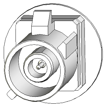
Connectors
The device is equipped with the following connectors:
- 1 x Main plug connector, code 1 (14-pin)
- 1 x RF antenna connector - FAKRA, code I (male)
(Type4003only)
Note
The connector performance is certified for this minimum number of mating cycles:
- Main plug connector: 10 cycles
- FAKRA (antenna) plug: 100 cycles
If the number of mating cycles exceeds these guidelines, plug characteristics (e.g. electrical contact resistance, IP protection) may lie outside those specified; meaning, the mating cycles can be carried out without quality problems at least for the minimum numbers of mating cycles.
The CANlink wireless system is not designed for a high number of mating cycles.
Ideally the device is configured with an adapter cable from the Launch Kit in the first instance and in the second step installed and cabled within the machine.
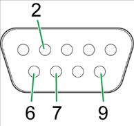
Main plug connector
Use the main plug connector to connect the device to the CAN bus and supply it with power.
For the pin assignment of the main plug connector, see the following overview.
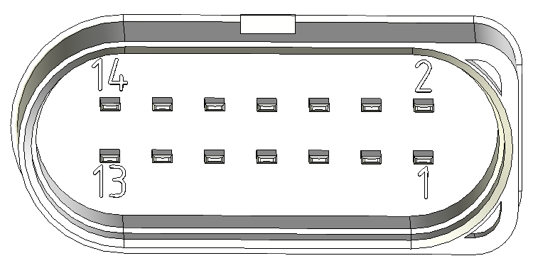
| Pin | Designation | Description |
|---|---|---|
| 1 | Terminal 30 / VCC | Power supply |
| 2 | Factory setting 1 | Input |
| 3 | Terminal 31 / ground | Power supply |
| 4 | Analog input 1 | I/O input |
| 5 | Analog input 2 | I/O input |
| 6 | Not used | - |
| 7 | Digital output | I/O output |
| 8 | Terminal 15 | Input (ignition signal) |
| 9 | Factory setting 2 | Input |
| 10 | Terminal 31 / ground | Power supply |
| 11 | CAN2-High | CAN, bidirectional |
| 12 | CAN2-Low | CAN, bidirectional |
| 13 | CAN1-High | CAN, bidirectional |
| 14 | CAN1-Low | CAN, bidirectional |
Note
Risk of property damage
Leakage and contamination due to an increased number of mating cycles and improper disconnecting of the main plug connector.
- Make sure the device is switched off during installation.
- Do not forcibly lever the main plug connector off the device connector.
- Refer to the handling manual from the manufacturer at Automotive Connectors/DeyTrade Connecting - Handling Manual FEP Sealed Connectors
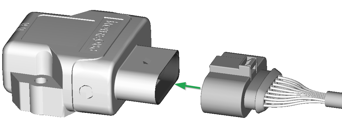
Connect main plug connector
Carefully connect the cable with the main plug connector. When connecting the plug, there must be a clear audible click.
Then the lock is correctly engaged.
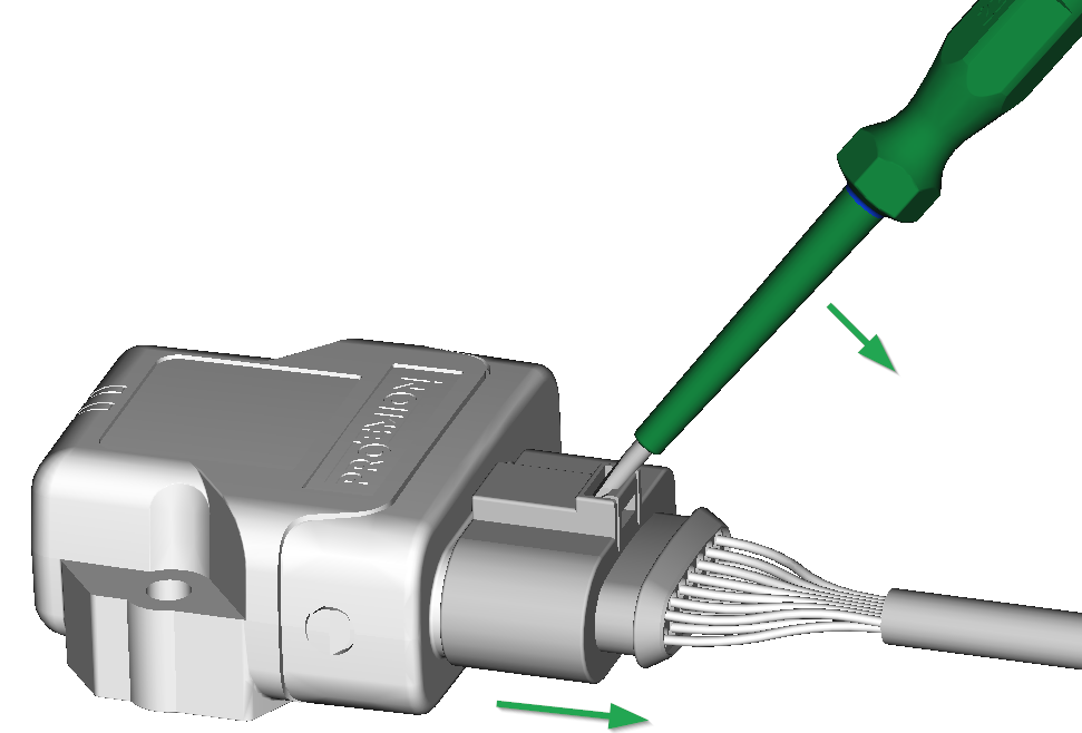
Disconnect main plug connector
Use an appropriate flat-blade screwdriver to release the lock. To do this, insert the screwdriver into the tab from above, then gently lever it down and back. At the same time, pull the plug slightly backwards by hand. If you can hear a click, the lock has been released and the connector can be removed.
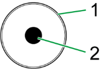
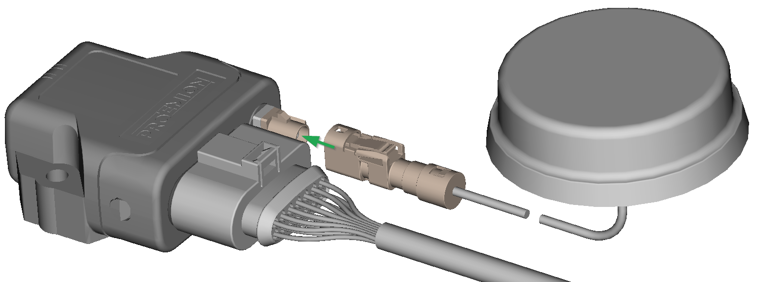
RF Antenna
Using the FAKRA antenna connector (on Type 4003), connect the device with an RF antenna to receive Wi-Fi® / Bluetooth signals.
| Pin | Designation | Description |
|---|---|---|
| Inner pin | Signal | Wi-Fi® or Bluetooth signal |
| Outer pin (shielding) | Ground | Shielding/ housing |
Note
With Type 4001, antenna connector is replaced by an integrated antenna.
Note
The wireless antenna port is designed for a minimum number of 100 mating cycles. If the minimum number of mating cycles is exceeded, individual parameters could be out of the specification; meaning, the mating cycles can be carried out without quality problems at least for the minimum numbers of mating cycles. The basic function of the antenna port remains intact.
Connect antenna connector
Ensure that the coding of the BT/Wi-Fi® Antenna is matching the coding of the antenna connector at the CANlink® wireless 4000.
Carefully connect the antenna with the FAKRA connector.
When connecting the plug, there must be a clear audible click. Then the lock is correctly engaged.
Disconnect antenna connector
Release the marked lock and carefully pull the plug backwards.

Cable Management
Note
Risk of property damage.
- Fasten the cable harness with a suitable strain relief near the main plug connector in order to avoid the transmission of any tension, strains or vibrations.
- Ensure that there is minimum bending radius of 8 times the outer diameter of the cable harness.
Protective Cover
Protect the connector and the cable with sufficient covers and cable tubing:
Warning
The following parts are not distributed by Proemion and can only be requested from the manufacturer with a minimum order quantity of 500 units, see Schlemmer.
The following part numbers from the supplier Schlemmer are recommended for the protective cover: 7807174, 7807207, 7807624:
Custom Cable for Main Plug
When creating a customized cable harness for the system integration of the CANlink® wireless 4000, some important recommendation for the setup of the main plug connector and cable must be considered.
It is recommended to use the connector components included in the Connector Kit, see Launch Kit to create a custom cable harness.
Note
Risk of property damage.
- This chapter contains some important advices. Please follow the instructions from the connector manufacturer and general rules for creating and protecting cable harnesses.
Note
Risk of property damage.
Water penetration due to capillary action of the cable strands.
- Ensure that both ends of the cable strands are sealed and assembled in the correct manner and in accordance to the manufacturer's specifications.
| Product | Recommendation |
|---|---|
 |
For the cable assembly it is essential that the instructions from the handling manual of the connector supplier are followed. Especially the main sealing, wire sealing and dummy plugs must be installed in the right manner. Refer to Automotive Connectors/DeyTrade Connecting - Handling Manual FEP Sealed Connectors. |
 |
Use only the recommended tooling for machine processing. Refer to Connector Kit Datasheet. It is recommended to use tinned contacts. This corresponds the material of the pins |
 |
Use the wire sealing which fits to the outer diameter of the used wires |
 |
Cover the unused contact sockets with dummy plugs to protect the connection from dust and humidity |
Safety Information
The following sections contain important information on how to avoid life-threatening situations and injuries and how to prevent product damage.
Safety Instructions
DANGER: Failure of safety-related functions due to deficient data transmission or incorrect connection to safety-relevant communication systems.
Risk of severe or fatal injury.
The device operates using radio signals and is not authorized for use in safety-related applications. Insufficient mobile and Wi-Fi® network availability, interference or malfunctions of the device can cause faulty data transmission. Because of this, data transmission cannot be guaranteed at all times and under all conditions.
The device is not designed, certified, or authorized for use in functional safety or safety-related applications (as defined in ISO 26262 or comparable standards).
Any failure, interference, misconfiguration or misuse — whether in wireless communication or wired interfaces (e.g. powertrain CAN, safety-relevant I/O, other functional-safety buses) — can lead to malfunction of safety-critical systems.
- Never operate this device in machines or applications where life depends on the fault-free operation of this device.
- Never use this device to transmit, modify, block, or otherwise influence safety-relevant communication (e.g. powertrain CAN or other functional safety networks).
- The system integrator is fully responsible for ensuring that the device is connected and configured only in ways that cannot interfere with safety functions.
- Never rely solely on wireless devices for essential communications.
- The device is designed to be used in systems which must be checked for conformity with the respective valid legal requirements prior to putting into operation. The system integrator of the device is responsible for ensuring that all local regulations and provisions are observed.
DANGER: Failure of communications systems in aircraft due to radio-frequency energy.
Risk of severe or fatal injury.
- Disconnect the power supply to the device before entering the aircraft.
- Make sure the device cannot be switched on inside the aircraft.
- Note the information in Power Management.
DANGER: Danger of explosion due to the operation of electrical equipment in potentially explosive atmospheres.
Risk of severe or fatal injury.
- Observe the applicable regulations and precautions for potentially explosive areas.
- Do not mount the antenna in the close proximity of easily ignited substances (e.g. fuel tanks) and insufficiently shielded electronic devices.
Danger of interference with medical equipment caused by radio frequency (RF) energy.
Risk of severe or fatal injury
Medical equipment may be sensitive to RF energy. The functioning of cardiac pacemakers, other implanted medical devices and hearing aids can be affected if the CANlink® wireless 4000 is located too close to the medical devices
- Observe the local regulations for use of mobile radio devices in hospitals or other medical facilities. Disconnect the power supply to the device when local regulations in sensitive areas require that you do so.
- If you use a cardiac pacemaker or other medical device, do not come within the close vicinity of the switched-on CANlink® wireless 4000 and its antenna
- If in doubt about potential danger, contact a physician or the manufacturer of the medical equipment to verify that it is properly shielded
Danger to life due to electric shock!
Risk of severe or fatal injury
- Never use the device if you suspect damage to the power supply unit or the device, or if there is visible damage to the power supply unit or the device.
Danger to life due to electric shock!
Risk of severe or fatal injury
- Never carry out repairs to the device yourself. Contact the Proemion support. The device does not contain any parts that can be repaired or maintained by the user.
Overload damage due to malfunction.
Risk of severe or fatal injury
- To limit power in the event of malfunction, secure the DC power supply circuit during installation with an external 1 A fuse.
Health hazards of radio-frequency energy.
Risk of minor injury
- During operation, observe a distance of at least 20 cm between the antennas and personnel.
Interference with electronic equipment caused by radio-frequency energy.
- Do not use the device with damaged cables or plugs. Cables and plugs must always be shielded.
- Observe all special regulations and disconnect the power supply to the CANlink® wireless 4000 if its use is prohibited or if you have doubts as to whether operation can cause interference or dangers.
Risk of property damage.
- The device must be installed, connected, and commissioned by a qualified technician.
- Disconnect all the connections to the device before starting to use it.
- Also disconnect any independently supplied output load circuits.
- Provide all the device connectors with plugs and any protection caps required to ensure protection class IP6K7.
- Only mount the device in the installation position shown in Mounting the Device.
- Never immerse the device in water or other liquids.
- The device must only be opened by the manufacturer.
- The device must only be repaired by the manufacturer.
- Do not operate the device without antennas.
- Pay attention that all the plug and cable connections can be made according to the correct assignment and without the need for any excessive force.
- Keep substances that contain solvents away from the type label.
Risk of property damage.
Damage to the device due to improper power application
The correct order of applying voltage to the device terminals CL15 and CL30 must be observed when powering on and powering off.
POWER ON
First power on CLAMP30, then CLAMP 15.
POWER OFF
The opposite order must be followed Power off CLAMP15, then CLAMP 30.
If this order is not maintained, the device can fail to boot.
Risk of property damage.
Damage to the device due to water penetration
- The device was tested against water jets according to IPxK6 of ISO 20653 standard.
Different loads, e.g. with a pressure washer or a higher flow rate, do not correspond to the intended use. - Never clean the CANlink wireless device with a pressure washer or similar.
Note
The horizontal distance between antennas can be calculated for every radio signal. The distance between two antennas must
- always be greater than 1/4 of the wavelength, and
- not a multiple of the wavelength.
If you use several antennas with different radio signals from each other, the distance of the antenna with the lowest frequency range must be observed.
Bluetooth / BLE
Frequency range 2.400 - 2.4835 GHz, wavelength 12.49 cm (1/4 = 3.12 cm)
Wi-Fi
- Frequency range 2.400 - 2.4835 GHz, wavelength 12.49 cm (1/4 = 3.12 cm)
- Frequency range 5.150 - 5.725 GHz, wavelength 5.17 cm (1/4 = 1.29 cm)
Example If you are using 2.4 GHz Wi-Fi®, the distance between the two antennas must be at least 3.2 cm.
Avoid the distances 19.23 cm, 12.49 cm and multiples of these values.
CE Notes European Union
The devices described in this device manual may only be used in mobile or stationary systems in which the distance between antennas and persons is at least 20 cm. Furthermore, antennas may only be operated in conjunction with other antennas or transmitters when the correct horizontal distance between them is observed.
Note
Loss of CE conformity is possible.
Only use antennas with a maximum antenna gain (including cable and connector loss) of 3.8dBi for Bluetooth and Wi-Fi 2.4GHz-Band and 5.5dBi for Wi-Fi 5GHz-Band.
Changes or modifications to this device not expressly approved by the manufacturer can void the user's authority to operate the device under CE rules.
Note
Loss of CE conformity is possible.
This device is restricted to indoor use only when operating Wi-Fi channels in the frequency range 5150 to 5350 MHz for the following countries

Note
Loss of CE conformity is possible.
The allowed maximum equivalent isotropically radiated power (EIRP) according to ETSI for Bluetooth is
- Bluetooth Classic max. 10 dBm at 2.402 - 2.480 GHz
- Bluetooth LE max. 10.46 dBm at 2.402 - 2.480 GHz
- Wi-Fi max. 18.89dBm at 2.412 - 2.472 GHz
- Wi-Fi max. 19.62dBm at 5.150 - 5.725 GHz
- Wi-Fi max. 13.88dBm at 5.725 - 5.785 GHz
Note
Changes or modifications to this device not expressly approved by the manufacturer can void the user's authority to operate the device under CE rules.
FCC Notes USA
The devices described in this device manual may only be used in mobile or stationary systems in which the distance between antennas and persons is at least 20 cm.
The antennas must further not be co-located or operated in conjunction with any other antennas or transmitters.
Note
This device has been tested and found to comply with the limits for a Class B digital device pursuant to part 15 of the FCC rules.
These limits are designed to provide adequate protection against harmful interference in a residential installation.
This device generates, uses, and can radiate radio frequency energy and, if not installed and used in accordance with the instructions,may cause interference to radio communications.
There is no guarantee that interference will not occur in a particular installation.
If this device does cause interference to radio or television reception, which can be determined by switching the device on and off, the user is advised to try to correct the interference by one or more of the following measures
- Realign the receiving antenna or put it in a different place.
- Increase the distance between the device and the receiver.
- Connect the device and the receiver to different supply circuits.
- Consult the dealer or an experienced radio/TV technician for help.
Note
Loss of FCC certification possible.
Only use antennas with a maximum antenna gain of 3.8dBi for Bluetooth and Wi-Fi® 2.4GHz-Band and
5.5dBi for Wi-Fi® 5GHz-Band.
Note
Changes or modifications to the device not expressly approved by the manufacturer can void the user's authority to operate the device under FCC rules.
ISED Notes Canada
English
This product meets the applicable Innovation, Science and Economic Development Canada technical specifications.
This Class B equipment complies with the applicable ISED RSSs Standards and CAN ICES-003. Operation is subject to the following two conditions
-
This device may not cause interference, and
-
This device must accept any interference, including interference that may cause undesired operation of the device.
Radiation Exposure Statement
This device complies with radiation exposure limits prescribed for an uncontrolled environment for fixed and mobile use condition. This equipment should be installed and operated with minimum distance of 20cm between the radiator and the body of the user or nearby persons.
Maximum Antenna Gain
The maximum antenna gain including cable and connector loss in a fixed or mobile exposure condition must not exceed 3.8dBi for Bluetooth and Wi-Fi 2.4GHz-Band and 5.5dBi for Wi-Fi 5GHz-Band.
Warning
Harmful interference
This device is restricted to indoor operation only in the band 5150-5250 MHz to reduce the potential for harmful interference to co-channel mobile satellite systems
However, original equipment manufacturer (OEM) devices, which are installed in vehicles by vehicles manufacturers, are permitted
The high-power radars are allocated as primary users (i.e., priority users) of the bands 5250-5350 MHz and 5650-5850 MHz and that these radars could cause interference and/or damage to this device|
This device is not capable of transmitting in the band 5600-5650 MHz in Canada
Note
Changes or modifications to this device not expressly approved by the manufacturer can void the user's authority to operate the device under ISED rules.
Français
Ce produit est conforme aux spécifications techniques applicables d'Innovation, Sciences et Développement Économique Canada.
Cet équipement de classe B est conforme aux normes ISDE RSS applicables et à la norme CAN ICES-003. Son fonctionnement est soumis aux deux conditions suivantes
-
Cet appareil ne doit pas provoquer d'interférences, et
-
Cet appareil doit accepter toute interférence, y compris les interférences qui peuvent provoquer un fonctionnement indésirable de l'appareil.
Déclaration d'exposition aux rayonnements
Cet appareil est conforme aux limites d'exposition aux rayonnements prescrites pour un environnement non contrôlé dans des conditions d'utilisation fixe et mobile. Cet équipement doit être installé et utilisé à une distance minimale de 20 cm entre le radiateur et le corps de l'utilisateur ou des personnes à proximité.
Gain d'antenne cellulaire maximal
Le gain d'antenne maximal, y compris les pertes du câble et du connecteur dans des conditions d'exposition fixe ou mobile, ne doit pas dépasser 3.8dBi pour Bluetooth et Wi-Fi 2.4GHz- bande de fréquence et 5.5dBi pour Wi-Fi 5GHz-bande de fréquence.
Warning
Interférences nuisibles
Cet appareil est limité à un fonctionnement en intérieur uniquement dans la bande 5150-5250 MHz pour réduire le potentiel d'interférences nuisibles aux systèmes mobiles par satellite sur le même canal. Toutefois, les dispositifs de fabricant d'équipement d'origine (OEM), qui sont installés dans les véhicules par leurs constructeurs, sont autorisés|
Les radars haute puissance sont considérés comme utilisateurs principaux (c'est-à-dire utilisateurs prioritaires) des bandes 5250-5350 MHz et 5650-5850 MHz et ces radars pourraient causer des interférences et/ou endommager cet appareil
Cet appareil n'est pas capable d'émettre dans la bande 5600-5650 MHz au Canada
Note
Les changements ou modifications de cet appareil non expressément approuvés par le fabricant peuvent annuler le droit de l'utilisateur à utiliser l'appareil selon la réglementation ISDE.
Warranty and Liability
Proemion assumes no liability for defects caused by normal wear, external influences and incorrect installation, operation or maintenance.
This also applies if the customer or a third party modifies the devices, any accessories, or the software without permission from Proemion.
Getting Started
The following sections describe the first steps that are required for the initial commissioning of the device.
Furthermore, it contains useful information on how to connect, configure, and mount the device.
Installing Software
Use the Proemion Configurator software to configure the device.
You can evaluate the transmitted data with:
- the Remote Service Tool software,
- a 3rd Party App for Android or iOS via Byte Command Protocol API,
- the RM CAN Device Monitor Pro CANopen.
Use the Firmware Programmer software for firmware updates.
The software can be downloaded from our Download Center.
| Software | Path on Download Center |
|---|---|
| Proemion Configurator | 03_Proemion Tools Software\01_Software\01_Proemion Configurator |
| Firmware Programmer | 03_Proemion Tools Software\01_Software\02_Proemion Firmware Programmer |
| Remote Service Tool software | 03_Proemion Tools Software\01_Software\04_Remote Service Tool |
| RM CAN Device Monitor Pro CANopen | 05_Utilities\01_RM CAN Device Monitor |
| USB driver | 05_Utilities\06_USB Drivers |
Execute the relevant application file (setup.exe, install.bat or similar) and follow the instructions on the screen to install the software on your PC.
RM CAN Device Monitor Pro CANopen
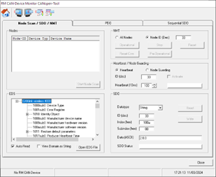
The RM CAN Device Monitor Pro CANopen can load an .eds file, and read and write to any address in that specification.
One disadvantage of this tool is that any operation can only be done in a serial fashion:
- Select object
- Edit settings
- Write object
- Repeat.....
This means that common tasks may be more quickly performed with a .dod file and the Proemion Configurator.
Proemion Configurator
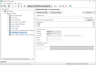
The Proemion Configurator is our default software for configuring the Proemion CLM and CLW device families.
With this tool, you can load in a set of Objects to read or program, and quickly setup the device.
This is our recommended method for setting up your CANlink® wireless 4000, and will form the basis for explaining how to configure the device in this document.
The Proemion Configurator can be downloaded from Download Center under: 03_Proemion Tools Software > 01_Software > 01_PROEMION Configurator
See Connect to Proemion Configurator for connection options.
Connecting the Device
For connecting the device with a PC, see the CANlink wireless 4000 User Guide.
Warning
Overload damage due to malfunction.
Risk of severe or fatal injury.
To limit power in the event of malfunction, secure the DC power supply circuit during installation with an external 1A fuse.
Note
Risk of property damage.
- The device must be installed, connected, and commissioned by a qualified technician.
- Ensure the power supply is disconnected before connecting the device.
- Only use components from the starter kit or the available accessories.
Refer to chapters Launch Kit and Software and Accessories.
If you have any questions or anything is unclear, please contact our support before getting started. See chapter Service and Support.
Connecting an external antenna
The Type 4003 features an FAKRA antenna connector for connection of the RF antenna Bluetooth/Wi-Fi® antenna (part number 157000126).
Tip
You can request more information about other permitted RF antennas using the Proemion support form at Support.
Danger
Danger of explosion due to the operation of electrical equipment in potentially explosive atmospheres.
Severe injury or death.
- Observe the applicable regulations and precautions for potentially explosive areas.
- Do not mount the antenna in the close proximity of easily ignited substances (e.g. fuel tanks) and insufficiently shielded electronic devices.
Warning
Health hazards of radio-frequency energy
Slight or medium injury.
- Make sure the device is switched off during installation.
Note
Property damage
The device or antenna can be damaged.
- Do not shorten or lengthen antenna cables.
Note
Reduced antenna gain
Problems with the wireless connectivity can be caused by an insufficient antenna setup.
- Only use the antennas which are supplied as Proemion accessories.
- Change the mounting position of the CANlink® wireless 4000 to reduce the distance between antenna and the device.
- Do not extend the antenna cable. Order an alternative antenna with longer antenna cable.
- Keep the length of the antenna cable as short as possible.
- In case of using the antennas which are supplied with the hardware kit or as Proemion accessories: Ensure that the minimum bending radius of the antenna cables is 8 times the outer diameter.
Note
Loss of FCC certification possible.
- Only use antennas which are approved for the frequency range used.
- Only use antennas which do not cancel the Wi-Fi® or the Bluetooth qualification.
- Keep the end of the antenna away from metal components to avoid detuning.
CAN
Connect the device interfaces to the CAN bus whose data you want to log or send. For test purposes, connect the device to a PC using a communication gateway (e.g. PCAN-USB - CAN/USB Interface).
The CAN connection terminal CAN-High and CAN-Low signals must match the signals of the connector on the device. You can connect Ground of the supply connector with CAN-GND because there is no galvanic isolation.
The following table provides an overview of the CAN bit rates in relation to the bus length:
| CAN baudrate | Maximum bus length |
|---|---|
| 1 Mbit/s | 25 m |
| 800 kbit/s | 50 m |
| 500 kbit/s | 100 m |
| 250 kbit/s | 250 m |
| 125 kbit/s | 500 m |
| 50 kbit/s | 1000 m |
CAN bus termination
In any bus system, signal reflections at the end of a wire or cable can cause interference which can in turn cause transmission errors. To minimize these reflections, place a terminator at each end of transmission lines.
The terminating resistance between CAN-High and CAN-Low must match the characteristic impedance of the transmission cables. In CAN bus networks, normally unshielded, twisted cable pairs are used for signal transmission.
The characteristic impedance of the transmission lines is roughly 120 Ohm.
The terminator between CAN-High and CAN-Low must be 120 Ohm.
Power supply
The device is supplied with power via the CAN connector.
Note
When switching on, terminal 30 must always be connected to the power supply before terminal 15 changes to status high.
Otherwise the device may not initialize correctly.
Note
For tests, firmware and configuration updates in the laboratory setup, the power supply and cables from the launch kit must be used.
See chapter Launch Kit.
Connect to Proemion Configurator
The Proemion Configurator is our proprietary software for configuring the Proemion CLM and CLW device families.
A connection is established via CAN to provide a fast and fault-resistant connection.
The software can be freely downloaded from the Proemion Download Center under: 03_Proemion Tools Software > 01_Software.
Connect over CAN bus
Independently of how the device is configured wirelessly, you can connect via CAN bus.
In order to connect to any device on the CAN bus, the device Node ID must be known, and the bus baud rate.
Tip
The default configuration after a Factory Reset has a CAN bitrate of 250 kbit/s, and a Node ID of 34.
PCAN-USB Connection
The Proemion Configurator supports the PCAN-USB dongle. This device plugs into a USB port, and interfaces directly with the CAN bus.
The PCAN-USB dongle is listed on our Software and Accessories page.
Once the PCAN drivers have been installed, and the dongle is connected to the bus, it must be set up in the Proemion Configurator settings.
-
Select Communication Settings.
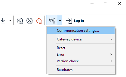
Figure 1: Communication Settings -
Select Peak PCAN-USB
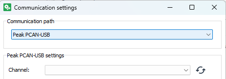
Figure 2: Peak PCAN-USB -
Scan for the correct PCAN dongle..
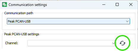
Figure 3: Scan for PCAN-USB -
..and select.
Ensure the selected baudrate is the same as the CAN bus.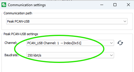
Figure 4: Select PCAN-USB -
Click 'OK', and the Connection Settings icon will turn green if the PCAN dongle is communicating with the Proemion Configurator.

Figure 5: Green connection
DOD files
The Proemion Configurator uses a .DOD file to read from, and write to the device for full configuration.
Sample .DOD files are provided for use, and can be found in the following location:
-
Enter
%AppData%into the Windows File Explorer address bar.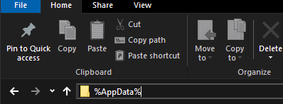
Figure 6: Automatic update -
This will be expanded to a directory under your user profile.
- From this directory, navigate down through the following directories:
- Proemion GmbH
- Configurator (or Proemion Configurator)
- Device-Application-Data
- Demos
- CANlink wireless 4000
- Here you will find several
.DODfiles to use, and form the basis of your intended device configuration.
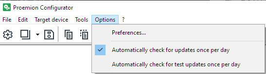
Note
All the files in this directory are automatically updated daily (when the Proemion Configurator is run).
If you modify a file in this directory and want to revert back to the default version, simply delete the file, and it will be re-downloaded.
When modifying these files, we recommend to save to some other directory, and keep these as a reference.
There are two main types of .DOD files in this directory:
- 'Default'
.DODs clw4001_Default.DODclw4003_Default.DOD- More specific
.DODs
The 'default' files are provided for both the 4001 (internal antenna) and 4003 (external antenna) models.
These provide all the objects typically required to configure the device. If needed, additional object can be added.
These files are valid for the latest firmware release.
The other more specific .DODs are much smaller, and offer only what is required to configure basic needs for a specific use: Configuring a device as a Bluetooth Server, for example.
The same configuration may be done with the 'default' .DODs - but the addition possibilities may be overwhelming to the new user.
Loading a DOD
A .DOD file may be double-clicked in Explorer, or opened through the Configurator File > Open menu option.
Reading and Writing Objects
The Proemion Configurator uses the .DOD to read and write the device CANopen Object Dictionary.
The same objects are available and documented in the .EDS distributed with the firmware in the Proemion Download Center.
Each item in the Object Dictionary list contains the Index and Sub-Index of the object that it represents.
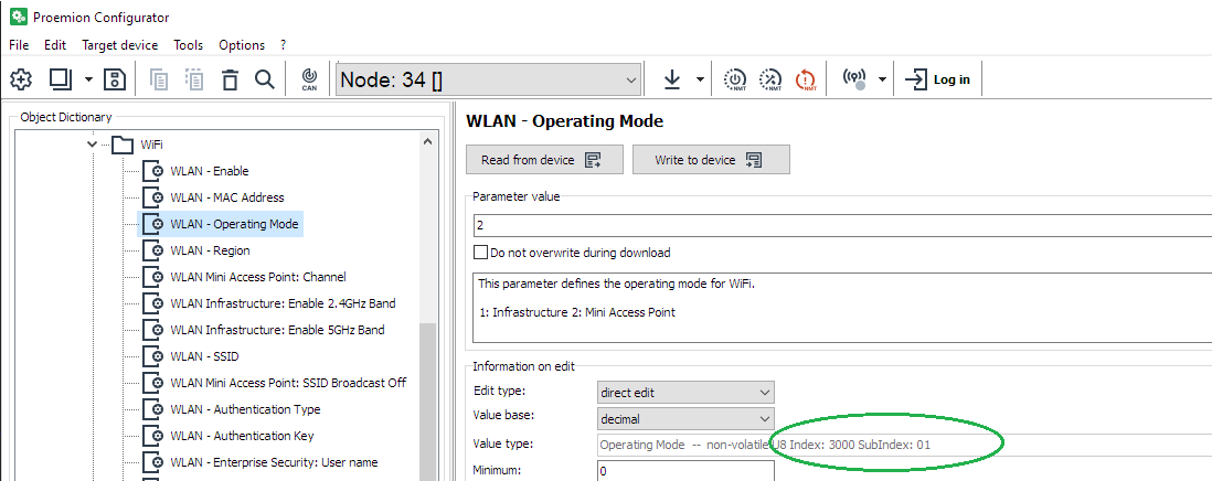
According to the read/write nature of that object, it can be interacted with in that way.
The 'Read from device' and 'Write to device' buttons are enabled according to the properties of the selected object.
Writing (setting properties)
There are several methods for writing individual or all entries.
Right-click on the object
Select one or more objects, and right-click.
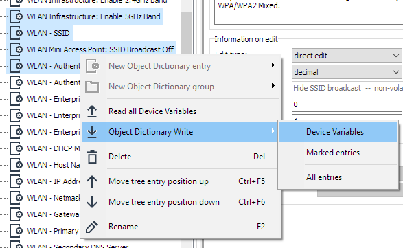
This brings up a context menu in which you can select to write:
-
Device Variables This writes all Device Variables to the device
-
Marked entries This writes the highlighted (selected) entries. In the example above, four entries would be written.
-
All entries This option writes all Device Variables, as well as any Custom CAN settings.
Write to device
Select an object to bring that into context, and click the 'Write to device' button to write only that object.
Target device Menu
The menu can also be used to write objects, in a similar way to a right-click.
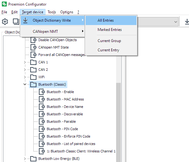
-
All Entries All Device Variables will be written.
-
Marked Entries This writes the highlighted (selected) entries.
-
Current Group In this image, all the objects in this 'folder'
-
Current Entry The current highlighted object(s)
Updating Proemion Configurator
The Proemion Configurator automatically downloads the latest configurations files necessary for configuring the {{ clw_4k }}, as well as updating the application itself.
Hardware installation
This chapter provides important notes regarding the hardware setup.
Note
Risk of property damage.
- Fasten the cable harness with a suitable strain relief near the CAN / power connector to avoid the transmission of any tension, strains, or vibrations.
- Ensure that there is minimum bending radius of 8 times the outer diameter of the cable harness
Note
Inadequate radio connection
The radio connection is affected by any obstacles and interference.
- Choose the mounting location so that as few obstructions as possible can influence the radio connection.
- When installing, observe the required minimum distance to other antennas and radio devices.
- Avoid interference with other wireless networks.
- Do not stick additional labels on the device.
Depending on the nature of the material, these stickers can severely impair the signal quality.
(Relevant for CANlink wireless 4001 with internal antenna). - The integrator must not modify the device (i.e. place RF-damping labels on it) or mount the device in such a way, that antenna performance is influenced.
- Implement a control-side end-to-end connection monitoring
It is the full responsibility of the integrator to integrate the device in their application in such a way that adequate antenna performance is achieved, and the regulatory requirements are fulfilled.
Note
Please be aware that the measured performance values from chapter Interfaces were determined in the free field without significant interference or signal dampening.
The maximum range, latency and the possible message throughput may vary considerably depending on the environmental influences, setup condition, the used antennas and, if applicable, the hardware installed for the Wi-Fi infrastructure.
Please consider these values just as approximate reference values which can be achieved in a specific test setup under ideal conditions.
It is the system integrators responsibility to verify the connection stability and performance under real ambient conditions as part of the final application and setup.
Mounting the Device
Below you will find instructions on how to mount the device.
To ensure the housing provides proper fire protection and to achieve the best possible reception of radio signals, make sure you install the device in the correct position.
Consider also the note regarding reduced antenna gain and other information in Connecting an external antenna.
Note
Risk of property damage.
- The device can be mounted with the plugs pointing to the left or right. Mounting with the plugs pointing up is not permitted. Mounting with the plugs pointing down is not recommended due to the risk of water ingress.
- Only mount the device in one of the installation orientations shown in this chapter.
- The device is protected against mechanical impacts according to class IK07 (IEC62262 impact energy 2 joules). To achieve a higher class, you must provide external protection when installing the device
Note
The mounting material is not included in the scope of delivery.
Optionally, you can use the MOUNTING SET M6 HOUSING GH0806 (part number 141000021).
The mounting set contains the following components:
- 2 flat headed screw ISO 14583 M6X30 TX
- 2 M6 self-locking hexagon nuts
Mounting
Below you will find instructions on how to mount the device.
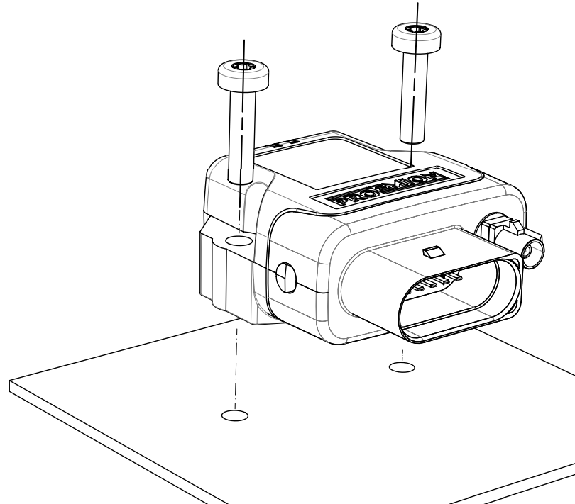
Directly affix the device with two flat-headed screw ISO 14583 M6X30 TX which are at least 30 mm long.
Tighten the bolts with a torque of 3.4 Nm ±10%.
To secure the bolts, we recommend using two hexagon nuts M6 self-locking.
Note
The mounting material is not included in the scope of supply.
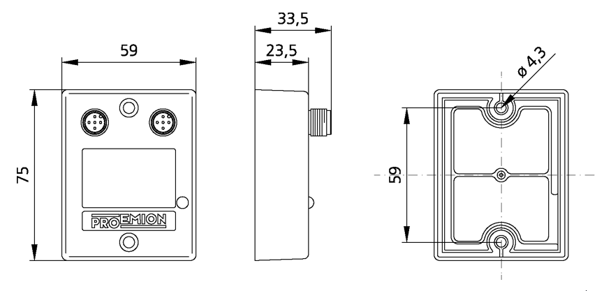
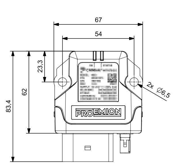
To get the distance of the mounting holes, please refer to chapter Technical Drawings.
Note
The Pressure compensation element at the bottom as shown in Device Elements must not be exposed to direct jet water.
Note
The recommended tightening torque for assembly is 3.4 Nm ±10%.
Note
The outer diameter of the head for the fixing screws must be smaller than 12.5 mm.
Note
For mounting environments that are exposed to the weather or other sources of water, Proemion highly recommends mounting the housing in a way that the gap between the housing and the mounting surface usually has a distance of ≥5 mm to prevent capillary action.
For more information, read the following recommendation.
To mount the device, proceed as follows:
Mount the device with 2 socket-head screws (M5) inserted in the mounting holes on the sides and screwed to the mounting surface (either directly if the device is not exposed to sources of water, or using a mounting plate, see recommendation above).
See Technical Drawings for detailed information on the distances between the holes.
Recommendation for devices exposed to sources of water:
Due to less space between housing and mounting plate, water can reside below the housing because of capillary action.
Especially, the area around the pressure-compensation element needs to be free of water.
Thus, the Mounting Orientation must ensure that no water is being held below this element.
If this cannot be achieved, you must add spacers below the mounting sockets or use a mounting plate that additionally supports the strain relief of the main connector cable.
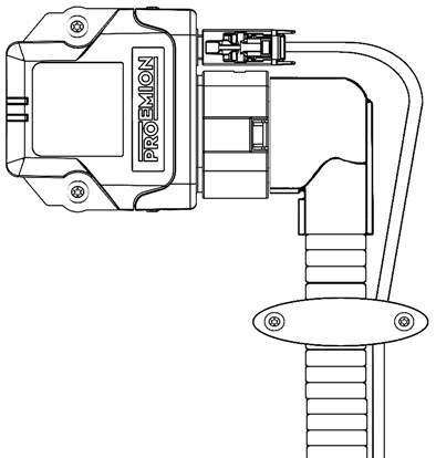
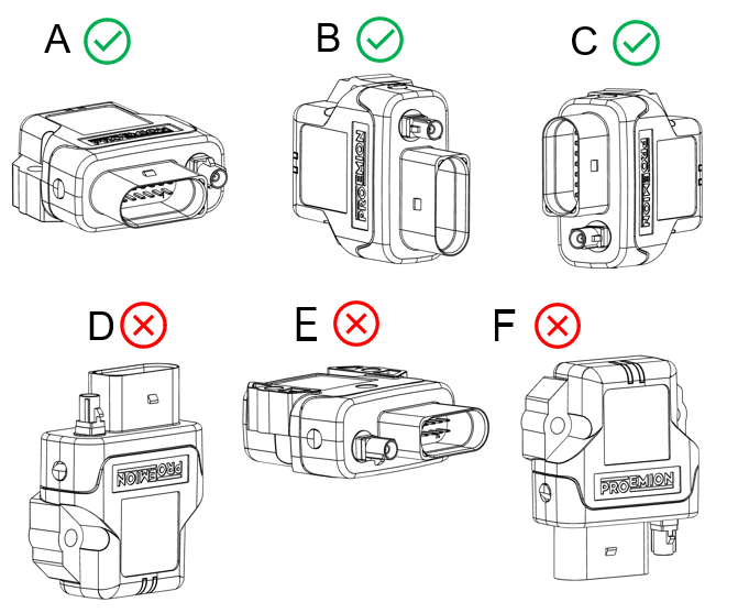
Mounting Orientation
The view elements of the two LEDs on the device do not comply with the flammability class required for a fire protection housing.
Note
Fire protection of the housing is only guaranteed in the installation positions shown in figures A, B or C or F.
Note
Please note that fire protection is not guaranteed in the installation positions shown in figures D and E.
Note
The mounting position F fulfills the requirements of a fire protection enclosure.
But is not recommended due to possible liquid ingress.
Note
To avoid water ingress, please make sure that the mounting orientation of your device is either as shown in figure A, B or C.
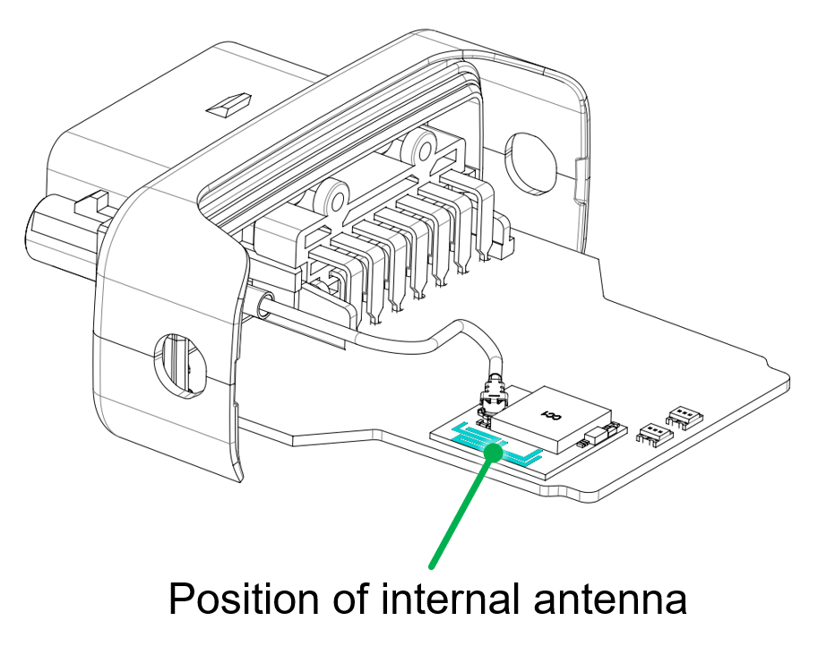
Internal Antenna
The internal antenna of the CANlink wireless variant 4001 is located on the top side of the PCB, therefore, it is recommended to mount the device in such a way that the top side also has the best possible alignment and free sight to its peer.
The 'top ' of the PCB is in the same orientation as the label.
So highest signal connection will be achieved with the two devices facing each other - label to label.
Please refer to figure Antenna positioning.
When using a setup with external antennas, it is also mandatory that the antennas have free sight to each other and are not blocked by any housing materials or other signal dampening materials.
Note
Reduced antenna gain
Problems with the radio connection can be caused by insufficient antenna alignment, interferences, and RF-damping labels.
- Do not stick RF-damping labels onto the housing of the device
External Antenna
Below you will find some important notes regarding the antenna setup.
Note
Inadequate radio connection
The radio connection is affected by any obstacles and interference.
- The antenna cable should be as short as possible to keep signal loss on the cable as low as possible.
- Do not extend the antenna cable. Only use the antennas which are supplied as accessories by Proemion. Bring the radio module closer to the antenna or order an alternative antenna with a longer antenna cable.
- An antenna, particularly outside, should be positioned as high as possible. This allows you to improve the range. This keeps the Fresnel zone clear - the higher, the better.
- Always protect connections on the outside cables, junctions, and antennas with protective tape.
- The external antenna is not to be used as lightning arrester. Select the position of the antenna carefully, use surge protector and do not route the antenna cable parallel to a lightning arrester.
- In the case of insufficient stability of the mounting, the quality of your antenna alignment can be reduced. When mounting the antenna, also think about wind and other outside influences such as ice and snow.
- Install the antenna in an open area, as far away as possible from any obstacles such as buildings, trees, other antennas, or metal objects.
- In case that there is a second antenna installed, calculate the minimum distance. The horizontal distance between antennas should be greater than 1/4 of its wavelength (absolute minimum separation), but it should not be located at the exact multiples of its wavelength (maybe avoid the first 3-4 multiples).
- Establish a sufficient ground connection to the pole, the device, the antenna and surge protection.
- In case of using the antenna supplied in the hardware kit, ensure that the minimum bending radius of the antenna cables is 8 times the outer diameter.
Migration from CANlink® wireless 3000
The CANlink® wireless 3000 was the predecessor of the CANlink® wireless 4000.
It offered many of the features of the CLW4000, but has been updated and improved in its successor.
CANlink® wireless 3000 and CANlink® wireless 4000 comparison:
| Feature | CLW3000 | CLW4000 |
|---|---|---|
| CAN buses | 1 | 2 |
| BLE interface | ❌ | ✔️ |
| Bluetooth PAN | ✔️ | ❌ |
| Bluetooth MultiPoint | ✔️ | ❌ |
| UDP/IP | ✔️ | ❌ |
| Wi-Fi AP needs password | ❌ | ✔️ |
| Simultaneous BT SPP and Wi-Fi connections | ✔️ | ❌ |
| wireless Configurator support | ✔️ | ❌ |
| Proemion Configurator support | ❌ | ✔️ |
| Protection Class | IP6k5 (3002) IP6K7 (3001) |
IP6K7 |
| Supply Voltage range | 8 - 32V | 6 - 36V |
Note
Changes between models
The CANlink® wireless 4000 is not a drop-in-replacement with respect to mounting and electrical connection, so the customer must adapt the existing installation according to their application.
There is a cable available 136200001 that allows the trivial electrical replacement of a CANlink® wireless 3000 by a CANlink® wireless 4000.
All accessories are listed in the Accessories chapter.
It is possible that some application configuration changes may be required.
Physical Differences
The CANlink® wireless 4000 housing has been upgraded to a superior IP class, and in order to contain the improved electronics. Therefore the mounting points and cabling has changed.
You can download the CAD files from our Download Center under: 01_Proemion_Devices > 08_CANlink wireless 4000 > 05_3D CAD Files
Housing
CANlink® wireless 3000 and CANlink® wireless 4000 dimensions:
| CANlink® wireless 3000 | CANlink® wireless 4000 |
|---|---|
 |
 |
Cabling
Since the CANlink® wireless 4000 supports two CAN buses, the cable has been upgraded.
Please check the CLW3000 information in the CANlink® wireless 3000 Device Manual Cable section.
The CANlink® wireless 4000 cable information is in the Cables section of this document.
Network Protocols
UDP
The CLW3000 supported UDP over IP, whereas the CANlink® wireless 4000 does not support this unreliable transport protocol.
The application can be easily modified to use TCP over IP.
The CANopen Object Dictionary objects 0x3010:0x16 and 0x3008:0x09 determine the network protocol in use.
The three options are:
-
Wi-Fi (TCP)
-
Bluetooth (SPP)
-
BLE
For information about setting the wireless interface, see Interface Configuration.
Bluetooth PAN connection
A Bluetooth Personal Area Network (PAN) is an ad-hoc wireless connection that allows the devices to communicate directly with each other.
The devices are tethered together over a Bluetooth Classic connection.
The CANlink® wireless 4000 does not support this legacy connection technology.
BLE is the recommended method of ad-hoc connections for low bandwidth applications (see BLE).
See Bluetooth, or Wi-Fi for higher bandwidth requirements.
Simultaneous interface protocols
In the CANlink® wireless 4000, only one protocol may be enabled at one time.
Single Wi-Fi band
In the CANlink® wireless 4000, it is recommended to only enable one Wi-Fi band at a time.
This only applies to the Client, as the Server determines the band.
If the Server is on channels 1 through 11, then that is the 2.4GHz band.
If the Server is on channels 36 through 48, then that is the 5GHz band.
To correctly configure a Wi-Fi Client device band, please observe the following table "Client Wi-Fi band".
| Band | Settings |
|---|---|
| 2.4GHz | Set 0x3000:0x10 [Enable 2.4GHz WiFi Band / Infrastructure only] to 1Set 0x3000:0x11 [Enable 5GHz WiFi Band / Infrastructure only] to 0 |
| 5GHz | Set 0x3000:0x10 [Enable 2.4GHz WiFi Band / Infrastructure only] to 0Set 0x3000:0x11 [Enable 5GHz WiFi Band / Infrastructure only] to 1 |
Object Dictionary
Due to the differences in the hardware and software of the CANlink® wireless 4000 compared to the CANlink® wireless 3000, the CANopen Object Dictionary (OD) has been modified as appropriate to work with the new device.
This has led to objects moving or changing values between the two ODs.
We have reduced the changes as much as possible, and summarize them here.
In order to reduce the amount of changes required for legacy applications using the CANlink® wireless 3000, we have implemented a software switch that reduces the footprint of the changes.
We call this 'Legacy Mode'.
Legacy Mode
This is an object in the OD that selectively enables and disables various features so that they more closely follow the schema employed in the CANlink® wireless 3000.
The Object Dictionary object 0x4000:0x30 [CLW3000 Legacy Mode BitField] is a 32bit bitfield.
Each bit represents one OD entry, and when set, configures that entry to more closely behave as it did in the CANlink® wireless 3000.
By default, these bits are all reset (disabled).
Tip
If changes to access objects in the CANlink® wireless 4000 Object Dictionary is prohibited, you can request additional fields to this object.
For more information, please fill out the support form at Support.
Entries
Bit0 - 0x0001
This enables legacy mode for object 0x3001:0x0B [Wireless connection state].
| Bit | Object affected | Behaviour Reset 0 |
Behaviour Set 1 |
|---|---|---|---|
0x0001 |
0x3001:0x0B |
0: Connection not established 1: Connection active |
1: Initialization 2: Status Ready 4: Connected 255: Error |
Example: Wireless Connection State
Using bit0 of the 0x4000:0x30 [CLW3000 Legacy Mode BitField] object:
When that object is set to 0x0001, when a wireless connection has been made, the value available at 0x3001:0x0B [Wireless connection state] will be 4, instead of 1 if that bit was not set.
This is the same value that was read after a successful connection in the CANlink® wireless 3000.
Firmware update
The firmware for the CANlink wireless 4000 series exists in two formats:
-
The application firmware only.
-
The application firmware and additionally the firmware for the radio module when available.
The second option is referred to as a "bundle", and supports new and improved functionality from the radio module.
Both options are explained in this section.
Certain previous versions of firmware require a certain installation sequence.
Refer to the corresponding release notes which can be found in the firmware directory.
The firmware files are available in the Download Center under: 01_Proemion_Devices > 08_CANlink wireless 4000 > 03_Firmware > CANlink wireless 4000 Firmware
| Firmware | Path in Download Center |
|---|---|
| Application | CANlink_wireless_4001.signed.binCANlink_wireless_4003.signed.bin |
| Bundle | \Bundle\CANlink_wireless_4001_bundle.signed.bin\Bundle\CANlink_wireless_4003_bundle.signed.bin |
Note
Either the device firmware or the 'bundle' may be updated with the Proemion Firmware Programmer.
The bundle may always be safely installed (but the update takes longer because it includes both binaries).
To save time, if the radio module version is unchanged (which is typically true), the device firmware only may be updated.
It will be clearly indicated if the bundle version must be updated in the firmware Release Notes.
More details can be found in the document Upgrading Firmware in the Firmware folder in the Download Center.
| Firmware | Path on Download Center |
|---|---|
| Application | 01_Proemion_Devices\08_CANlink wireless 4000\03_Firmware\ |
| Bundle | 01_Proemion_Devices\08_CANlink wireless 4000\03_Firmware\Bundle\ |
Prerequisites
To perform a firmware update, you need the Proemion Firmware Programmer software and a CAN connection with the device via a PCAN-USB CAN/USB interface.
The software can be downloaded from Download Center under: 03_Proemion Tools Software > 01_Software.
If you have an older CANview USB CAN/USB interface, follow the instructions for this device.
-
Install the Proemion Firmware Programmer prior to the update procedure.
-
Connect your PC to the CAN interface of the CANlink® wireless 4000 with a PCAN-USB CAN/USB Interface (including a 120 Ohm CAN bus termination resistor):
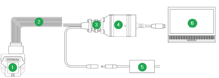
Figure 1: CANlink® wireless 4000 Connection to PC via PCAN-USB - CAN/USB Interface
| # | Item |
|---|---|
| 1 | CANlink® wireless 4000 |
| 2 | CLW4K Starter Cable |
| 3 | CAN bus terminator D-Sub/D-Sub, 120Ω |
| 4 | PCAN-USB - CAN/USB Interface |
| 5 | Power supply unit |
| 6 | PC with Proemion Firmware Programmer |
Select the firmware file
-
In the Proemion Firmware Programmer, click File > Open.
-
Select the
*.binfile with the correct firmware. This could be named something likeCANlink_wireless_4001.signed.binfor the device firmware update, orCANlink_wireless_4001_bundle.signed.binfor the bundle update.
The bundle update packages are in the \bundles\ subdirectory.
Configure the communication device
-
Open the Proemion Firmware Programmer.
-
In the main window of the Proemion Firmware Programmer, click the
 > COMMUNICATION SETTINGS in the drop-down.
The Communication Settings window opens: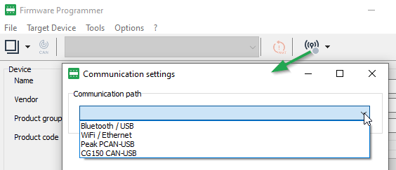
Figure 2: Communication Settings path -
Choose the Communication Path, i.e. the communication device, in this case "Peak PCAN-USB":
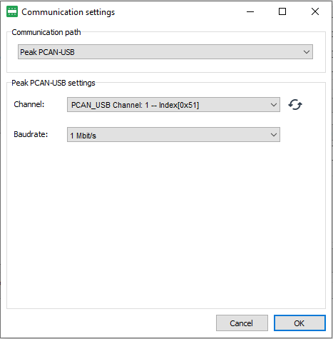
Figure 3: Communication Settings - PCAN -
Select the Channel and Baudrate. The default CAN baud rate is 250 kbit/s.
-
Click OK to save the settings.
The main window is shown again.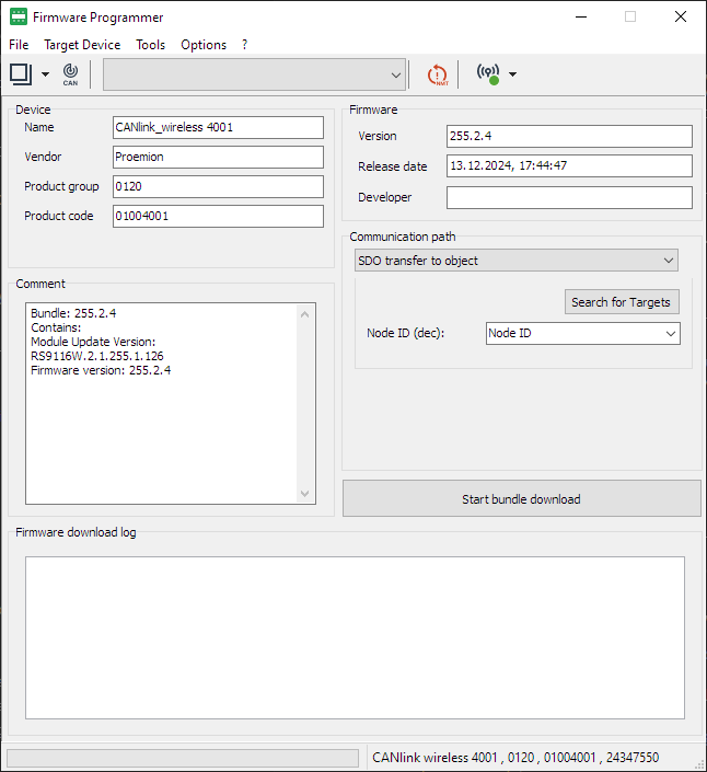
Figure 4: Firmware Programmer - main window
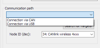
Select Communication Path
If a Bundle file was selected, the communication path is automatically set to SDO transfer to object.
If a device firmware file (CANlink_wireless_400x.signed.bin) was selected, the Communication path offers two options:
-
Connection via CAN
-
Connection via USB
Select the first option, via CAN.
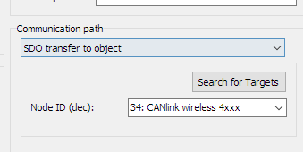
Select the device for the firmware update
-
In the main window of the Proemion Firmware Programmer, ensure that Connection via CAN is preselected in the Communication path field.
-
To start the Node scan, click Search for Targets.
A list of Node IDs found will be shown, and the first node automatically selected.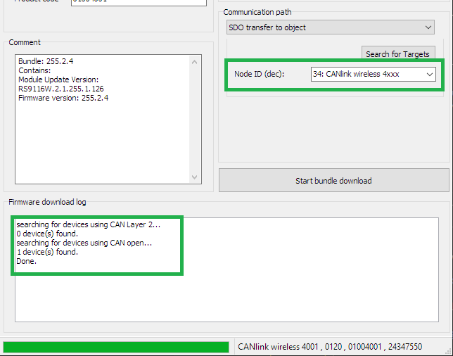
Figure 7: Firmware Programmer - Search for Targets -
Select the corresponding device (if necessary).
The default Node ID of the CAN 1 interface is 34 (decimal) and the found device is displayed as 34: CANlink wireless 4xxx. -
Click the Start firmware download button.
Device Firmware Update
During a the firmware update with only the Device firmware, both LEDs on the device rapidly flash green.
| CAN1 Baudrate | Update duration (approximate) |
|---|---|
| 250kb/s (default) |
02m00s |
| 1Mb/s | 01m30s |
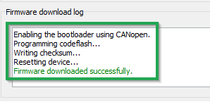
The following messages will appear in the Firmware download log:
Enabling the bootloader using CANopen.
Programming codeflash...
Writing checksum...
Resetting device...
The message Firmware downloaded successfully appears when the firmware update is complete.
Firmware Bundle Update
The firmware of the CANlink® wireless 4000 can be simply updated in one step using a Firmware Bundle. These files are called
-
CANlink_wireless_4001_bundle.signed.bin for the 4001 model
-
CANlink_wireless_4003_bundle.signed.bin for the 4003 model
These are located in the \bundles\ directory of the firmware package downloaded from the Download Center.
The bundle may only be updated using the CAN1 bus.
Update Process
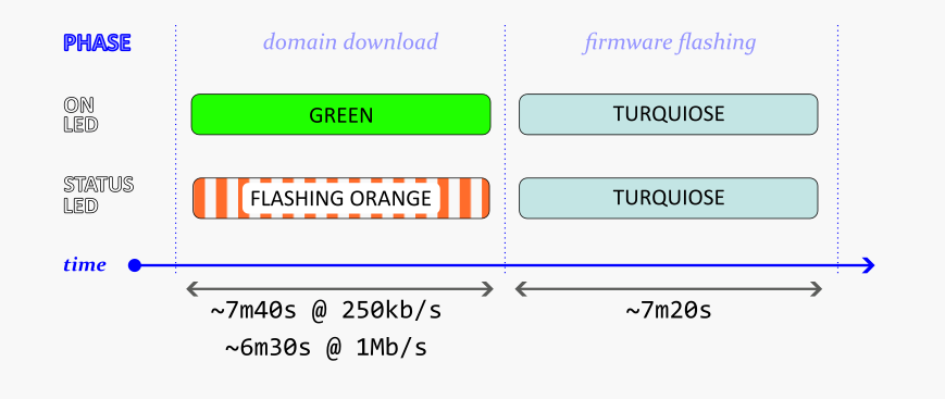
Update Timing
The Bundle Update process consists of two phases:
-
Download
-
Flashing
The duration of the Download phase depends on the configured device baudrate, whereas the Flashing phase remains a constant length.
| CAN1 Baudrate | Download duration (approximate) |
|---|---|
| 250kb/s (default) |
07m40s |
| 1Mb/s | 06m30s |
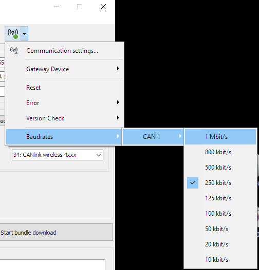
Both baudrate of the device CAN bus and the CANUSB dongle must be set to the same rate.
-
To set the baudrate of the device, see the CAN baudrate section under ObjectDictionary
-
To change baudrates in the Firmware Programmer, select the appropriate value in the Communication Settings
After a firmware update
The behavior of the firmware may have changed in the new version.
Please read the release notes included with the new version, to see if there has been any affect on your configuration.
The default values of some settings may have changed to comply with updated firmware: Please do a Factory Reset to set all values back to default.
Then you may configure your device accordingly.
Note
The firmware update may reset or add configuration settings of the device.
After the firmware update, reload your configuration to the device with the latest version of the Proemion Configurator software.
Functionality and Features
The following sections contain information on device functionality and features.
It provides details of the operating modes, interfaces, connectors, cables, pin assignments, and indicator elements.
Functions
The type 4001 (internal antenna) and 4003 (external antenna) support the following functions:
BLUETOOTH
- CAN-Bluetooth Interface
- CAN-CAN-Bluetooth Bridge
Wi-Fi
- CAN-Wi-Fi Interface
- CAN-CAN-Wi-Fi Bridge
BLE
- CAN-BLE Interface
- CAN-CAN-BLE Bridge
Use cases
Use Cases Overview
The CANlink® wireless 4000 is a CAN-to-wireless gateway.
The following table shows some possible applications with the device.
Point to point connections
A Point to Point connection transmits CAN data between only one device and another.

| Interface | Application | Remarks | Client Software |
|---|---|---|---|
| Bluetooth Classic | CAN - Mobile Device / PC Interface | - | Remote Service Tool, or a 3rd Party App for Android or iOS via Byte Command Protocol API. |
| CAN - CAN Bridge | Two CANlink® wireless 4000 devices communicating with each other. | n.a. | |
| Wi-Fi | CAN - Mobile Device / PC Interface | Wi-Fi Access Point mode. | Remote Service Tool, or a 3rd Party App for Android or iOS via Byte Command Protocol API. |
| CAN - Mobile Device / PC Interface | Wi-Fi Infrastructure mode. (Wi-Fi Infrastructure Mode requires an external Access Point) |
Remote Service Tool, or 3rd Party App for Android or iOS via Byte Command Protocol API. | |
| CAN - CAN Bridge | Two CANlink® wireless 4000 devices communicating with each other. Recommended communication technology for CAN-CAN bridge. |
n.a. | |
| BLE | CAN - Mobile Device / PC Interface | BLE 'Peripheral' role. | 3rd Party App for Android or iOS via Byte Command Protocol API. |
| CAN - CAN Bridge | BLE is not recommended for high-bandwidth application. See BLE Performance |
n.a. |
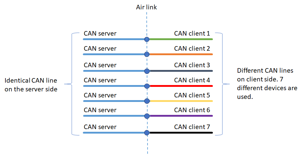
MultiPoint connections
Tip
When considering this diagram, remember that data from both CAN buses connected to the CANlink® wireless 4000 source device are sent wirelessly and put on the bus(es) of the destination device.

This configuration is where one CANlink® wireless 4000 is connected to, and shares CAN data with more than one other peer.
Each Client device receives all data present on the CAN bus of the Server, and puts it on their local CAN bus.
Each message on each of the Client's CAN bus is transferred to the Server.
A maximum of eight devices can be connected together: One Server with up to seven connected Clients.
Note
While each Client receives all CAN data present on the Server CAN bus, it will not receive data from other Client's CAN bus.
This is what MultiTalk is designed for.
MultiPoint is only available on the Wi-Fi interface.
See the MultiPoint documentation for instructions how to configure MultiPoint.
MultiTalk connections
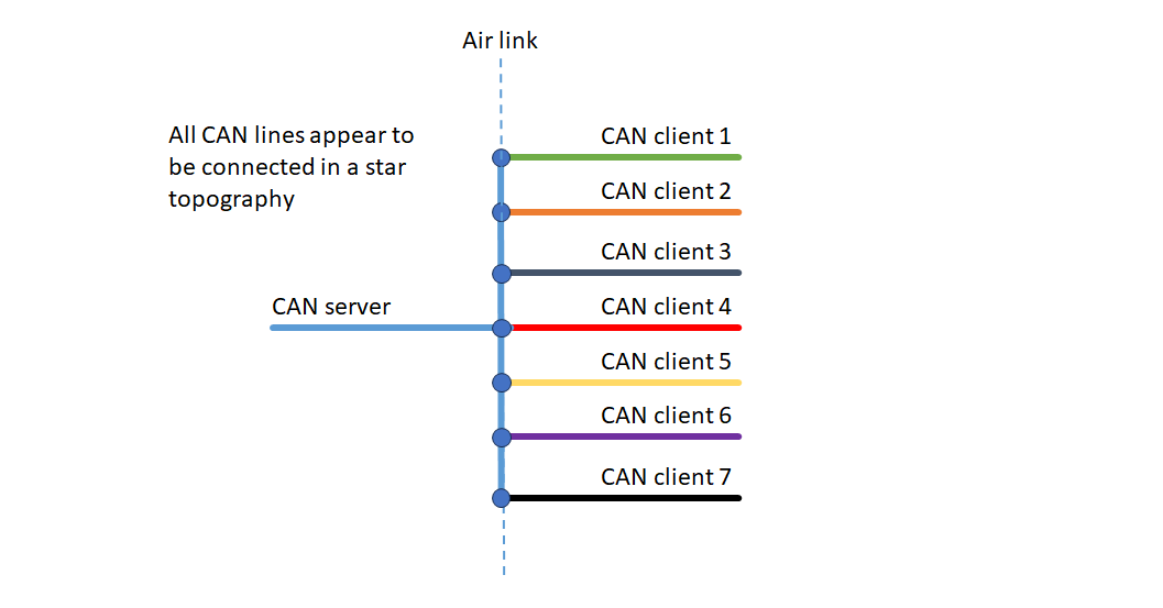
This is an extension of the MultiPoint configuration, where every device receives all CAN messages from every wirelessly connected device in the network.
The Server can be considered a Hub, distributing all messages to all peers.
For configuration, see MultiTalk configuration.
MultiTalk is only available on the Wi-Fi interface.
For an example of MultiTalk, see CTO Demonstration 1.
Wi-Fi Interface
The CANlink® wireless 4000 offers a Wi-Fi interface, typically used in one of two modes:
-
CAN-Wi-Fi Interface
CAN data is transmitted wirelessly to other Wi-Fi-capable devices such as PCs, smartphones, or tablets.
Sometimes referred to as 'Gateway' mode in this document. -
CAN-CAN-Wi-Fi Bridge
CAN data is transmitted wirelessly between two CANlink® wireless 4000 devices via a Wi-Fi connection.
The CAN-CAN-Wi-Fi Bridge acts as a substitute for CAN cables, e.g. in drag chains or remote control units.
Sometimes referred to as 'Bridge' mode in this document
Tip
Only one Wi-Fi band should be enabled at one time on the Client:
- CANopen object
0x3000:0x10enables 2.4GHz - Object
0x3000:0x11enables 5GHz
The band not used should be disabled.
CAN-Wi-Fi Interface
In operation as a CAN-Wi-Fi Interface, CAN data is transmitted wirelessly to other Wi-Fi-capable devices such as PCs, smartphones or tablets.
The CAN-Wi-Fi Interface features two operating modes: infrastructure mode and access point mode:
- In infrastructure mode, data transmission takes place via one or more access points.
- In access point mode, the CANlink® wireless 4000 additionally provides a Wi-Fi access point function.
Client and Server configurations
The CANlink® wireless 4000 can be configured to act in one of two roles over a Wi-Fi interface:
- Server - which waits for incoming connection requests from one or more..
- Client(s) - which attempts connection to a Server.
The Client is configured with the IP Address and appropriate port of the Server to connect to.
Tip
A device may either be configured as a Server, or a Client - not both.
- A Server may accept up to seven connections from different Clients, and is discussed further in the MultiPoint.
- A Client may only connect to one Server.
Encryption
The CANlink® wireless 4000 supports different Wi-Fi encryption schemes.
| Name | Authentication | Data Protection | Client Supported | Server Supported |
|---|---|---|---|---|
| None (OSA) | No | No | ✅ | 🚫 |
| WPA/WPA2 Mixed | Yes (shared password) | Data is encrypted | ✅ | ✅ |
To configure the encryption level, set the value of the CANopen object 0x3000:0x04 [WiFi Authentication Type] according to the requirements:
0: None (default)7: WPA/WPA2 Mixed
Warning
Firmware version ≥ 3.0
Using Open Authentication when device is configured as an Access Point is not supported in version ≥ 3.0.
Access Point authentication must be configured as 'WPA/WPA2 Mixed'.
The Access Point will not operate if 'WPA/WPA2 Mixed' is not configured, and a password specified in 0x3000:0x05 [WiFi Authentication Key].
(See Access Point Wi-Fi Password for more information).
Open Authentication is only available when configured in Infrastructure Mode (as a Client).
CAN-CAN-Wi-Fi Bridge
A Wi-Fi Bridge is how we refer to two CANlink® wireless 4000 devices connected directly to each other over a Wi-Fi connection.
One is configured as a Server, and the other, the Client.
The Server device can be configured in one of two ways:
- as a Wi-Fi Access Point (AP), or
- as a Wi-Fi Client connecting to an existing Wi-Fi Access Point.
In the first mode acting as an AP, 0x3000:0x09 [WiFi DHCP Mode] must be enabled.
In the second mode, an external Router must be used as the Access Point to which both devices connect.
CONFIGURING A BRIDGE
To start with a known 'clean' configuration, a factory reset can be initiated by writing 0x64616F6C to CANopen SDO object 0x1011:0x01.
See Factory Reset for details.
WiFi Server
Tip
This process can be simplified by using the configuration file clw400x_SetupWiFiServer.DOD to be found in the demo folder of the Proemion Configurator.
-
Set Access Point Mode
Set0x3000:0x01 [Operating Mode]to0x02 [Mini Access Point]. -
Set SSID
Set name of network as appropriate0x3000:0x02 [SSID]to "CLW4000Server". -
Set Authentication
0x3000:0x04 [Authentication Type]to0x07 [WPA/WPA2 Mixed]. -
Set appropriate password
0x3000:0x05 [WiFi Authentication Key]as appropriate.
(Wi-Fi Password for more information).
ChocolateCake4Breakfast!, for example. -
Set DHCP
0x3000:0x09 [DHCP Mode]to0x02 [Server]. -
Set WiFi region as appropriate
0x3000:0x25 [Wifi Region]. -
Select RF channel
Select an appropriate channel from the options in0x3000:0x0F [WLAN - Access Point Channel].
We recommend 5GHz band (channels from 36 to 165) unless necessary. -
Set IP Address as appropriate
0x3000:0x0A [IP Address]to192.168.0.34. -
Disable other interfaces
Disable Bluetooth by setting0x3008:0x03 [Bluetooth Enable]to0x00.
Disable BLE by setting0x3008:0x09 [BLE Enable]to0x00. -
Enable WiFi
Set0x3008:0x02to0x01 -
Enable WiFi server
Set0x3010:0x15 [EEP Connection Direction Configuration/Server or Client 1]to0x02 [Server enabled] -
Set connection type
Set0x3010:0x16 [EEP Connect Type 1]to0x01 [Socket] -
Set CAN Node IDs as appropriate
0x4050:0x03 [Node Id CAN1]to decimal34.
0x4050:0x04 [Node Id CAN2]to decimal35. -
Reboot device
WiFi Client
Tip
This process can be simplified by using the file clw400x_SetupWiFiClient.DOD configuration to be found in the demo folder of the Proemion Configurator.
- Set Infrastructure Mode
Set0x3000:0x01 [Operating Mode]to0x01 [Infrastructure]. - Set SSID
Set Server name of network as appropriate0x3000:0x02 [SSID]to "CANlink® wireless 4000Server". - Set Authentication
0x3000:0x04 [Authentication Type]to0x07 [WPA/WPA2 Mixed]. - Set appropriate password
0x3000:0x05 [WiFi Authentication Key]to the appropriate Server password. - Set DHCP
0x3000:0x09 [DHCP Mode]to0x01 [DHCP Client (WLAN infrastructure only)]. -
Set WiFi region as appropriate
0x3000:0x25 [Wifi Region]. -
Select RF band as appropriate
If the Server is on channels 1 through 11 (2.4GHz).
a. Set
0x3000:0x10 [Enable 2.4GHz WiFi Band / Infrastructure only]to0x01.
b. Set0x3000:0x11 [Enable 5GHz WiFi Band / Infrastructure only]to0x00.If the Server is on channels 36 through 165 (5GHz)
c. Set
0x3000:0x10 [Enable 2.4GHz WiFi Band / Infrastructure only]to0x00.
d. Set0x3000:0x11 [Enable 5GHz WiFi Band / Infrastructure only]to0x01. -
Disable other interfaces
Disable Bluetooth by setting0x3008:0x03 [Bluetooth Enable]to0x00.
Disable BLE by setting0x3008:0x09 [BLE Enable]to0x00. - Enable WiFi
Set0x3008:0x02 [Wlan Enable]to0x01 [Enabled] - Configure Connection Direction
Set0x3010:0x15 [EEP Connection Direction Configuration/Server or Client 1]to0x03 [Client enabled]. - Set connection type
Set
0x3010:0x16 [EEP Connect Type 1]to0x01 [Socket]. - Set Server Address
Set
0x3010:0x17 [EEP URL Address/Wlan Client only 1]to content of object0x3000:0x0A [IP Address]in Server device. -
Set CAN Node IDs as appropriate
0x4050:0x03 [Node Id CAN1]to decimal44.
0x4050:0x04 [Node Id CAN2]to decimal45. -
Reboot device
CAN-CAN Wi-Fi CANlink® mobile 3600 CANlink® wireless 4000 Bridge
A CAN-CAN bridge can be configured between a CANlink® mobile 3600 and CANlink® wireless 4000 over either a Wi-Fi or Bluetooth connection.
The Wi-Fi connection is recommended, and is documented here.
In this example, we configure the CANlink® mobile 3600 as:
-
Wi-Fi Access Point (AP)
-
Server
- Channel 36, 5GHz band
- WPA2 enabled
- Password:
ChocolateOnly4Breakfast! - CAN Node ID:
39 - IP Address and Port
192.168.0.39:30000
And the CANlink® wireless 4000 as:
-
Wi-Fi Client
-
CAN Node ID:
44
Server (CANlink® mobile 3600)
All objects in the following table are mandatory to set for the wireless module to function as a Wi-Fi Access Point.
| Object | Object Name | Value | Notes |
|---|---|---|---|
0x3008:0x03 |
Bluetooth Enable | 0 |
Disabled |
0x3008:0x09 |
BLE Enable | 0 |
Disabled |
0x3008:0x02 |
WiFi Enable | 1 |
Enabled |
0x3000:0x0F |
WLAN - Access Point Channel | 36 |
Channel 36 in 5GHz band |
0x3000:0x01 |
WLAN - Operating Mode | 2 |
Mini Access Point |
0x3000:0x09 |
WLAN - DHCP Mode | 2 |
DHCP Server |
0x3000:0x02 |
WLAN - SSID | CLM3600 |
Name of Network SSID |
0x3000:0x04 |
WLAN - Authentication Type | 7 |
WPA2 |
0x3000:0x05 |
WLAN - Authentication Key | ChocolateOnly4Breakfast! |
Network Key |
0x3003:0x01 |
WLAN - Socket Server Enable | 1 |
Enabled |
0x3000:0x0A |
WLAN - Static IP Address | 192.168.0.39 |
Address of Server |
0x3000:0x0B |
WLAN - Static Network Mask | 255.255.255.0 |
Network Mask |
0x3000:0x0C |
WLAN - Static Gateway Address | 192.168.0.1 |
Gateway Address |
0x3000:0x0D |
WLAN - Static Primary DNS Server | 192.168.0.1 |
Address of Server |
0x3000:0x0D |
WLAN - Static Secondary DNS Server | 192.168.0.1 |
Address of Server |
0x3003:0x02 |
WLAN - Socket Listen Port Number | 30000 |
Port Number |
0x3003:0x03 |
WLAN - Socket Listen Protocol | 0 |
TCP |
- Add other settings such as
0x4050:0x03 [CAN 1: Device CANopen Node ID]according to requirements. (In this example,39). - Reboot device
Client (CANlink® wireless 4000)
| Object | Object Name | Value | Notes |
|---|---|---|---|
0x3008:0x03 |
Bluetooth Enable | 0 |
Disabled |
0x3008:0x09 |
BLE Enable | 0 |
Disabled |
0x3008:0x02 |
WiFi Enable | 1 |
Enabled |
0x3000:0x01 |
WiFi Operating Mode | 1 |
Infrastructure |
0x3000:0x09 |
WiFi DHCP Mode | 1 |
DHCP Client |
0x3000:0x04 |
WLAN Authentication Type | 7 |
WPA/WPA2 Mixed |
0x3000:0x02 |
WLAN SSID | CLM3600 |
Name of Network SSID |
0x3000:0x05 |
WLAN - Authentication Key | ChocolateOnly4Breakfast! |
Network Key |
0x3010:0x17 |
URL Address/WiFi Client only 1 | 192.168.0.39 |
Server IP Address |
0x3003:0x02 |
Socket Listen Port/WiFi only 1 | 30000 |
Server Port Number |
0x3000:0x10 |
Enable 2.4GHz WiFi Band / Infrastructure only | 0 |
Disabled |
0x3000:0x11 |
Enable 5GHz WiFi Band / Infrastructure only | 1 |
Enabled |
0x3010:0x15 |
EEP Connection Direction Configuration/Server or Client 1 | 3 |
Client Enabled |
0x3010:0x16 |
EEP Connect Type 1 | 1 |
TCP Socket |
- Add other settings such as
0x4050:0x03 [CAN 1: Device CANopen Node ID]according to requirements. (In this example,44). - Reboot device
Wi-Fi Password
Access Point
When configured as a Wi-Fi Access Point (AP), the CANlink® wireless 4000 allows connections from one or more Wi-Fi Clients.
(More than one connection to a Client requires Multipoint/MultiTalk).
In order to prevent an insecure network, the AP must be configured:
- with WPA2 enabled, and
- with a 'complex' password
The password requirements mandate all of the following:
- length between 24 and 63 characters
- at least 1 lower case
- at least 1 upper case
- at least 1 numerical (0 - 9)
- 1 special character (
!#&, etc)
Tip
If the AP does not accept Client connections, check 0x3001:0x0C [Error Code/ WiFi - Bluetooth].
- If the password is not valid when creating the AP, the error code
0xDEADC0D1will be present. - If the AP was started with Open Authentication selected, the error code
0xDEADC0DEwill be present.
Client Configuration
When configured as a Client, any form of connection may be made:
0: Open authentication (None)7: WPA/WPA2 Mixed with whatever password is configured on the Server.
Hidden Wi-Fi SSID
The CANlink® wireless 4000, if defined as a Wi-Fi® Access Point (AP), can disable the broadcast of the network SSID.
Clients can still connect to this AP, but they must know the SSID beforehand.
Also, when configured as a Client device, it is possible to connect to an AP with a hidden SSID (if that SSID is known).
Server Configuration
The device must be initially configured as a Wi-Fi® Server.
-
Set
0x3000:0x1F [WiFi Hide SSID broadcast]to1 (Enabled). -
Hidden SSID is only possible within a secure network, therefore, set
0x3000:0x04 [WiFi Authentication Type]to7 [WPA/WPA2 Mixed]to enable it. -
Since WPA/WPA2 has been selected, a password must be configured in
0x3000:0x05 [WiFi Authentication Key].
The SSID will be hidden upon next boot of the device, and will remain hidden until either being disabled, or a Factory Reset is performed.
Client Configuration
No specific client configuration is needed in order to connect to an Access Point (AP) with a hidden SSID.
As long as the authentication 0x3000:0x04 [WiFi Authentication Type] is set to 7 [WPA/WPA2 Mixed], the correct SSID in 0x3010:0x1A [Bluetooth SPP MAC Address 1] will connect, independently of a hidden Wi-Fi® SSID.
Wi-Fi Frequencies and Channels
When configured as a mini-Access Point, the CANlink® wireless 4000 can operate one of many channels.
The Server selects the channel (which defines the frequency), and the Client selects the band, and connects on that frequency if the SSID is found.
(This is not 100% true, if User-defined channels are utilized).
Note
Not all channels are available in all regions worldwide.
See Regions for details.
| Band | Channel | ||||||||||||
|---|---|---|---|---|---|---|---|---|---|---|---|---|---|
| 2.4 GHz | 1 | 2 | 3 | 4 | 5 | 6 (default) |
7 | 8 | 9 | 10 | 11 | 12 | 13 |
| 5GHz | 36 | 40 | 44 | 48 | 149 | 153 | 157 | 161 | 165 |
Setting the channel
Server
- Simply write the channel value into
0x3000:0x0F [Access Point WiFi Channel / MiniAP only]
Client
According to the Access Point channel selected, enable the appropriate band into the device when configured as a Client.
For any channel in the 2.4GHz band:
- Set
0x3000:0x10 [Enable 2.4GHz WiFi Band / Infrastructure only]to0x01. - Set
0x3000:0x11 [Enable 5GHz WiFi Band / Infrastructure only]to0x00.
If the Access Point is in the 5GHz band:
- Set
0x3000:0x10 [Enable 2.4GHz WiFi Band / Infrastructure only]to0x00. - Set
0x3000:0x11 [Enable 5GHz WiFi Band / Infrastructure only]to0x01.
User-defined channels
A CANlink® wireless 4000 acting in an Wi-Fi Infrastructure role can be configured to connect to only specified channels.
This differs from typical Wi-Fi behavior in which the Access Point determines the channel; the Infrastructure device selects the band, and connects to any channel in that band with the correct SSID.
Note
This is an Infrastructure-only setting - the Access Point is not affected with this feature.
This behavior supports:
- different network segments with different Infrastructure devices on different channels with the same SSID
- faster time to reacquire the connection after a Infrastructure device reboot (because every channel need not be scanned for)
This second point exists because each channel is scanned in turn, and reducing the number to scan improves connection time.
Tip
To reduce the connection time as much as possible, disable the band not used.
These objects are:
- 0x3000:0x10 [Enable 2.4GHz WiFi Band / Infrastructure only]
- 0x3000:0x11 [Enable 5GHz WiFi Band / Infrastructure only]
Configuration (2.4GHz)
0x3000:0x1A [User Defined Channels 2.4 GHz]
This is a 16bit object.
| bit 12 | bit 11 | bit 10 | bit 9 | bit 8 | bit 7 | bit 6 | bit 5 | bit 4 | bit 3 | bit 2 | bit 1 | bit 0 | |
|---|---|---|---|---|---|---|---|---|---|---|---|---|---|
| Channel | 13 | 12 | 11 | 10 | 9 | 8 | 7 | 6 | 5 | 4 | 3 | 2 | 1 |
- Each bit in this bitmask enables an individual channel when set, and disables that channel when zero.
- If the channel to be connected to is not enabled, no connection will occur.
- Enabling all bits is equivalent to the value
0, which means the device can connect to any channels.
Default: 0 (all channels enabled)
Example
For the fastest possible connection speed:
- If the Access Point has enabled channel 5 in the 2.4GHz band, set
0x3000:0x1A [User Defined Channels 2.4 GHz]to0x20in the device configured as an Infrastructure device. - Enable
0x3000:0x10 [Enable 2.4GHz WiFi Band / Infrastructure only] - Disable
0x3000:0x11 [Enable 5GHz WiFi Band / Infrastructure only]
Configuration (5GHz)
Object to set: 0x3000:0x1B [User Defined WiFi 5GHz Channels]
This is a 32bit object.
| bit 8 | bit 7 | bit 6 | bit 5 | bit 4 | bit 3 | bit 2 | bit 1 | bit 0 | |
|---|---|---|---|---|---|---|---|---|---|
| Channel | 165 | 161 | 157 | 153 | 149 | 48 | 44 | 40 | 36 |
- Each bit in this bitmask enables an individual channel when set, and disables that channel when zero.
- If the channel to be connected to is not enabled, no connection will occur.
- Enabling all bits is equivalent to the value
0, which means the device can connect to any channels.
Default: 0 (all channels enabled)
Example
For the fastest possible connection speed:
- If the Access Point has enabled channel 149 in the 5GHz band, set
0x3000:0x1B [User Defined WiFi 5GHz Channels]to0x0010in the device configured as an Infrastructure device. - Enable
0x3000:0x11 [Enable 5GHz WiFi Band / Infrastructure only] - Disable
0x3000:0x10 [Enable 2.4GHz WiFi Band / Infrastructure only]
Automatic Channel Selection
A CANlink® wireless 4000 acting in an Wi-Fi Access Point role can be configured to automatically select the least crowded RF channel.
When configured in this mode, before starting the Wi-Fi interface, the device quickly scans all channels and selects the one with the least traffic on it at that time.
Warn
This does not re-evaluate the selected channel while in use:
- the channel is not changed according to new interference on that channel, or reduced traffic on another
- the connection remains on the automatically selected channel until the connection is stopped, and restarted
Automatic Channel Selection (ACS) can reduce interference, and therefore may improve bandwidth and mean latency of the connection in congested environments.
Enabling and disabling
Object to configure
0x3000:0x0F [Access Point WiFi Channel / MiniAP]
This is a 32bit object.
In this object, a value of 0 enables Automatic Channel Selection (ACS).
Any other value will select a specific channel. (See Setting the channel).
This ACS mode is available only on an Access Point device.
Default: 6 (channel 6 in the 2.4GHz band).
Note
The CANlink® wireless 4000 does not support Dual-Band mode when configured as an AP.
If both bands are enabled (or neither), the 2.4GHz band is enabled by default.
Configuration (2.4GHz)
To ensure that the channel is in the 2.4GHz band, only that band must be selected:
0x3000:0x10 [Enable 2.4GHz WiFi]must be set to1.0x3000:0x11 [Enable 5GHz WiFi]must be reset to0.
Configuration (5GHz)
To ensure that the channel is in the 5GHz band, only that band must be selected:
0x3000:0x10 [Enable 2.4GHz WiFi]must be reset to0.0x3000:0x11 [Enable 5GHz WiFi]must be set to1.
Bluetooth Interface
In operation as a CAN-Bluetooth Interface, CAN data is transmitted wirelessly to other Bluetooth-capable devices such as PCs, smartphones, or tablets.
Supported Bluetooth Protocols
| Protocol | Supported |
|---|---|
| SPP | ✅ |
| HID | ✅ |
| PAN | ❌ |
CAN-CAN-Bluetooth Bridge
In operation as a CAN-CAN-Bluetooth Bridge, CAN data is transmitted wirelessly between two CANlink® wireless 4000 devices via a Bluetooth connection.
The CAN-CAN-Bluetooth Bridge acts as a substitute for CAN cables, e.g. in drag chains or remote control units.
Configuring a Bluetooth Bridge
SERVER
-
Disable Wi-Fi
Write0(Disable) to0x3008:0x02 [Wlan Enable] -
Disable BLE
Write0(Disable) to0x3008:0x09 [BLE Enable] -
Enable Bluetooth
Write1(Enable) to0x3008:0x03 [Bluetooth Enable] -
Enable Server
Write2(Server Enabled) to0x3010:0x15 [EEP Connection Direction Configuration/Server or Client1] -
Enable Bluetooth SPP
Write2(SPP) to0x3010:0x16 [EEP Connect Type 1] -
Make Discoverable
Write1(Enabled) to0x3002:0x01 [Discoverable] -
Read and save the MAC address for Client access
Read0x3007:0x01 [Bluetooth Mac Address (Bluetooth Address)] -
Optionally set a PIN for secure access by a Client device
- Write PIN into
0x3002:0x06 [BT Classic Pin Code].
The maximum length of the PIN code is 15 bytes. - Also set
0x3002:0x07 [BT Classic Enforce Pin Code]to1(Enable).
- Write PIN into
CLIENT
-
Disable Wi-Fi
Write0(Disable) to0x3008:0x02 [Wlan Enable] -
Disable BLE
Write0(Disable) to0x3008:0x09 [BLE Enable] -
Enable Bluetooth
Write1(Enable) to0x3008:0x03 [Bluetooth Enable] -
Enable Client
Write3(Client Enabled) to0x3010:0x15 [EEP Connection Direction Configuration/Server or Client1] -
Enable Bluetooth SPP
Write2(SPP) to0x3010:0x16 [EEP Connect Type 1] -
Set Server MAC address
Write the value read in step (7) in the Server directions to0x3010:0x1A [EEP Bluetooth SP MAC Address 1].- This is a 12-character ASCII field, that represents a 6-byte Hexadecimal MAC Address.
For example84BA20096D04 - (This is not case-sensitive).
- This is a 12-character ASCII field, that represents a 6-byte Hexadecimal MAC Address.
-
Optionally configure the PIN
- Write the appropriate PIN into
0x3002:0x06 [BT Classic Pin Code].
- Write the appropriate PIN into
Using Bluetooth PIN
A Personal Identification Number (PIN) may be used on a Bluetooth connection to offer some authentication security.
The PIN is set on the Bluetooth Server device, and the Client requesting connection must supply that same PIN in order to have the request accepted.
The maximum length of the PIN code is 15 characters.
This should be read in conjunction with the general Bluetooth guidance.
Note
Once a Client has 'paired' to a Server, it will always be allowed reconnection.
This means that if a Client that successfully used a PIN to connect, then the PIN on the Server was changed - the Client will still connect.
To prevent this, the user must clear all previously paired devices from the Server.
Write 0x64616F6C to 0x1011:0x66 [Delete BT Classic paired devices] to reset all paired Bluetooth classic devices.
See List Currently Paired Devices for more information.
After this, if the Server has the PIN enabled, all Clients must also have that same PIN to connect.
Enabling Bluetooth PIN
On the Server device
-
Set
0x3002:0x06 [BT Classic Pin Code]to the desired value. -
Set
0x3002:0x07 [BT Classic Enforce Pin Code]to1(Enable).
On the Client device
- Set
0x3002:0x06 [BT Classic Pin Code]to the *same value as on the Server for the same object.
If the Server is configured as above, it will request a PIN from any Client attempting connection.
Only if the PIN matches, does the connection proceed.
Disabling Bluetooth PIN
On the Server device, set 0x3002:0x07 [BT Classic Enforce Pin Code] to 0 (Disable).
This means any Client will be allowed to connect.
Warning
For security reasons, do not disable the PIN on the Server device.
If disabled, any BT Client will be able to connect!
Disabling the PIN might be acceptable only when other measures ensure that no unauthorized personnel or device can come within connection-distance from the Server device.
For example, when the Server device is located in an area with physical restrictions.
Bluetooth Paired Devices
The CANlink® wireless 4000 offers a local Bluetooth connection in order to connect to another CANlink® wireless 4000 device (in ‘Bridge’ mode), or another device such as a mobile phone or PC (in ‘Gateway’ mode) to transfer CAN data.
In order to establish a secure connection between two devices, there are several steps which all combine to form the Bluetooth “Pairing” process.
To pair devices, refer to Enabling Bluetooth PIN
-
Discovery
One device (the initiator) searches for nearby Bluetooth devices. This is what the CANlink® wireless 4000 does when configured as a Client. The other device (the responder) makes itself discoverable. The CANlink® wireless 4000 Server has this responsibility. -
Initiation
The initiator sends a pairing request to the responder. This request includes information like the device name and type. -
Authentication
Both devices exchange a unique code, often called a PIN or passkey. This step ensures that the devices are authorized to connect with each other. -
Bonding
Once the devices are authenticated, they create a bond. This involves storing the pairing information so that they can reconnect automatically in the future without repeating the pairing process. -
Connection
After bonding, the devices establish a secure connection. They can now communicate and exchange data over the Bluetooth link. -
Communication
With the connection established, the devices can now transfer data, such as audio, files, or other types of information.
In step four, the newly paired device is added to an internal list in the CANlink® wireless 4000.
This simplifies subsequent pairing - but has one drawback: If the Bluetooth PIN code on the Server is changed, a device that has already paired may still connect with the old, invalid PIN.
In order to prevent this happening, the user may check all paired devices, and remove them from this internal list, in the following manner:
List currently paired devices
The user can read 0x3002:0x09 [BT Classic list of paired devices] to see all currently paired devices.
The object returned is a JSON structure that will look similar to this example.
Currently paired Bluetooth devices:
{
   "version": "1.0.0",
      "bt_classic_paired_devices": [
      {
         "mac": "040D8435110E"
      },
      {
         "mac": "3003C86A6904"
      }
   ]
}
Remove all paired devices
When 0x64616F6C is written to 0x1011:0x66 [Delete BT Classic paired devices], the deletion of all devices in the paired list is triggered.
To check, the 0x3002:0x09 [BT Classic list of paired devices] object can be read, and will return:
No currently paired Bluetooth devices:
{
   "version": "1.0.0",
   "bt_classic_paired_devices": [
   ]
}
If no devices are in this list, then the Client device must supply the correct PIN for successful connection if 0x3002:0x07 [BT Classic Enforce Pin Code] is enabled in the Server device.
BLE Interface
Some devices are equipped with a Bluetooth Low Energy (BLE) interface.
Such devices support two modes of operation:
-
Gateway mode: The device operates as a BLE peripheral and provides access to CAN data to any connecting BLE central device such as a PC, smartphone, or tablet.
-
CAN‑CAN‑BLE bridge mode: Two Proemion devices connect via BLE to wirelessly forward CAN traffic between their CAN networks. One device operates as BLE peripheral, the other as BLE central.
While both modes are supported, BLE’s limited bandwidth makes the gateway mode ideal for diagnostic or monitoring use cases, whereas BLE bridges are recommended only for low‑traffic scenarios. For higher CAN loads, Wi‑Fi or Bluetooth Classic bridges provide better performance.
Note
BLE prioritizes low power consumption over data throughput and does not guarantee data delivery. BLE is not suitable for high-bandwidth CAN traffic. For high CAN bus loads, use a Wi-Fi-based or Bluetooth Classic–based CAN bridge.
The following table lists device families and the minimum firmware version required for BLE support.
| Device family | Minimum firmware version with BLE support |
|---|---|
| CANlink® wireless 4000 | v2.0 |
| CANlink® mobile 3600 | v4.1.1 |
Terminology
This table defines terminology used in this documentation.
| Term | Description |
|---|---|
| BLE | Bluetooth Low Energy. A wireless technology optimized for short range and low power consumption. |
| central | A BLE role that initiates connections (for example, a smartphone or PC). Also referred to as client in configuration objects. |
| peripheral | A BLE role that advertises services and accepts connections (for example, a Proemion device). Also referred to as server in configuration objects. |
| service | A collection of BLE characteristics exposed by a peripheral. |
| characteristic | A data endpoint within a BLE service used to read, write, or notify data. |
| PHY mode | BLE physical layer configuration that affects speed, range and transmission reliability. |
| CAN-CAN-BLE bridge mode | Operating mode in which two Proemion devices connect via BLE to wirelessly forward CAN traffic between their CAN networks. |
| Gateway mode | Operating mode in which the device acts as a BLE peripheral and provides CAN data to any connecting BLE central device such as a PC, smartphone, or tablet. |
BLE PHY Configuration
This section covers the Physical Layer (PHY) mode, which defines the BLE radio’s physical transmission characteristics and has a major impact on speed and range.
The PHY mode can be configured using the 0x3009:0x0A [BLE PHY Mode] object.
The default setting is 0 ( 1 Mbps, not coded).
Note
The PHY mode is configured by the BLE central device.
For Proemion devices, this setting must be applied on the client.
0x3009:0x0A setting |
PHY mode | Speed | Range (approx.) | Typical use |
|---|---|---|---|---|
0 default |
1 Mbps, not coded | 1 Mbps | ~100m | Balanced default |
1 |
2 Mbps, not coded | 2 Mbps | ~50m | High data throughput |
2 |
1 Mbps, coded | 500 kbps | ~200m | Long range, robust connection |
3 |
1 Mbps, coded | 125 kbps | ~500m | Long Range, low bandwidth |
The coded PHY modes trade data throughput for increased range and robustness. They provide longer range and improved reliability in noisy environments compared to the non-coded PHY modes. The coded PHY modes significantly limit available throughput but at the same time it increases transmission reliability.
A PHY mode change is initiated by the BLE central device and must be supported by both the central and the peripheral.
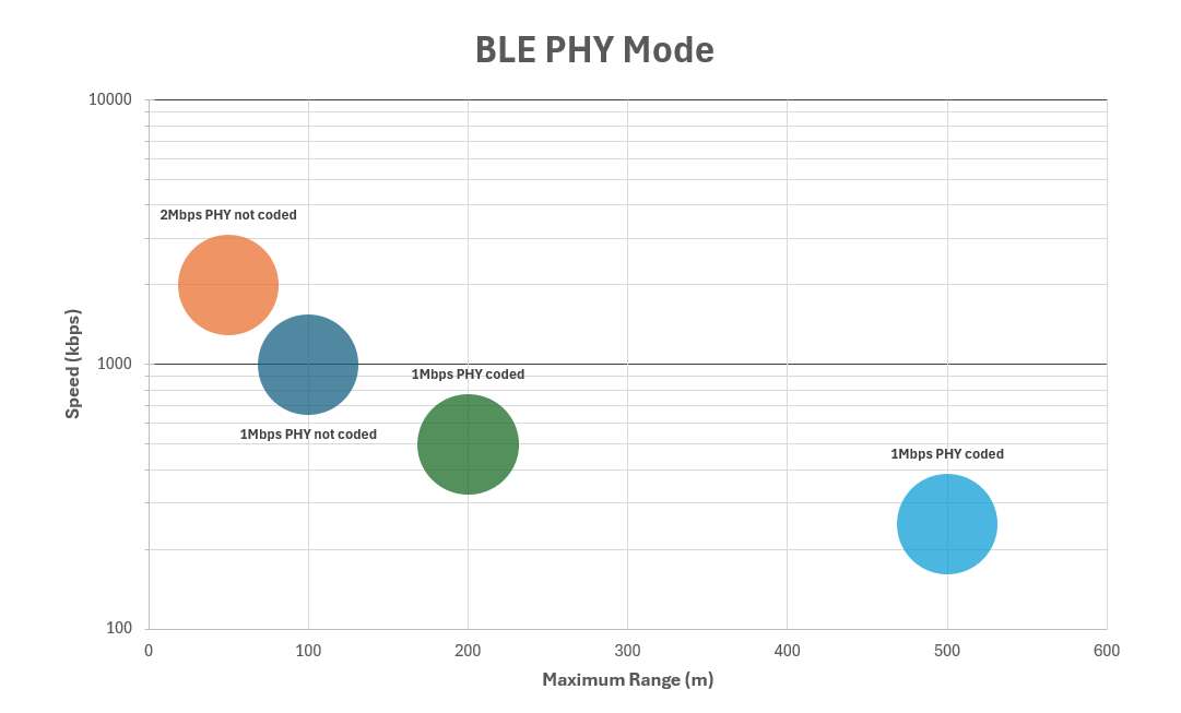
BLE buffer size
The 0x3333:0x2D [BLE maximum buffer age ms] object defines the maximum time, in milliseconds, that the CANlink® wireless 4000 buffers CAN data before transmitting it over BLE.
This setting balances transmission latency and data throughput. Lower values result in lower latency but higher transmission frequency. Higher values increase latency but allow more data to be sent per transmission.
The effective behavior also depends on the amount of CAN traffic generated on the bus.
In typical configurations with a CAN baud rate of 500 kbit/s and a bus load of approximately 50%, a buffer age of 5 ms provides a balanced compromise.
BLE whitelist
The BLE whitelist restricts incoming BLE connections to devices explicitly listed in a predefined allow list. It provides a simple access control mechanism for BLE connections.
The whitelist is evaluated only when BLE is enabled (0x3008:0x09 [BLE Enable]).
Enable the whitelist
The whitelist is enabled by default.
By default, 0x3009:0x0B [BLE Whitelist - Enable] is set to 1, which enables whitelist enforcement.
When enabled, the device accepts BLE connection requests only from devices listed in the whitelist.
Up to eight whitelist entries are available.
Each whitelist entry defines a DeviceName for which incoming connection requests are accepted.
The DeviceName must be between 4 and 25 bytes long.
On CANlink® wireless 4000 and CANlink® mobile 3600 devices, the DeviceName corresponds to the value of 0x3009:0x05 [BLE Devicename] on the connecting device.
DeviceName for whitelist comparison are limited to 15 characters and must match exactly, or use the device's MAC address.
Info
For non-Proemion devices, the DeviceName typically corresponds to the device name reported by the operating system.
On Windows systems, the DeviceName typically matches the computer name.
You can find this value under Settings > System > About.
Important
When the whitelist is enabled, only devices listed in the whitelist can establish a BLE connection.
DeviceName for whitelist comparison are limited to 15 characters and must match exactly, or use the device's MAC address.
The following objects define the available whitelist entries:
| Object Index | Object Name |
|---|---|
0x3009:0x0C |
BLE Whitelist - Entry 1 |
0x3009:0x0D |
BLE Whitelist - Entry 2 |
0x3009:0x0E |
BLE Whitelist - Entry 3 |
0x3009:0x0F |
BLE Whitelist - Entry 4 |
0x3009:0x10 |
BLE Whitelist - Entry 5 |
0x3009:0x11 |
BLE Whitelist - Entry 6 |
0x3009:0x12 |
BLE Whitelist - Entry 7 |
0x3009:0x13 |
BLE Whitelist - Entry 8 |
Warning
All whitelist entries are empty by default. Because the whitelist is enabled by default, this configuration rejects all incoming BLE connection requests. This behavior is intentional and provides a secure default configuration.
Since the whitelist has 8 entries, up to 8 distinct devices can be authorized. By default, no BLE connection requests are accepted because the whitelist is enabled and contains no entries.
Tip
Remember that only Wi-Fi supports more than one simultaneous connection- so only one of the items on this list will be connected at one time.
Disable the whitelist
With 0x3009:0x0B [BLE Whitelist - Enable] set to 0, whitelist enforcement is disabled.
In this state, any BLE device requesting a connection is accepted.
Warning
Disabling the BLE whitelist removes access control for incoming BLE connections.
When the whitelist is disabled using 0x3009:0x0B [BLE Whitelist - Enable], any BLE central device can establish a connection.
Disable the whitelist only if other measures ensure that unauthorized devices cannot reach the BLE connection range.
This may be acceptable in environments with physical access restrictions, such as controlled or enclosed areas.
BLE peripheral
When operating as a BLE peripheral, the device advertises services that expose data endpoints, referred to as characteristics. A BLE central device scans and connects to the peripheral to exchange the data.
Proemion bridge service
The Proemion bridge service is the BLE service used to exchange CAN data. A BLE central device scans for this service, connects to it, and uses it for data transfer.
The service UUID is:
CAEC2DB0-0000-426D-B4FB-61B67CE2054C
The service exposes two characteristics.
| Characteristic UUID | Name | BLE properties | Description |
|---|---|---|---|
CAEC2DB0-0001-426D-B4FB-61B67CE2054C |
ReceiveData | WriteWithoutResponse | Receives data sent from the central device to the peripheral. |
CAEC2DB0-0002-426D-B4FB-61B67CE2054C |
TransmitData | Notify | Sends data from the peripheral to the central device using notifications. |
After connecting to the service, the central device can:
- Subscribe to notifications on the
TransmitDatacharacteristic. - Write data to the
ReceiveDatacharacteristic.
Data sent by the device is delivered to the central as BLE notifications.
Data sent by the central device is written to the ReceiveData characteristic.
Note
All data is transferred using the Proemion Byte Command Protocol.
For more information, see Byte Command Manual.
Configure device as a BLE peripheral
To operate the device as a BLE peripheral, configure the CANopen objects listed below. This configuration enables gateway operation between the CAN network and a BLE central device.
After applying the configuration, restart the device to activate BLE advertising.
| Object | Name | Value | Notes |
|---|---|---|---|
0x3008:0x02 |
WiFi Enable | 0 |
Disabled |
0x3008:0x03 |
Bluetooth Enable | 0 |
Disabled |
0x3008:0x09 |
BLE Enable | 1 |
Enabled |
0x3011:0x15 |
Connection Direction Configuration/Server or Client 2 | 2 |
Server enabled |
0x3011:0x16 |
Connect Type 2 | 3 |
BLE |
0x3009:0x05 |
BLE Devicename | ProemionBLE |
Set to appropriate name |
Ensure that the device is configured with a valid and unique CANopen Node ID for the CAN network. After the next restart, the device advertises the Proemion bridge service and is ready to accept BLE connections.
CAN-CAN-BLE bridge
A CAN-CAN-BLE bridge provides a wireless connection between two CAN networks using BLE. This configuration can be used as a substitute for CAN cabling in low-traffic scenarios, such as drag chains or remote control units.
Due to limited bandwidth, a BLE-based CAN-to-CAN bridge is not suitable for high CAN bus loads.
Configure a CAN-CAN-BLE bridge
To configure a CAN-CAN-BLE bridge, one device operates as a BLE central and the other as a BLE peripheral. Configure the CANopen objects as shown below.
| Object | Name | BLE central | BLE peripheral | Notes |
|---|---|---|---|---|
0x3008:0x02 |
WiFi Enable | 0 Disabled |
0 Disabled |
|
0x3008:0x03 |
Bluetooth Enable | 0 Disabled |
0 Disabled |
|
0x3008:0x09 |
BLE Enable | 1 Enabled |
1 Enabled |
|
0x3011:0x16 |
Connect Type 2 | 3 BLE |
3 BLE |
|
0x3011:0x15 |
Connection Direction Configuration/Server or Client | 3 Client Enabled |
2 Server Enabled |
|
0x3009:0x0B |
BLE Whitelist - Enable | - | 0 Disabled |
Allow connection from the central device |
0x3009:0x05 |
BLE Devicename | - | ProemionBLE |
Set as required |
0x3011:0x1A |
BLE MAC Address or device name | ProemionBLE |
- | Must match the peripheral device name |
The above configuration is already sufficient for a connectivity test. Optionally, you can apply a whitelist entry using the following example configuration:
| Object | Name | BLE central | BLE peripheral | Notes |
|---|---|---|---|---|
0x3009:0x0B |
BLE Whitelist - Enable | - | 1 Enabled |
Enable whitelist enforcement |
0x3009:0x05 |
BLE Devicename | ProemionCentral |
(as above) | Set a unique name for the central device |
0x3009:0x0C |
BLE Whitelist - Entry 1 | - | ProemionCentral |
Allow the central device to connect |
After configuration and reboot, the BLE central device scans for and connects to the BLE peripheral specified in 0x3011:0x1A.
Analog Inputs
The CANlink® wireless 4000 has two inputs that can be configured as analog inputs.
Electrical details can be found in the Technical Data section, under Interfaces, and pinouts in Main Plug Connector.
Pin 4 and pin 5 of the connector are analog inputs, and also pin 8 (Terminal 15).
| Pin | Voltage Measurement range |
|---|---|
| 4 | 0 VDC to 15 VDC |
| 5 | 0 VDC to 15 VDC |
| 8 (Terminal 15) |
0 VDC to 36 VDC (Maximum measurement voltage is the Terminal 30 (Vcc) voltage). |
Reading Analog Inputs
The analog inputs can be read using CANopen requests.
The results are represented as a decimal voltage.
Analogue Input 1 (pin 4) can be read from 0x3340:0x01 [Analogue Input 1 (Filtered)].
Analogue Input 2 (pin 5) can be read from 0x3340:0x02 [Analogue Input 2 (Filtered)].
Terminal 15 (pin 8) can be read from 0x3333:0x66 [Clamp 15 Real 32 (Filtered)].
Additionally, a digital representation of this analog input can be read from 0x3333:0x01 [Clamp 15].
This is useful as logic to determine if the ignition is switched on, or off.
| Value | Meaning |
|---|---|
0 |
Input state low (< 2.5 V) |
1 |
Input state high (> 5.5 V) |
Info
The Analog Input values in the CANopen Object Dictionary are updated every 50ms.
The filtering is not configurable, and is done in hardware.
Analog Input PDO
A worked example of configuring the device to periodically send analog input values over the bus using PDOs is described in the CTO section.
Digital Output
It is possible to use the pin 7 digital output of the Main Plug Connector interface of the CANlink® wireless 4000.
There are two ways that this output can be used:
- Manual
- Wireless Connection Active
Manual Output
In this mode, the output can be switched manually by setting the value of an object in the Object Dictionary.
Set 0x3333:0x0F [Digital Output] to 0 to output a low voltage, and 1 to output high.
This value is volatile, so it must be configured by an external controller after each reboot.
Wireless Connection Active
This mode represents the state of a wireless connection by setting the pin 7 output appropriately: High when connected, and Low when not connected.
This value can represent one of each of the three wireless interfaces: WiFi, Bluetooth and BLE:
- For WiFi, set
0x3333:0x6F [Digital Output Connection Visualization Wifi]to0x01. - For Bluetooth, set
0x3333:0x6E [Digital Output Connection Visualization Bluetooth SPP]to0x01. - For BLE, set
0x3333:0x70 [Digital Output Connection Visualization BLE]to0x01.
In all cases, set the unwanted interface objects to 0x00 (disabled).
Output Physical Properties
Pin 7 switches the voltage applied to Pin 1 (Terminal 30, Vcc):
- The maximum output current is 500mA
- Maximum switching frequency is 10Hz
Switched by another device
An example of the Digital Output being switched by another device sending a CTO is contained in the CTO Walkthrough.
Power Management
Warning
To protect the device from damage, correct wiring and configuration of the power management settings is recommended.
The main purpose of the power management settings are to ensure that the device has a safe shutdown before the supply voltage (terminal 30/31) is disconnected.
The following subsections provide an overview of the individual power management functions.
There are three different conditions required for a CANlink® wireless 4000 to turn itself off.
- Sleep-on-no-CAN time is elapsed
- Time-to-sleep is elapsed
- Shutdown Delay Time is enabled and has elapsed after Terminal 15 goes low
The following objects are used to configure the Power Management functionality:
| Index | SubIndex | Object |
|---|---|---|
0x3333 |
0x08 |
Time in seconds to sleep mode |
0x3333 |
0x29 |
Sleep timer active flag |
0x3333 |
0x32 |
PMM Shutdown Delay Time |
0x3333 |
0x37 |
Power Management Shutdown Enable |
0x3333 |
0x41 |
PMM Sleep on no CAN time |
Sleep-on-no-CAN
The Sleep-on-no-CAN setting is used when the device should automatically enter sleep mode when there is no CAN messages received by the device on either CAN bus within a specified time period.
Object 0x3333:0x41 [PMM Sleep on no CAN time] is used to set the CAN message timeout sleep period.
The timer is restarted with every CAN message received.
- Set
0x3333:0x41to the desired timeout in milliseconds. -
The device will go to sleep when
- no CAN message has been received in this time, and
- CLAMP15 is low
-
The device will automatically wake upon
- Any CAN traffic, or
- A high signal on CLAMP15.
Note
This value should be less than the timeout for 0x3333:0x80 [Wireless Interface Watchdog Period] (if enabled) to prevent the reset from the Wireless Watchdog resetting this counter.
See Wireless Watchdog.
Time-to-sleep
Object 0x3333:0x08 [Time in seconds to sleep mode] is used to set the sleep timeout period.
This is volatile (reset every boot), and must be set by an external controller every time the device should sleep.
Essentially, this value tells the device “Go to sleep (x) seconds after receiving the last CAN message when the ignition is off”.
This timer is restarted with every CAN message, and every change to CLAMP15.
- Set
0x3333:0x08to the desired timeout in seconds. -
The device will go to sleep
- After this period has elapsed with no CAN messages on either bus, and
- CLAMP15 is low, and
0x3333:0x29 [Sleep timer active flag]is set to0x01
-
The device will automatically wake upon
- Any CAN traffic, or
- A high signal on CLAMP15
Tip
The 0x3333:0x08 [Time in seconds to sleep mode] function will be disabled upon boot, and must be enabled again to occur.
Shutdown Delay Time (Terminal 15 Monitoring)
Object 0x3333:0x32 [PMM Shutdown Delay Time] is used to set the ignition timeout period.
The device waits for a period of time after the ignition has been turned off (CLAMP15 turns low).
This timer is restarted with every CAN message, and every change to CLAMP15.
TO ENABLE
- Set
0x3333:0x32 [PMM Shutdown Delay Time]to the desired timeout in seconds. - Set
0x3333:0x37 [Power Management Shutdown Enable]to0x80.
The device will go to sleep this many seconds after:
- ignition is off (CLAMP15 is low), and
- no CAN message has been received
0x3333:0x37 [Power Management Shutdown Enable]is set to0x80
The device will automatically wake upon:
- Any CAN traffic on either CAN bus, or
- A high signal on CLAMP15
TO DISABLE
Set 0x3333:0x37 [Power Management Shutdown Enable] to 0x00.
Note
The recommended minimum period for 0x3333:0x32 [PMM Shutdown Delay Time] is 5s.
Power Management Summary
In cases, to enter sleep:
0x3333:0x32 [PMM Shutdown delay time]has a non-zero value, and0x3333:0x37 [Power Management Shutdown Enable]is set to0x80, and- CLAMP15 must be low, and
- no CAN message has been received in the
0x3333:0x32 [PMM Shutdown delay time]period.
The device will automatically wake upon:
- Any CAN traffic on either CAN bus, or
- A high signal on CLAMP15
These three Sleep configurations operate simultaneously.
Wireless Watchdog
If a wireless connection is unreliable, one way to mitigate the unintended loss of connection is to use a feature that monitors the continuity of the connection, and reboots the device if the connection or data flow has not been maintained for a configurable amount of time.
After restart, the device will attempt to re-establish the connection.
Note
This feature is not needed under normal conditions.
It should be enabled only when investigating an issue, and should not be required during typical use.
Info
If the device encounters conditions that hinder or prevent data transmission, it may automatically reboot to restore functionality and resume transmission as soon as conditions improve.
In operation, a timer maintains a counter to measure the period since the last received wireless packet or correctly connected state.
If this period exceeds a user-configurable value, the device reboots.
This counter can be checked to verify operation, and is reset back to zero on every incoming wireless packet, and the monitoring continues.
Object Dictionary parameters
-
0x3333:0x80 [Wireless Interface Watchdog Period]
The period in seconds after which the device restarts after no wireless packets received, or no connection.
A period up to 65,535 seconds (over 18 hours) can be specified. -
0x3333:0x81 [Wireless Interface Watchdog Tick]
This value increments every second (if the feature is enabled) up to the value in0x3333:0x80. -
0x3333:0x82 [Wireless Interface Watchdog No Connection]
The number of times the device has restarted due to this feature because of no connection for the entire period. -
0x3333:0x83 [Wireless Interface Watchdog No Data]
The number of times the device has restarted due to this feature because of no data received (but with a valid connection) for the period. This could be useful for issue investigation. -
0x3333:0x84 [Wireless Interface Watchdog Restarts Count]
This is the sum of both0x82and0x83.
Set Parameters
Set 0x3333:0x80 [Wireless Interface Watchdog Period] to the value in seconds of the duration before reboot if either:
- no wireless traffic is received, or
- no connection has been made.
A value of 0 disables this feature, and is the default.
The minimum value that can be set is 90 (seconds).
The recommended minimum time is 120 seconds to prevent unnecessary reboots before a connection can be established.
Also, this period must be greater than the 0x3333:0x08 [Time in seconds to sleep mode] in order for the Sleep function to work.
Every write to this object applies the new period immediately and resets all counters (0x81, 0x82, 0x83, 0x84).
Tip
This object is non-volatile, so will remain functional until disabled by writing 0 to 0x3333:0x80.
(Or a factory reset).
Check Watchdog operation
When enabled, periodically (every few seconds) read 0x3333:0x81 [Wireless Interface Watchdog Tick].
The value will increase every second until reaching the Wireless Interface Watchdog Period, indicating that the function is operating.
Verify Watchdog action
-
Check
0x3333:0x84 [Wireless Interface Watchdog Restarts Count]value. -
Set
0x3333:0x80 [Wireless Interface Watchdog Period]to120. -
Make no connection to the device.
-
After 120 seconds, the device will reset:
a. Both LEDs briefly turn off
b. Both
0x3333:0x82 [Wireless Interface Watchdog No Connection]and0x3333:0x84 [Wireless Interface Watchdog Restarts Count]will increment by one to indicate that the Watchdog was the reason for the reset. -
The device continues to operate in this mode, incrementing the
0x3333:0x81counter every second; the0x3333:0x84every two minutes, and waiting for traffic to be received.
Indicator Element (LED)
The front of the device features two RGB LEDs for indicating function and status.
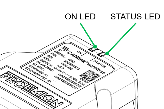
The following table shows possible ON LED states:
| ON Color | Indication | Meaning |
|---|---|---|
| - | Off | Device is switched off or in sleep mode. For more information, read Power Management. |
| Green | Slow Blinking | Device is in update mode and ready to receive an application firmware. The STATUS LED is blinking in parallel. |
| Green | Fast Blinking | Firmware flashing process. The STATUS LED is blinking in parallel. |
| Green | On | Device is switched on, terminal 30 voltage in permitted range (>= 6 and < 36 V). |
| Red | On | Device is switched on, terminal 30 voltage outside permitted range (< 6 or >= 36 V). |
| Orange | On | Device is in device reset mode (STATUS LED is also orange in parallel). |
The following table shows possible STATUS LED states:
| STATUS Color | Indication | Meaning |
|---|---|---|
| - | Off | Device is switched off or in sleep mode. For more information, read Power Management. |
| Green | Double Flash (200 ms on, 200 ms off, 200 ms on, 1000 ms off) |
Initialization of the Device. |
| Green | Triple Flash (200 ms on, 200 ms off) |
Device is ready for connection. |
| Green | On | Device is connected to a peer. There is no error. |
| Green | Slow Blinking | Device is in update mode and ready to receive an application firmware. The ON LED is blinking in parallel. |
| Green | Fast Blinking | Firmware flashing process. The ON LED is blinking in parallel. |
| Blue | Blinking | Data transfer active. |
| Blue | On | There is an wireless connection error. |
| Orange | Single Flash | Device received CANopen SDO request |
| Orange | On | CAN1 Error. |
| Red | On | CAN2 Error. |
Total Station Parsers
Total Stations are GPS tools that can send accurate location information to machines via the CANlink® wireless 4000. Both total station providers Topcon and Trimble are supported by the CANlink® wireless 4000.
The total station parser enables a Bluetooth connection between the Total Station Controller (TSC) and the CANlink® wireless 4000 to send the position data from the Total Station to the machine.
Object Dictionary Parameters
0x3330:0x01 [Selected Communication Protocol]
This selects the wireless protocol used for communication.
0x00: Proemion Byte Command Protocol0x01: Trimble Total Station Protocol0x02: Topcon Total Station Protocol0xFF: Auto-Detection Trimble/Topcon Protocol- Default value:
0x00
Note
For both Trimble and Topcon, Bit 29 (0x20000000) must be set to send a 29-bit CAN ID.
This bit must be reset (cleared) when sending 11-bit CAN IDs.
For example, if a message with the 29-bit ID 0x0CFFC201 is to be configured, the following value must be written to the object: 0x2CFFC201.
Enable Trimble Total Station Parser
The Trimble Total Station parser feature has been introduced in CANlink® wireless 4000 firmware version 2.2.0 for receiving and parsing Trimble Total Protocol.
The feature can be enabled by writing the value 1 into the object 0x3330:0x01 [Selected Communication Protocol].
The factory default value is 0 (disabled).
When the feature is activated, all other protocol messages such as the Byte Command Protocol (BCP) by Proemion or Topcon Total Station are discarded by the device. For more information on BCP, see Byte Command Manual.
As soon as a valid Trimble protocol frame is received by the device via the wireless interface, the device parses the frame and passes the data to the CAN bus.
The Trimble parser breaks down the Trimble protocol frame (received wirelessly) into three CAN messages with individual message IDs and forwards them to the CAN1 interface.
Each of three CAN messages contain one of three values: Northing, Easting, and Elevation The message ID can be configured by the user via the following objects:
0x3330:0x10--- Trimble Northing CAN ID0x3330:0x11--- Trimble Easting CAN ID0x3330:0x12--- Trimble Elevation CAN ID
Enable Topcon Total Station Parser
The Trimble Total Station parser feature has been introduced in CANlink® wireless 4000 firmware version 2.3.0 for receiving and parsing Topcon Total Protocol.
The feature can be activated by writing the value 2 into the object 0x3330:0x01. The factory default value is 0 (disabled).
When the feature is activated, all other protocol messages such as the Byte Command Protocol (BCP) by Proemion or Trimble Total Station are discarded by the device.
As soon as a valid Topcon protocol frame is received by the device via the wireless interface, the device parses the frame and passes the data to the CAN bus.
The Topcon parser breaks down the Topcon protocol frame (received wirelessly) into three CAN messages with individual message IDs and forwards them to the CAN1 interface.
Each of three CAN messages contain one of three values: Northing, Easting, and Elevation The message ID can be configured by the user via the following objects:
0x3330:0x20--- Topcon Northing CAN ID0x3330:0x21--- Topcon Easting CAN ID0x3330:0x22--- Topcon Elevation CAN ID
Topcon data can be received by the CANlink® wireless 4000 when the Topcon device is set to 'Master', if the CANlink® wireless 4000 is configured as a Server.
Likewise, the Topcon device may be a 'Slave' if the CANlink® wireless 4000 is a Client.
| Topcon Role | CANlink® wireless 4000 Role |
|---|---|
| 'Master' (Client) |
'Slave' (Server) |
| 'Slave' (Server) |
'Master' (Client) |
Auto-Detection Protocol
The Auto-Detection Protocol feature has been introduced in firmware v2.3.0.
The automatic detection between Trimble or Topcon Total Station Protocol can be activated by writing the value 0xFF into the object 0x3330:0x01 [Selected Communication Protocol].
When this auto-detection mode is active, the device verifies the incoming frame over the wireless interface and automatically switches to the appropriate protocol.
The detected protocol remains as the active parser until the next device restart (simultaneous parsing of Trimble and Topcon protocols is not possible).
The auto-detection evaluates only the Trimble or Topcon protocol; the Proemion BCP is not considered.
Setting 0x3330:0x01 [Selected Communication Protocol] to 0x00 [Proemion Byte Command Protocol] re-enables the default behavior.
CTO / PDO
CTO / PDO
A Process Data Object (PDO) is used in CANopen for broadcasting high-priority control and status information, and consists of a single CAN frame and up to 8 bytes of pure application data.
This is one of the two primary modes of communication in CANopen: the other being SDO (Service Data Object).
Proemion has a proprietary and more flexible system for setting up PDOs - called a Custom Transmit Object (CTO) - for use with the Proemion Configurator.
Tip
CANopen standard PDOs cannot be configured using standard CANopen techniques for the CANlink® wireless 4000.
The more flexible CTO version is configured with the Proemion Configurator only.
Two Walkthroughs have been provided that demonstrate different possible uses for CTOs on the CANlink® wireless 4000.
CTO Demonstration 1
This demonstrates sending a PDO:
- On a Cyclic basis
- Cyclically if a condition is met
- On the occurrence of an event
- From one Client (Client2) via the MultiTalking Server to another Client (Client1)
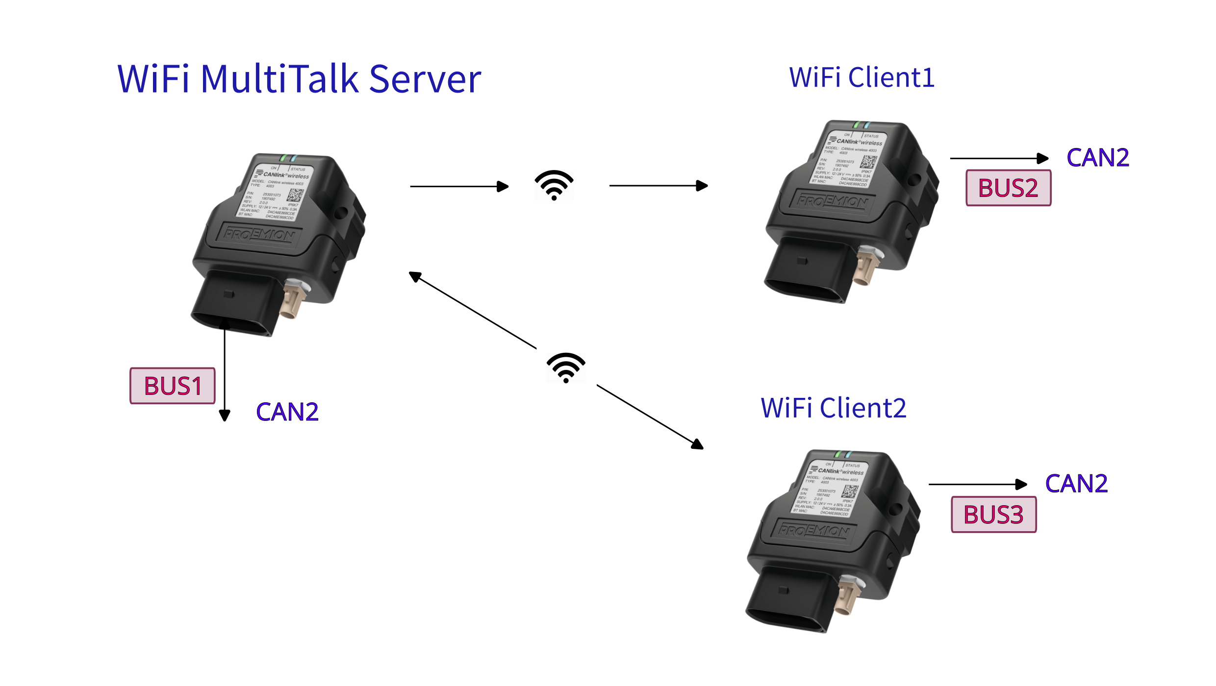
Follow the Walkthrough in the CTO Demonstration 1.
CTO Demonstration 2
This demonstrates sending a PDO:
- With Wi-Fi Automatic Channel Selection
- Switching the Digital Output of another device
- Sampling the device Analog Input
- Sending a PDO on State-Change of the Analog Input
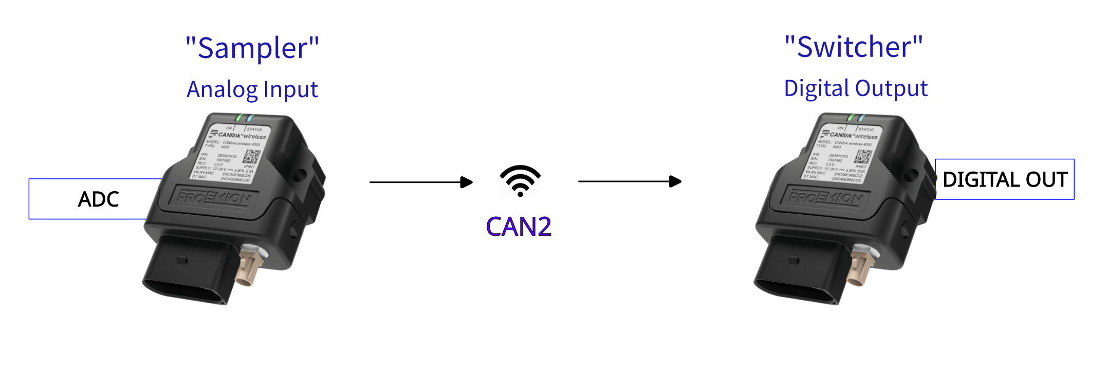
Follow the Walkthrough in the CTO Demonstration 2.
Disabling CTOs
To deactivate the CTO module, write 0x00 to object 0x2004:0x03 [Check Number].
A reboot is required to effect this change.
Enabling CTOs
If CTOs have been configured and disabled using the method described just above, the original CTO functionality can be restored by writing 0xFF to object 0x2004:0x03 [Check Number], and rebooting.
CTO Demonstration 1
Here we demonstrate several usages of the Proemion CTO implementation with a CANlink® wireless 4000 device.
Namely sending a message:
-
On a Cyclic basis
We will send the Analog 1 voltage every 2s from the Server.
Sent to Cob-ID0x300. -
Cyclically if a condition is met
The current state of the Wireless Watchdog Timer Counter every second after 30s (until it resets at 10 minutes) from the Server.
Sent to Cob-ID0x303. -
On the occurrence of event
Every time a WiFi Client connects to the Server on port 30,001, send a connection state from the Server.
Sent to Cob-ID0x306. -
From one Client (Client2) via the MultiTalking Server to another Client (Client1).
Client2 sends its serial number every 2s via CAN2 to Cob-ID0x206.
| PDO | From | Destination |
|---|---|---|
| Analog 1 Voltage | Server | 0x300 |
| Wireless Watchdog Timer Counter | Server | 0x303 |
| Wi-Fi Connection State | Server | 0x306 |
| Serial Number | Client 2 | 0x206 |
We will also demonstrate sending different payloads on these triggers.
The PDOs will be transmitted on the local CANbus, and to all wirelessly connected peers (and their local bus).
Note
This walkthrough demonstrates:
- CTO transmission
- Wi-Fi MultiTalk networking
See MultiTalk. - Wireless Watchdog
See Wireless Watchdog. - Analog voltage input
See Analog Inputs.
DOD files are available that mirror this walkthrough:
clw4001_SetupPDOs_Server.DODclw4001_SetupPDOs_Client1.DODclw4001_SetupPDOs_Client2.DOD
(See DOD files for more information).
Connection Diagram
Server
- firmware version ≥ 2.3
- Channel 36 (5GHz)
- SSID:
PDO_Server - MultiTalk enabled
MultiTalk - IP Address: 192.168.0.34
- Listening on Ports 30000 & 30001
- Node ID CAN1: 0d34
- Node ID CAN2: 0d35
- Sends Analog 1 voltage every 2s to COB-ID
0x300 - Sends Wireless Watchdog Timer Counter every second to COB-ID
0x303 - Sends Connection State every time a Client connects to port 30001 to COB-ID
0x306
Client 1
- firmware version ≥ 2.3
- Node ID CAN1: 0d44
- Node ID CAN2: 0d45
- Connects to port 30000
Client 2
- firmware version ≥ 2.3
- Node ID CAN1: 0d54
- Node ID CAN2: 0d55
- Connects to port 30001
- Sends device serial number every 2s to Cob-ID
0x206
Server Walkthrough
Firstly, let's set up the CTO configuration, then continue with configuring the device as a 5GHz Wi-Fi Server.
CTO Configuration
-
Ensure firmware of Server is ≥ v2.3.
-
Open the Proemion Configurator.
-
Open a New configuration.
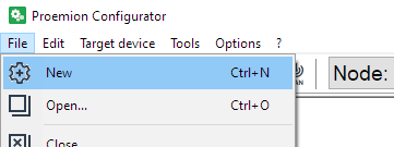
Figure 2: New Configuration -
You can see two devices under Local Connectivity Gateways
Select the correct one, according to your device.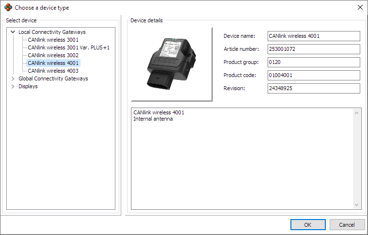
Figure 3: Choose Device Type -
Add DOD Information, and save as required
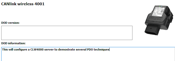
Figure 4: Save DOD Information -
Add a new 'Custom CAN Communication' folder.
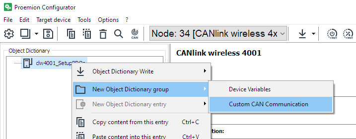
Figure 5: Custom CAN Communication -
Add 'Transmit PDO Messages (PDOs)' to this folder.
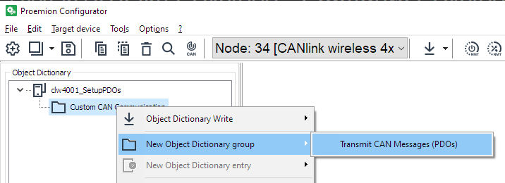
Figure 6: Transmit CAN messages -
Add the appropriate number of PDOs.
We are setting up three PDOs in this example:- Analog Voltage 1
- Wireless Connection State 2
- Wireless Interface Watchdog Tick
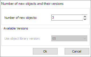
Figure 7: Add three PDOs -
Device variables must be added in order to be sent as PDOs.
In this example, we will send:-
Analog Voltage 1
-
Wireless Connection State 2
-
Wireless Interface Watchdog Tick
-
-
First, we must add the appropriate Device Variables.
Add a 'Device Variables' group.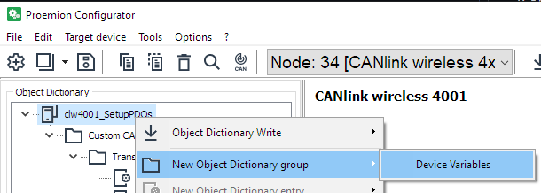
Figure 8: Add Device Variables -
As well as the three values we are transmitting, we base a decision on a forth Device Variable (Wireless Interface Watchdog Tick) - so add that too.
There should be the following Device Variables: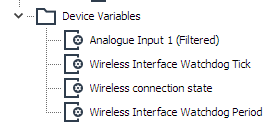
Figure 9: Device Variables Added -
Rename PDOs as required to match the function.
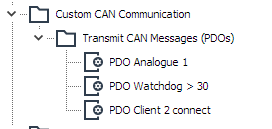
Figure 10: Rename Server PDOs
Set Cyclic Analog Voltage
We will configure the transmission of a single Device Variable in the Object Dictionary (OD) to be sent on a periodic basis.
It will be sent to COB-ID 0x300.
-
Click on the 'PDO Analogue 1' PDO under 'Custom CAN Communication'
-
Here we set the timing of the message.
a. Select the CAN bus for transmission (2).
This will be sent on the physical as well as wireless bus.
b. CAN-ID length
c. It is a cyclic message with a specified frequency.
d. Destination COB-ID.
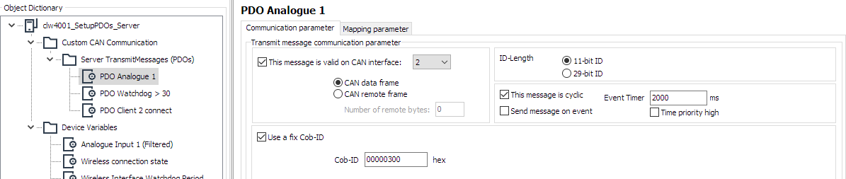
Figure 11: Set Analog Communication parameters -
Now that the transmission of the message has been defined, we specify the contents..
-
Click the 'Mapping parameter' tab to define the data to send.
Figure 12: Mapping parameter -
Currently, no data is mapped into this PDO.
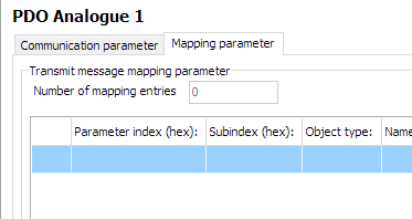
Figure 13: Analog Mapping parameter -
At the bottom is where we select the data to put into the message.
a. The data-type of the selected Device Variable is shown.
You can pack several Device Variables into the same PDO if they fit.
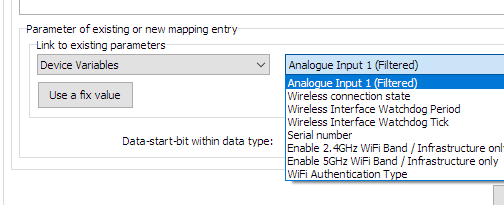
Figure 14: Analog Width
b. In this example, the Analogue Input is a 32bit real/float, so it takes up the entire PDO width.
You can align different data with the green fields.
c. Press 'New' when the field is correct. -
Items contained in this PDO are now listed.
(In this case, just one, but all data packed into the message will be listed).
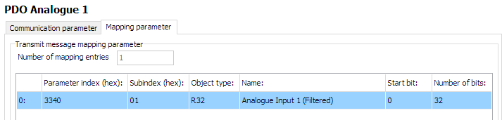
Figure 15: Analog Input Listed -
The first PDO has been configured.
Cyclically if a condition is met
This configuration sends a message periodically only if some condition is met.
This example will send current state of the Wireless Watchdog Timer Counter (how many seconds since initializing the watchdog timer) every second after 30s (until the device resets at 10 minutes) from the Server.
The message will be sent to Cob-ID 0x303.
-
Configure as in the image:
a. Suitable CAN bus (2)
b. Appropriate period (1000ms)
c. Select 'Cyclic' and 'Send message on event'
d. Configure destination COB-ID
e. The lower half of this page determines the condition that must be met in order to trigger sending the message (at the appropriate time).
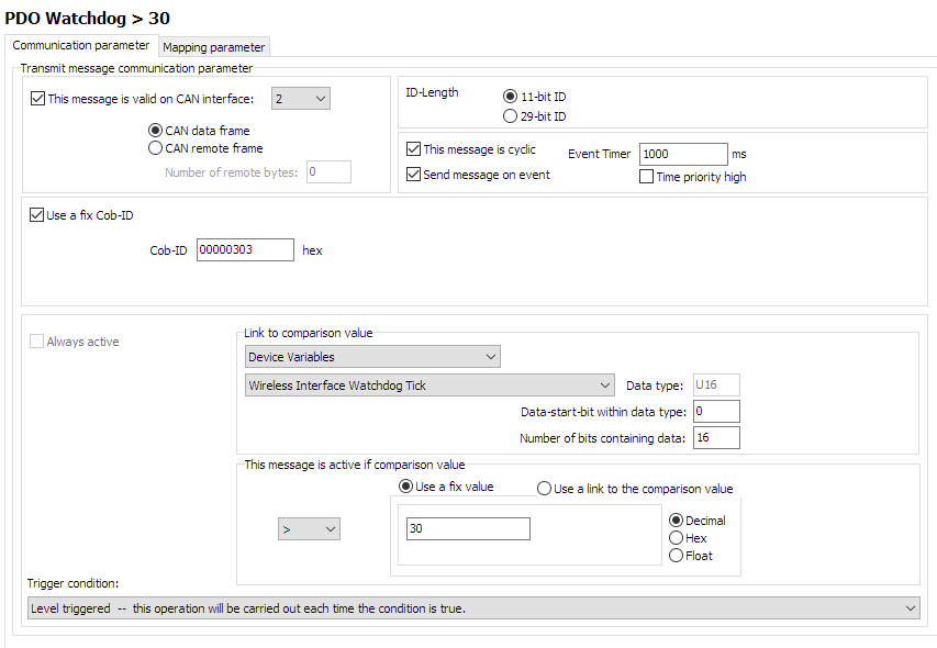
Figure 16: Server Watchdog PDO configuration
f. It can be seen that if the Device Variable 'Wireless Interface Watchdog Tick' is greater than 30, then the message can be sent.
Every time the timer is triggered, this evaluation will be checked.
Since this value increases every second, this message will begin to be transmitted 30 seconds after boot. -
Configure the contents in a similar way as we did before with the Analog Input CTO.
In this example, we will send the contents of the Tick itself, so we can see the value increasing every second.
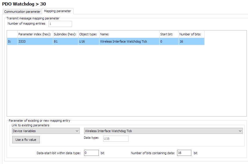
Figure 17: Server Watchdog PDO contents -
Enable the WIreless Interface Watchdog
Set0x3333:0x80 [Wireless Interface Watchdog Period]to 600 (decimal) to timeout after 10 minutes.
Event-driven message
Here we configure a message every time some event happens - regardless of time.
In this example, every time a Client device connects to port 30,001, we will send the Connection State to COB-ID 0x306.
-
Select only 'Send message on event'.
-
The comparison value will be the 'Connection State 2' which changes to
1on successful connection, then back to0when the connection is lost.
For this, we can use a fixed value for the comparison.
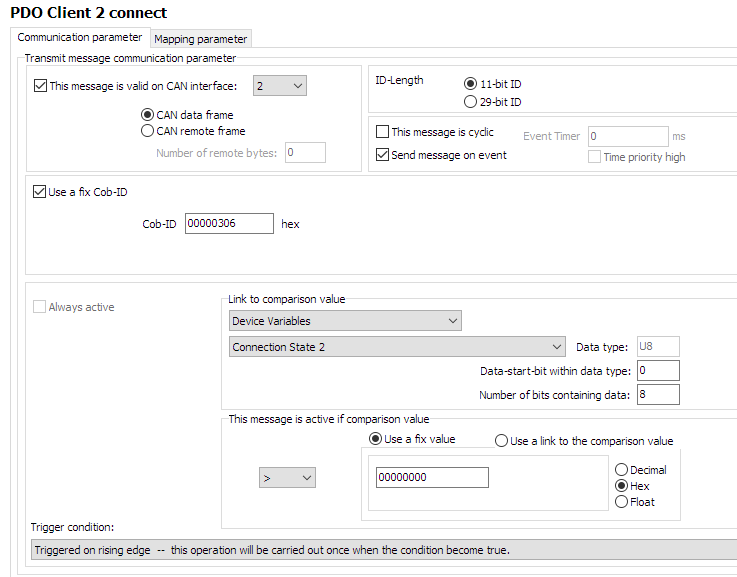
Figure 18: Server Connection PDO configuration -
Configure the contents of the message - in this case, the state of connection, itself.
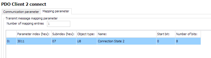
Figure 19: Server Connection PDO contents
5GHz Wi-Fi Server Configuration
Now that the DOD has been set up for transmitting CTOs, let's configure the device as a Server, so that Clients may connect to it:
For simplicity, create a new group 'ServerSetup' in the 'Device Variables' folder to contain device variables not involved in the CTOs.
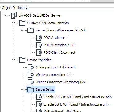
This will be basically a standard 5GHz Wi-Fi Server, with MultiTalk enabled.
Add the following Device Variables, with the following settings (change highlighted objects as necessary):
| Object | Setting | Notes |
|---|---|---|
0x3000:0x01 [Wi-Fi Operating Mode] |
0x02 [Mini Access Point] |
|
0x3000:0x10 [Enable 2.4GHz WiFi Band / Infrastructure only] |
0 Disabled |
|
0x3000:0x11 [Enable 5GHz WiFi Band / Infrastructure only] |
1 Enabled |
|
0x3008:0x03 [Bluetooth Enable] |
0 Disabled |
|
0x3008:0x09 [BLE Enable] |
0 Disabled |
|
0x3008:0x02 [WiFi Enable] |
1 Enabled |
|
0x3000:0x04 [WiFi Authentication Type] |
7 [WPA/WPA2 Mixed] |
|
0x3000:0x09 [WiFi DCHP Mode] |
2 [Server (WiFi MiniAP only)] |
|
0x3000:0x25 [WiFi Region] |
As Appropriate | |
0x3000:0x02 [WiFi SSID] |
PDO_Server | |
0x3000:0x05 [WiFi Authentication Key] |
ChocolateCake4Breakfast! | |
0x3000:0x0F [Access Point WiFi Channel / MiniAP only] |
36 |
|
0x3008:0x04 [MultiTalk Enable] |
1 [Enabled] |
For Client 2 -> Client 1 communications |
0x4054:0x10 [Forward all CANOpen messages] |
1 [Forward] |
|
0x3010:0x15 [Connection Direction Configuration/Server or Client 1] |
2 [Server enabled] |
For Client 1 |
0x3010:0x16 [Connect Type 1] |
1 [TCP Socket] |
For Client 1 |
0x3010:0x17 [URL Address/WiFi Client only 1] |
192.168.0.34 |
For Client 1 |
0x3010:0x18 [Socket Listen Port/WiFi only 1] |
30000 |
For Client 1 |
0x3011:0x15 [Connection Direction Configuration/Server or Client 2] |
2 [Server enabled] |
For Client 2 |
0x3011:0x16 [Connect Type 2] |
1 [TCP Socket] |
For Client 2 |
0x3011:0x17 [URL Address/WiFi Client only 2] |
192.168.0.34 |
For Client 2 |
0x3011:0x18 [Socket Listen Port/WiFi only 2] |
30001 |
For Client 2 |
0x4000:0x16 [CAN Message Output CAN2] |
1 [Start Msg. Output active] |
|
0x4050:0x03 [Node Id CAN 1] |
34 |
|
0x4050:0x04 [Node Id CAN 2] |
35 |
Program the Device
We have finished configuring the setup.
Now we must program the new configuration.
-
Establish a connection to the device.
Be sure to do a node-scan to select the correct device. -
Select '(Download) All Entries and Reset'.
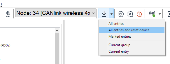
Figure 20: Download All Entries -
'Start'
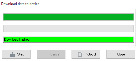
Figure 21: Download to Device -
Reboot the device.
Client 1 Walkthrough
Client 1 connects to the Server on port 30000.
It sends no PDOs, but receives them.
It is just a typical CLW4000 5GHz Wi-Fi bridge Client.
Add the following Device Variables, with the following settings (change highlighted objects as necessary):
| Object | Setting |
|---|---|
0x3000:0x01 [Wi-Fi Operating Mode] |
0x01 [Infrastructure] |
0x3000:0x10 [Enable 2.4GHz WiFi Band / Infrastructure only] |
0 Disabled |
0x3000:0x11 [Enable 5GHz WiFi Band / Infrastructure only] |
1 Enabled |
0x3008:0x03 [Bluetooth Enable] |
0 Disabled |
0x3008:0x09 [BLE Enable] |
0 Disabled |
0x3008:0x02 [WiFi Enable] |
1 Enabled |
0x3000:0x04 [WiFi Authentication Type] |
7 [WPA/WPA2 Mixed] |
0x3000:0x09 [WiFi DCHP Mode] |
1 [DHCP Client (WiFi infrastructure only)] |
0x3000:0x25 [WiFi Region] |
As Appropriate |
0x3000:0x02 [WiFi SSID] |
PDO_Server |
0x3000:0x05 [WiFi Authentication Key] |
ChocolateCake4Breakfast! |
0x3010:0x15 [Connection Direction Configuration/Server or Client 1] |
3 [Client enabled] |
0x3010:0x16 [Connect Type 1] |
1 [TCP Socket] |
0x3010:0x17 [URL Address/WiFi Client only 1] |
192.168.0.34 |
0x3010:0x18 [Socket Listen Port/WiFi only 1] |
30000 |
0x4050:0x03 [Node Id CAN 1] |
44 |
0x4050:0x04 [Node Id CAN 2] |
45 |
Program as above.
Client 2 Walkthrough
Client 2 connects to the Server on port 30001.
It sends its Serial Number as a PDO every 2s to Cob-ID 0x206.
Every device on the bus will receive this message, because the Server has enabled MultiTalk.
Device Variables
Add the following Device Variables, with the following settings (change highlighted objects as necessary):
| Object | Setting |
|---|---|
0x3000:0x01 [Wi-Fi Operating Mode] |
0x01 [Infrastructure] |
0x3000:0x10 [Enable 2.4GHz WiFi Band / Infrastructure only] |
0 Disabled |
0x3000:0x11 [Enable 5GHz WiFi Band / Infrastructure only] |
1 Enabled |
0x3008:0x03 [Bluetooth Enable] |
0 Disabled |
0x3008:0x09 [BLE Enable] |
0 Disabled |
0x3008:0x02 [WiFi Enable] |
1 Enabled |
0x3000:0x04 [WiFi Authentication Type] |
7 [WPA/WPA2 Mixed] |
0x3000:0x09 [WiFi DCHP Mode] |
1 [DHCP Client (WiFi infrastructure only)] |
0x3000:0x25 [WiFi Region] |
As Appropriate |
0x3000:0x02 [WiFi SSID] |
PDO_Server |
0x3000:0x05 [WiFi Authentication Key] |
ChocolateCake4Breakfast! |
0x3010:0x15 [Connection Direction Configuration/Server or Client 1] |
3 [Client enabled] |
0x3010:0x16 [Connect Type 1] |
1 [TCP Socket] |
0x3010:0x17 [URL Address/WiFi Client only 1] |
192.168.0.34 |
0x3010:0x18 [Socket Listen Port/WiFi only 1] |
30001 |
0x4050:0x03 [Node Id CAN 1] |
54 |
0x4050:0x04 [Node Id CAN 2] |
55 |
Also add 0x1018:0x04 [Serial Number] as a Device Variable in order to be able to send it in the next step configuring PDO.
| Object | Setting |
|---|---|
0x1018:0x04 [Serial Number] |
(Used for reading only) |
PDO configuration
Overview
- Add one PDO, rename as necessary
-
Setup a cyclic message, transmitting every 2 seconds to
0x206
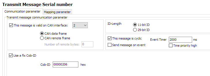
Figure 22: Client2 CTO Configuration -
Configure Mapping Parameter, using the
0x1018:0x04 [Serial Number]
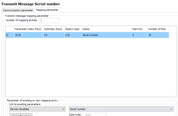
Figure 23: Client2 CTO Configuration
Steps
-
List is initially empty
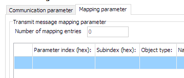
Figure 24: Client2 mapping -
Select 'Device Variables' for
Link to existing parameters
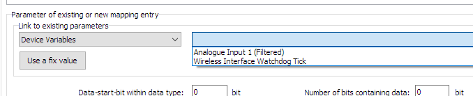
Figure 25: Client2 mapping -
Select appropriate Device Variable to transmit
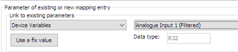
Figure 26: Client2 mapping -
Add number of databits as appropriate
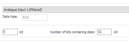
Figure 27: Client2 mapping -
Click "New" to add to mapping parameters
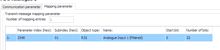
Figure 28: Client2 mapping
Set cyclic message
- Define period of message
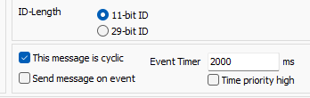
Testing CTO Demo
Firstly, write all configurations to the three devices:
- The Server CAN 2 Node ID should be
35. - Client 1 CAN 2 Node ID should be
45. - Client 2 CAN 2 Node ID should be
55.
Using your CANopen diagnostics tool of choice, you should be able to verify the following functions are operating as expected:
- Periodically
- Event-driven
- MultiTalk
Periodically
- The Server device will output the Analog voltage PDO to
0x300every two seconds on the virtual (wireless) connection as well as the physical CAN2 bus. -
The Server device will output the Wireless Interface Watchdog Tick value to
0x303:a. increasing by one every second.
b. starting after the value is greater or equal to 30.
c. until the device resets after ten minutes, at which point the process will begin again.
(There will have been 600 - 30 = 570 messages sent). -
Client2 will send its
0x1018:0x04 [Serial Number]every second to0x206to the CAN2 virtual (wireless) and physical bus.
Event-driven
- Every time Client2 is powered on and connects to the Server, the Server will output a single
0x3001:08 [Wireless connection state]PDO to0x306.
Power-off Client2 and back on again, and after a few seconds (while the connection is being established), the Server will output one more identical message.
MultiTalk
Since MultiTalk is enabled on the Server, every device connected to the CAN2 bus will receive the Client2 0x1018:0x04 [Serial Number] CTO.
This means every device connected wirelessly, and also all every CAN2 device connected physically to those devices.
Tip
When MultiTalk is enabled, CAN traffic can saturate the connection between all connected devices.
Consider enabling Filters.
CTO Demonstration 2
Here, we show how to configure sending a CTO wirelessly, which demonstrates:
- Wi-Fi Automatic Channel Selection
- Switching the Digital Output of another device
- Sampling the device Analog Input
- Sending a PDO on State-Change of the Analog Input
Outcome
This setup will have once device "Sampler" that reads its analog input, and switches the digital output of the other ("Switcher") device as the detected voltage changes between higher and lower than 12V.
This will be actioned with an SDO 'Expedited Transfer'.
Assumptions
- Supply voltage is 24V.
The output of the "Switcher" should be High when the voltage is greater than 12V on the "Sampler", and otherwise Low. - "Sampler" has Node-ID of 34; "Switcher" has 35.
- The CTO Demonstration 1 walk-through has been understood, as it introduces fundamental CTO concepts.
Basics
- Standard CAN2.0 PDO payload is 8 bytes.
"Sampler" Setup
This is the device that reads its analog input, and sends appropriate CTOs depending on the value.
We want to write one byte into the "Switcher" Object Dictionary, which will switch the Digital Output state.
Calculate the message bytes
Refresher
SDO Message Structure
| Byte | Description |
|---|---|
| 0 | Command byte (contains CCS, expedited flag, size indicator) |
| 1 | Index low byte |
| 2 | Index high byte |
| 3 | Subindex |
| 4–7 | Data (up to 4 bytes, depending on flags) |
Command Byte Breakdown
This byte encodes the Client Command Specifier (CCS) and control flags:
- Bits 7–5: CCS (3 bits)
- Bit 4: Reserved
- Bits 2–3: Number of unused bytes in data field
- Bit 1: Expedited transfer (1 = yes)
- Bit 0: Size indicated (1 = yes)
CCS values
| Value | Meaning |
|---|---|
| 1 | Initiate download request |
| 2 | Initiate upload request |
| 3 | Upload response |
| 4 | Download response |
| 5 | Abort transfer |
So the final Command Byte can be calculated of:
Command Byte summary
| Value | Meaning |
|---|---|
| 0x20 | CCS = 1 (Initiate download request) |
| 0x0C | Three unused bytes |
| 0x02 | Expedited transfer |
| 0x01 | Size Indicated |
| 0x2F | Final value |
(Assume that we want to turn on the Digital Output for this initial calculation).
-
Set the COB-ID to send to Node-ID 35 (decimal).
SDO Rx =0x600+ Node-ID
With the "Switcher" Node-ID of 35 (decimal), we set the COB-ID to0x623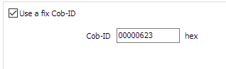
Figure 2: Set COB-ID -
The Command specifier as calculated above for 'SDO Expedited Download (write 1 byte)' is
0x2F.
This is the first byte in the message data. -
The Index and Sub-Index for the Digital Output is
0x3333:0x0F. -
To enable the Digital Output, we write a
1.
Putting these together, the bytes to transmit are:
| Value | Byte number | Meaning |
|---|---|---|
0x2F |
Byte 0 | Command specifier Expedited Download (write 1 byte) |
0x3333 |
Byte 1 - 2 | Index |
0x0F |
Byte 3 | Sub-Index |
0x01 |
Byte 4 | Data to write (Enable) |
The CANlink® wireless 4000 does not have an Operations Manager as the CANlink® mobile 3600 does, so we must store these values in the Object Dictionary to be sent out in this PDO message.
There are five bytes to send, which could be two 32bit values, and one more byte.
We can simply pick any unused objects in the Object Dictionary, write the desired values into them, and then send these objects with this message is triggered.
In this example, we will use the following objects:
0x3330:0x10 [Trimble X coordinate CAN ID]0x3330:0x11 [Trimble Y coordinate CAN ID]0x3330:0x12 [Trimble Z coordinate CAN ID]
Each are 32bit objects.
One PDO message sends eight bytes, so there will be two of these objects per message.
The messages are identical, apart from Byte 4, which changes between 1 for output High, and 0 for output Low.
Therefore we can use the same first object in both messages, and just change the last object depending on the desired state of the Digital Output in the "Switcher" device.
(We could use any other one byte object for the 'enable/disable' Byte 4 - but for consistency, we chose this for this example).
Add objects for CTO
In order for the logic to function, some Objects must be added to the Configuration as Device Variables.
For clarity, add them to a folder called CTOs.
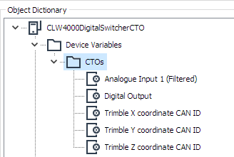
0x3340:0x01 [Analogue Input 1 (Filtered)]for measuring the voltage0x3333:0x0F [Digital Output]. This is the object on "Switcher" we request to change.0x3330:0x10 [Trimble X coordinate CAN ID]. Used for the first four bytes of the message.0x3330:0x11 [Trimble Y coordinate CAN ID]. Used for 'Enable'.0x3330:0x12 [Trimble Z coordinate CAN ID]. Used for 'Disable'.
Configure objects for CTO
In this diagram we show the bytes required in the message to enable the Digital Output in the "Switcher" device (Byte 4 is 0x01).
The bytes are transmitted in Little-Endian format, and the values are shown in the configuration as Big-Endian.
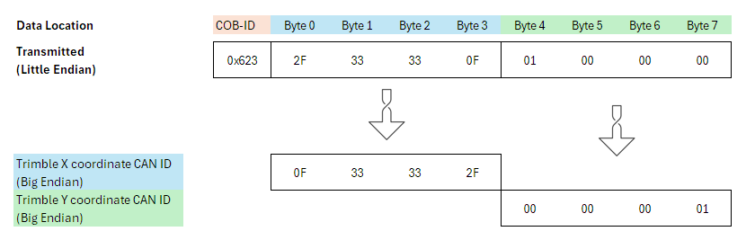
To transmit the bytes in the correct order, the 32 bit objects must be flipped to Little-Endian ordering.
The result is shown at the bottom of this diagram, which is what the values of those objects should be:
- Set
0x3330:0x10 [Trimble X coordinate CAN ID]to0x0F33332F - Set
0x3330:0x11 [Trimble Y coordinate CAN ID]to0x00000001 - Set
0x3330:0x12 [Trimble Z coordinate CAN ID]to0x00000000
(Writing0x00turns the Digital Output to Low).
Add PDOs
Now we can set up the PDOs — one for a High Digital Output, and one for Low.
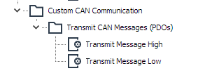
-
Add two Transmit Message PDOs by right-clicking on 'Custom CAN Communication'.
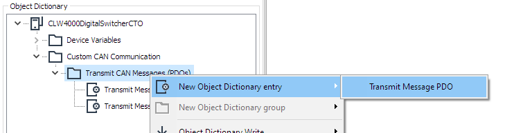
Figure 6: Add new PDO -
Name appropriately.
Configure Message High PDO
First, configure the 'Communication parameter' tab:
- Enable output on CAN 1.
- Set ID-Length to 11-bit ID.
- This event will be sent on an event (voltage rising or falling past 12V).
- Use a fix COB-ID
0x623.
The settings will look like the following:
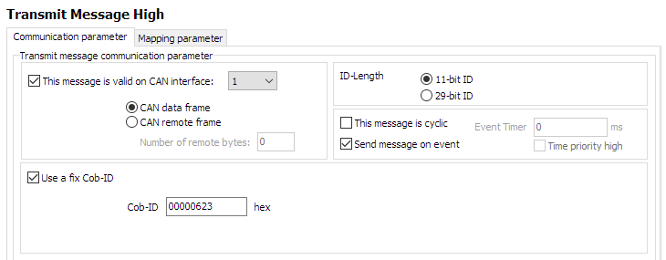
Next, the trigger condition:
-
The comparison value will be the
Analogue Input 1 (Filtered)on this device.
Select that object from the Device Variables that we have included in this configuration. -
Select a comparison to a fixed value (voltage) of
12.
If the value rises about this, the message should be sent. -
Ensure the comparison logic is 'greater than'
>. -
The trigger is set to 'rising edge' — the PDO is sent when the condition (voltage > 12) is true.
The final condition will look like the following:
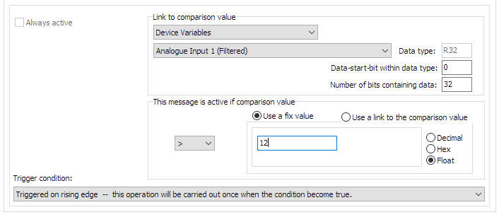
Next, the Mapping Parameter:
-
Select the 'Mapping parameter' tab.
-
Select the first bytes to form the final message (
Trimble X coordinate CAN ID)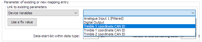
Figure 9: Select first bytes -
We want all 32 bits to be in this message, so the 'Data-start-bit within data type' stays as zero.
'Number of bits containing data' is 32 (all bytes in the object). -
Click 'New' to add.
The first parameter has been added, and will look like the following:
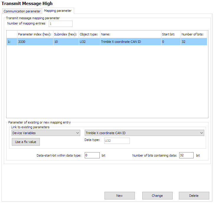
Next, add the remaining data bytes:
- Just as before, add
Trimble Y coordinate CAN IDto form the remaining four bytes.
The final 'Mapping Parameter' for the 'Transmit Message High PDO' are now:
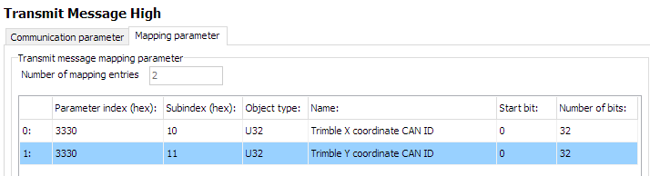
This PDO is now complete.
Configure Message Low
In a very similar way, we construct the 'Transmit Message Low' PDO.
The only difference is that we trigger on voltage falling below 12V, and send the Trimble Z coordinate CAN ID with value 0x00000000 to turn the Digital Output to Low.
This changes the value written to the Digital Output object to 0 — Low.
We can simply check for a false condition on the same comparison for this PDO:
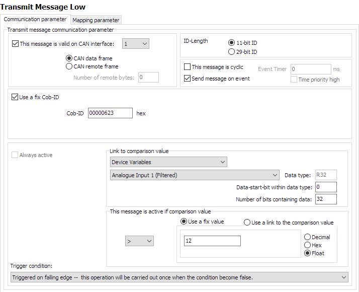
The mapping is essentially the same, but substituting Trimble Z coordinate CAN ID for Trimble Y coordinate CAN ID:
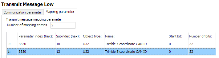
The CTO configuration is finished.
Now just set the device to connect to the "Switcher" device.
Network setup
We will connect to the "Switcher" device on 2.4GHz Wi-Fi band.
The following objects are required.
| Object | Setting |
|---|---|
0x3000:0x01 [Wi-Fi Operating Mode] |
0x01 [Infrastructure] |
0x3000:0x10 [Enable 2.4GHz WiFi Band / Infrastructure only] |
1 Enabled |
0x3000:0x11 [Enable 5GHz WiFi Band / Infrastructure only] |
0 Disabled |
0x3008:0x03 [Bluetooth Enable] |
0 Disabled |
0x3008:0x09 [BLE Enable] |
0 Disabled |
0x3008:0x02 [WiFi Enable] |
1 Enabled |
0x3000:0x04 [WiFi Authentication Type] |
7 [WPA/WPA2 Mixed] |
0x3000:0x09 [WiFi DHCP Mode] |
1 [DHCP Client (WiFi infrastructure only)] |
0x3000:0x25 [WiFi Region] |
As Appropriate |
0x3000:0x02 [WiFi SSID] |
PDO_Server |
0x3000:0x05 [WiFi Authentication Key] |
ChocolateCake4Breakfast! |
0x3010:0x15 [Connection Direction Configuration/Server or Client 1] |
3 [Client enabled] |
0x3010:0x16 [Connect Type 1] |
1 [TCP Socket] |
0x3010:0x17 [URL Address/WiFi Client only 1] |
192.168.0.35 |
0x3010:0x18 [Socket Listen Port/WiFi only 1] |
30000 |
0x4050:0x03 [Node Id CAN 1] |
34 |
"Switcher" Setup
This is the device that receives CTOs from the "Sampler", and switches its digital output appropriately.
The Node-ID is 35 decimal. "Sampler" has a Node-ID of 34 decimal.
Network setup
In contrast to the "Sampler" configuration - the "Switcher" is just a Wi-Fi Server (Access Point).
There is no configuration required related to PDOs — no effort is required to receive a PDO.
Consequently, only a typical Wi-Fi Server configuration is required:
| Object | Setting | Notes |
|---|---|---|
0x3000:0x01 [Wi-Fi Operating Mode] |
0x02 [Mini Access Point] |
|
0x3000:0x10 [Enable 2.4GHz WiFi Band / Infrastructure only] |
1 Enabled |
|
0x3000:0x11 [Enable 5GHz WiFi Band / Infrastructure only] |
0 Disabled |
|
0x3008:0x03 [Bluetooth Enable] |
0 Disabled |
|
0x3008:0x09 [BLE Enable] |
0 Disabled |
|
0x3008:0x02 [WiFi Enable] |
1 Enabled |
|
0x3000:0x04 [WiFi Authentication Type] |
7 [WPA/WPA2 Mixed] |
|
0x3000:0x09 [WiFi DHCP Mode] |
2 [Server (WiFi MiniAP only)] |
|
0x3000:0x25 [WiFi Region] |
As Appropriate | |
0x3000:0x02 [WiFi SSID] |
PDO_Server | |
0x3000:0x05 [WiFi Authentication Key] |
ChocolateCake4Breakfast! | |
0x3000:0x0F [Access Point WiFi Channel / MiniAP only] |
0 |
Automatic Channel Selection |
0x3010:0x15 [Connection Direction Configuration/Server or Client 1] |
2 [Server enabled] |
|
0x3010:0x16 [Connect Type 1] |
1 [TCP Socket] |
|
0x3010:0x17 [URL Address/WiFi Client only 1] |
192.168.0.35 |
|
0x3010:0x18 [Socket Listen Port/WiFi only 1] |
30000 |
|
0x4000:0x16 [CAN Message Output CAN2] |
1 [Start Msg. Output active] |
|
0x4050:0x03 [Node Id CAN 1] |
35 |
After boot, this device will wait for a connection request on port 30000, and accept one Client.
If the voltage fluctuates around the 12V value, a PDO will be received that write to the 0x3333:0x0F [Digital Output] object.
The output will be High if a 1 is written, and Low if 0 is written.
Operation
The following sections contain information on operating the device and the Proemion Configurator software.
Create Support Archive
If the Proemion Support team request further information, an archive in ZIP format of the configuration can be produced which can help diagnosis.
In the menu bar, select Help > Create support archive...
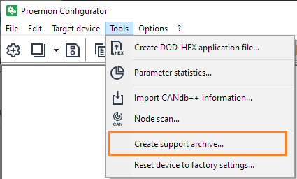
A dialog opens where you can save the configuration locally.
For more information, refer to the Proemion Configurator Manual.
CAN Functions
This chapter provides information on how to use and configure CAN functions.
CAN / CANopen
Note
You can find the CANopen objects documentation for configuring and operating the CANlink® wireless 4000 via CANopen in the Download Center under: 01_Proemion_Devices > 08_CANlink wireless 4000 > 01_Documentation.
There is an Electronic Data Sheet file (CANlink_wireless_4000_0.eds) and an HTML representation (CANlink_wireless_4000_0.html) provided.
The CANlink® wireless 4000 supports the transmission of pure CAN messages to another device. No direct protocol interpretation is configured in the firmware. This makes it possible to use the device for different applications with various CAN transport protocols. The protocol logic must be implemented in the other device (e.g. in the PC software). An example is the implementation within the CANopen section of the RM CAN Device Monitor Pro CANopen software.
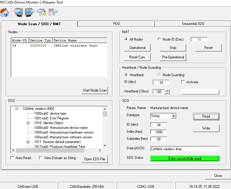
Enabling the CANopen Stack
The CANopen stack prevents the transmission of some CAN messages such as CANopen RX SDOs, TX SDOs, and emergency messages.
These messages are received by the device's CANopen stack and processed to the radio Interface without being forwarded on. It is possible to configure the device for connection control via CANopen.
In that case, the device does not transmit messages with certain CAN identifiers.
The following table shows messages that are used by the device but not transmitted when the CANopen stack is enabled.
| Type | CAN Identifier | Default configuration (Node ID 34) |
|---|---|---|
| TX SDO 1 | 0x580 |
0x5A2 |
| RX SDO 1 | 0x600 |
0x622 |
| Heartbeat/Boot-Up | 0x700 |
0x722 |
| NMT | 0x000 |
0x000 |
Boot-Up message
Directly after startup, the device optionally transmits a CANopen boot-up message with its own node ID.
Note
When this function is enabled, the device expects an acknowledge message from another bus participant.
If no acknowledge message is received, for instance while no other CAN bus participant is active, the LED changes to error mode according to chapter Indicator Element (LED).
CAN1
- To Enable Set bit 0 of
0x4054:0x03to 1 - To Disable Set bit 0 of
0x4054:0x03to 0
CAN2
- To Enable Set bit 0 of
0x4054:0x04to 1 - To Disable Set bit 0 of
0x4054:0x04to 0
CAN Filtering
The CANlink® wireless 4000 is equipped with eight (8) hardware CAN filters, which can be configured to block certain CAN IDs received on the CAN bus from being sent wirelessly to connected peers.
Note
Only CAN messages coming in from a physical CAN bus are processed through the filter system, if enabled. If the message matches, it is transmitted to all wireless peers.
All messages arriving on a wireless interface are put onto the appropriate CAN bus.
Blocking certain CAN IDs can reduce the volume of CAN messages transmitted over the wireless interface, typically done for the purpose of not exceeding the maximum message processing throughput of the device, or ensuring that the CAN bus only transmits certain CAN messages to another segment of that CAN bus.
This can be particularly advantageous when multiple devices are connected simultaneously, as in a MultPoint or MultiTalk configuration.
(See MultiPoint Connections).
In addition, preventing certain CAN IDs being transmitted wirelessly can provide some security from eavesdroppers of sensitive wireless traffic.
CAN Filter Concepts
Each one of the eight filters can be configured to either
-
allow multiple CAN IDs to pass; or
-
allow a single CAN ID with optional downsampling.
A CAN message that does not match the receiver filter of an online CAN object is passed on to the next active (enabled) filter and checked again.
Only messages that match are transmitted.
Downsampling
Downsampling is the process of preventing every message that matches a particular Filter & Mask from being transmitted, but instead, waiting a minimum durtime period before sending the next matching message.
The period between volume of matching messages can be set with
-
0x5024 [CAN1 object min rec time]for CAN1 (and0x5025for the volatile version) -
0x5034 [CAN1 object min rec time]for CAN2 (and0x5035for the volatile version)
All of these objects can be individually set for each of the eight CAN filters, and specify the period in milliseconds before another message is permitted to pass that filter, and be transmitted wirelessly.
The default is 0, which allows every message that matches the filter to be transmitted.
Summary
- Downsampling allows slowing down the frequency of transmissions that match a certain filter.
- The default is set to
0, which allows every matched message to be transmitted. - The value determines the minimum time in milliseconds before another message matching that filter can be transmitted.
Precautions
-
If more than one message matches a particular filter (see Filter Mask), enabling Downsampling can lead to confusing wireless traffic where some matching messages are not transmitted, while others are, depending on the timing of those messages.
This results from the Downsampling period preventing any matching message from being transmitted until that period expires.
For this reason, it is recommended to enable Downsampling only on filters that match one specific CAN-ID. -
Since a non-matching CAN-ID does not remove the message from the filter checking process (it is passed onto the next active filter), a message that matches a filter but is within the Downsampling period may be matched by a subsequent filter.
This can give confusing results, if a CAN-ID matches a filter that has a Downsample period defined and is transmitted more frequently than that period.
Careful design of the Filters can be required for an optimal outcome.
Filter Mask
Filter for Multiple CAN IDs (abstracted example)
A filter configured to allow multiple IDs needs to define which binary values are allowed to pass through each CAN ID bit position.
Only when all CAN ID bits pass, the CAN message is permitted to be transmitted.
We can think of the filter bit positions being set to one of the following values
0only a value of0passes1only a value of1passes- X either value passes (we don't care)
In the following abstract examples, we use the following representations
| Result | Symbol |
|---|---|
| PASS | P |
| BLOCK | B |
| EITHER | X |
Example 1 Multiple CAN IDs (abstracted)
Pass only 0x200, and 0x201
| Filter | 0 | 1 | 0 | 0 | 0 | 0 | 0 | 0 | 0 | 0 | X |
| Rx CAN ID 0x200 | 0 | 1 | 0 | 0 | 0 | 0 | 0 | 0 | 0 | 0 | 0 |
| Individual Bit Results | P | P | P | P | P | P | P | P | P | P | P |
| Overall Result : PASS |
| Rx CAN ID 0x201 | 0 | 1 | 0 | 0 | 0 | 0 | 0 | 0 | 0 | 0 |
| Individual Bit Results | P | P | P | P | P | P | P | P | P | P |
| Overall Result : PASS |
| Rx CAN ID 0x000 | 0 | 0 | 0 | 0 | 0 | 0 | 0 | 0 | 0 | 0 | 0 |
| Individual Bit Results | P | B | P | P | P | P | P | P | P | P | P |
| Overall Result : BLOCK |
| Rx CAN ID 0x001 | 0 | 0 | 0 | 0 | 0 | 0 | 0 | 0 | 0 | 0 | 1 |
| Individual Bit Results | P | B | P | P | P | P | P | P | P | P | P |
| Overall Result: BLOCK |
Example 2 Multiple CAN IDs (abstracted)
Pass only 0x200 0x201, 0x000, and 0x001
| Filter | 0 | X | 0 | 0 | 0 | 0 | 0 | 0 | 0 | 0 | X |
| Rx CAN ID 0x200 | 0 | 1 | 0 | 0 | 0 | 0 | 0 | 0 | 0 | 0 | 0 |
| Individual Bit Results | P | P | P | P | P | P | P | P | P | P | P |
| Overall Result PASS |
| Rx CAN ID 0x201 | 0 | 1 | 0 | 0 | 0 | 0 | 0 | 0 | 0 | 0 | 1 |
| Individual Bit Results | P | P | P | P | P | P | P | P | P | P | P |
| Overall Result PASS |
| Rx CAN ID 0x000 | 0 | 0 | 0 | 0 | 0 | 0 | 0 | 0 | 0 | 0 |
| Individual Bit Results | P | P | P | P | P | P | P | P | P | P |
| Overall Result PASS |
| Rx CAN ID 0x001 | 0 | 0 | 0 | 0 | 0 | 0 | 0 | 0 | 0 | 0 | 1 |
| Individual Bit Results | P | P | P | P | P | P | P | P | P | P | P |
| Overall Result PASS |
Special Case: Open Filter
With an open filter all incoming CAN messages are passed on to the processor regardless of their ID.
Either value passes off each bit passes the filter.
| Open Filter | X | X | X | X | X | X | X | X | X | X | X |
Filter for Single CAN ID (abstracted)
A filter configured to allow a single ID, needs to define the exact CAN ID, and whether any downsampling time is applied, i.e. the time for which messages will be blocked after receiving a single CAN message with this ID.
Example 3 Single CAN ID (abstracted)
Pass only 0x200
| Filter | 0 | 1 | 0 | 0 | 0 | 0 | 0 | 0 | 0 | 0 | 0 |
| Downsampling Time | 0ms |
| Rx CAN ID 0x200 | 0 | 1 | 0 | 0 | 0 | 0 | 0 | 0 | 0 | 0 |
| Individual Bit Results | P | P | P | P | P | P | P | P | P | P |
| Overall Result PASS |
| Rx CAN ID 0x201 | 0 | 1 | 0 | 0 | 0 | 0 | 0 | 0 | 0 | 0 | 1 |
| Individual Bit Results | P | P | P | P | P | P | P | P | P | P | B |
| Overall Result BLOCK |
Actual Filter Configuration Semantics
In the previous section it was discussed that there are essentially two
types of filters (multiple ID, single ID), but in fact each one of the
eight filters is configured via the following three (3) parameters
-
Filter Mask
Defines which received CAN ID bit positions are required to be checked against the same bit positions of the Filter ID (we call these bits "check Filter ID"), and which positions will be
regarded as "allowed to pass". -
Filter ID
For each bit position defined by the Filter Mask as "check Filter ID", the binary value of that position in the incoming CAN ID must match the binary value of the same position in the Filter ID, in
which case, the position will be regarded as "allowed to pass".
When each and every bit position of an incoming CAN ID is regarded as "allowed to pass", CAN messages with this CAN ID are passed onto the second stage of the filter, the Downsampling Time. -
Downsampling Time
The time the CAN receive channel remains closed after a single CAN message is received.
Example 4 Multiple CAN IDs (actual)
| Filter (abstracted) | 0 | 1 | 0 | 0 | 0 | 0 | 0 | 0 | 0 | 0 | X |
Pass only 0x200, and 0x201
| Filter Mask 0x7FE | 1 | 1 | 1 | 1 | 1 | 1 | 1 | 1 | 1 | 1 | 0 |
| Filter ID 0x200/0x201 | 0 | 1 | 0 | 0 | 0 | 0 | 0 | 0 | 0 | 0 | 0/1 |
| Downsampling Time | 0ms |
Messages
| Rx CAN ID 0x200 | 0 | 1 | 0 | 0 | 0 | 0 | 0 | 0 | 0 | 0 | 0 |
| Individual Bit Results | P | P | P | P | P | P | P | P | P | P | P |
| Overall Result:PASS |
| Rx CAN ID 0x201 | 0 | 1 | 0 | 0 | 0 | 0 | 0 | 0 | 0 | 0 | 1 |
| Individual Bit Results | P | P | P | P | P | P | P | P | P | P | P |
| Overall Result:PASS |
| Rx CAN ID 0x000 | 0 | 0 | 0 | 0 | 0 | 0 | 0 | 0 | 0 | 0 | 0 |
| Individual Bit Results | P | B | P | P | P | P | P | P | P | P | P |
| Overall Result:BLOCK |
| Rx CAN ID 0x001 | 0 | 0 | 0 | 0 | 0 | 0 | 0 | 0 | 0 | 0 | 1 |
| Individual Bit Results | P | B | P | P | P | P | P | P | P | P | P |
| Overall Result:BLOCK |
Example 5 Multiple CAN IDs (actual)
Pass only 0x200 0x201, 0x000, and 0x001
| Filter (abstracted) | 0 | X | 0 | 0 | 0 | 0 | 0 | 0 | 0 | 0 | X |
| Filter Mask 0x7FE | 1 | 1 | 1 | 1 | 1 | 1 | 1 | 1 | 1 | 1 | 0 |
| Filter ID 0x200 0x201 0x000 0x001 |
0 | 0/1 | 0 | 0 | 0 | 0 | 0 | 0 | 0 | 0 | 0/1 |
| Downsampling Time | 0ms |
Messages
| Rx CAN ID 0x200 | 0 | 1 | 0 | 0 | 0 | 0 | 0 | 0 | 0 | 0 | 0 |
| Individual Bit Results | P | P | P | P | P | P | P | P | P | P | P |
| Overall Result:PASS |
| Rx CAN ID 0x201 | 0 | 1 | 0 | 0 | 0 | 0 | 0 | 0 | 0 | 0 | 1 |
| Individual Bit Results | P | P | P | P | P | P | P | P | P | P | P |
| Overall Result:PASS |
| Rx CAN ID 0x000 | 0 | 0 | 0 | 0 | 0 | 0 | 0 | 0 | 0 | 0 | 0 |
| Individual Bit Results | P | P | P | P | P | P | P | P | P | P | P |
| Overall Result:PASS |
| Rx CAN ID 0x001 | 0 | 0 | 0 | 0 | 0 | 0 | 0 | 0 | 0 | 0 | 1 |
| Individual Bit Results | P | P | P | P | P | P | P | P | P | P | P |
| Overall Result:PASS |
Filter for Single CAN ID (actual)
For single ID filter, the Mask is always configured to 0x7FF (11-bit IDs) or 0x1FFF FFFF (29-bit IDs).
Downsampling can optionally be set.
In practice, is it possible to configure downsampling for filters that allow multiple CAN IDs to pass, but there is little value in doing so since this would most probably result in some IDs never being received in a non deterministic manner.
Example 6 Single CAN ID (actual)
Pass only 0x200
| Filter Mask 0x7FF | 1 | 1 | 1 | 1 | 1 | 1 | 1 | 1 | 1 | 1 | 1 |
| Filter ID 0x200 | 0 | 1 | 0 | 0 | 0 | 0 | 0 | 0 | 0 | 0 | 0 |
| Downsampling Time | 0ms |
Messages
| Rx CAN ID 0x200 | 0 | 1 | 0 | 0 | 0 | 0 | 0 | 0 | 0 | 0 | 0 |
| Individual Bit Results | P | P | P | P | P | P | P | P | P | P | P |
| Overall Result:PASS |
| Rx CAN ID 0x201 | 0 | 1 | 0 | 0 | 0 | 0 | 0 | 0 | 0 | 0 | 1 |
| Individual Bit Results | P | P | P | P | P | P | P | P | P | P | B |
| Overall Result:BLOCK |
Filter Configuration Cases & Considerations
Eight (8) or fewer CAN IDs
If eight (8) or fewer CAN IDs are required to pass through the filters for the application at hand, the only consideration is to understand what is the maximum acceptable sampling time for each CAN ID and adjust the Downsampling Time accordingly.
Nine (9) or more CAN IDs
If nine (9) or more CAN IDs are required to pass through the filters, The situation is more complex, because apart from the CAN IDs required to pass, there would most probably be other CAN IDs passing that are not actually required to pass, which can compromise performance or communication cost.
In such cases it advisable to evaluate every non-required CAN ID against all filters and compile a list a of "non-required PASS CAN IDs" so that the total number of CAN IDs per second can be calculated.
Tip
If transmitting more than one CAN ID per filter, try to arrange each mask to have the fewest numbers of set bits. In this way, the matching IDs are more tightly grouped, and fewer unwanted messages would pass than having fewer filters with more bits set.
You can use the CAN ID_MaskGenerator.xlsx file to calculate a CAN receive filter mask for multiple CAN IDs. The file is available in the Download Center under: 05_Utilities > 08_CAN ID Mask Generator.
Received CAN ID Evaluation
Rx CAN IDs are accepted (passed through the filter) if the following is TRUE
(Rx_ID & Filter_Mask) == (Filter_Mask & Filter_ID)
&: bitwise AND==: equality check
Configuring CAN Filters
The filters are located in the Object Dictionary at the following addresses.
They can be split into Volatile and Non-volatile objects.
Non-volatile CAN Filter objects:
| Location | Description |
|---|---|
0x5020 [CAN1 object filter settings] |
Non-volatile Receive Object ID |
0x5022 [CAN1 object mask settings] |
Non-volatile Receive Object ID Mask |
0x5024 [CAN1 object min rec time] |
Non-volatile Downsample time in ms |
0x5030 [CAN2 object filter settings] |
Non-volatile Receive Object ID |
0x5032 [CAN2 object mask settings] |
Non-volatile Receive Object ID Mask |
0x5034 [CAN2 object min rec time] |
Non-volatile Downsample time in ms |
Volatile CAN Filter objects:
| Location | Description |
|---|---|
0x5021 [Volatile CAN1 object filter settings] |
Receive Object ID settings that can be changed dynamically |
0x5023 [Volatile CAN1 object mask settings] |
Receive Object ID mask settings that can be changed dynamically |
0x5025 [Volatile CAN1 object min rec time] |
Downsample time in ms that can be changed dynamically |
0x5031 [Volatile CAN2 object filter settings] |
Receive Object ID settings that can be changed dynamically |
0x5033 [Volatile CAN2 object mask settings] |
Receive Object ID mask settings that can be changed dynamically |
0x5035 [Volatile CAN2 object min rec time] |
Downsample time in ms that can be changed dynamically |
Worked Examples
Given the information in this chapter, here we present an example of configuring several CAN filters.
We will configure only the non-volatile filters, but the principle is exactly the same for the volatile versions.
Points to remember
CAN object filter settings
These are the 0x50200x01 - 0x50200x08 (for CAN1), and 0x50300x01 - 0x50300x08 (for CAN2) objects.
- Bit 29 selects between an 11 and 29 CAN ID filter.
CAN object mask settings
These are the 0x50220x01 - 0x50220x08 (for CAN1), and 0x50320x01 - 0x50320x08 (for CAN2) objects.
-
If a bit in this object is set, the bit in the received message ID has to match the filter.
-
If a bit is reset (zero), the bit in the received message ID does not matter. ("Don't care").
CAN object min rec time
These are the 0x50240x01 - 0x50240x08 (for CAN1), and 0x50340x01 - 0x50340x08 (for CAN2) objects.
This object represents the minimum time period before allowing a subsequent message through the associated filter, in milliseconds.
If a message matches (and is therefore transmitted), at least this duration must past before another message that matches is transmitted.
This is also referred to as 'Downsampling'.
- If this value is set to 0, every message matching the filter will be received.
Tip
To prevent unintended data loss of other matching messages, only use Downsampling with filters for individual CAN identifiers.
Defaults
0x50200x01 [CAN1 object filter 0] is by default 0x00000000. This means all 11-bit CAN-IDs are matched.
0x50200x02 [CAN1 object filter 1] is by default 0x20000000. This means all 29-bit CAN-IDs are matched.
The rest of the filters are disabled with a 0x80000000. (Bit31 disables the filter when set).
0x50220x01 [CAN1 object mask 0] is by default 0x00000000. This means any value of the CAN-ID will be matched ("Don't care").
0x50220x02 [CAN1 object mask 1] is by default 0x00000000. This means any value of the CAN-ID will be matched ("Don't care").
So with the combination of these settings, every message will be matched, and therefore passed through to the wireless interface.
(The settings for CAN2 are exactly the same).
The following sub-section will permit only required messages through.
Worked Example One
CAN messages with a CAN identifier of 0x123 are received on the CAN bus.
These 0x123 messages match the filter, and are transmitted wirelessly.
All other CAN messages with a different CAN identifier are ignored and forwarded to the next filter for a possible match.
| Hex | Binary | |
|---|---|---|
| 11-bit CAN ID to match | 0x123 |
____ ____ ____ ____ ____ _001 0010 0011 |
| Filter | 0x123 |
0000 0000 0000 0000 0000 0001 0010 0011 |
| (match exactly this 11-bit message ID) | ||
| Mask | 0x07FF |
0000 0000 0000 0000 0000 0111 1111 1111 |
| (all bits must match) | ||
| Matching CAN messages | 0x123 |
0000 0000 0000 0000 0000 0001 0010 0011 |
| (transmitted) |
Configuration
-
Set
0x50200x01 [CAN1 object filter 0]to0x0000 0123 -
Set
0x50220x01 [CAN1 object mask 0]to0x0000 07FF
No specific Downsampling period is specified (the default is 0 which matches every message), so that is the complete filter configuration.
Worked Example Two
CAN messages with a CAN identifier of 0x123, 0x124 and 0x125 are received on the CAN bus.
We want to transmit all messages wirelessly.
All other CAN messages with a different CAN identifier are ignored and forwarded to the next filter.
| Hex | Binary | |
|---|---|---|
| 11-bit CAN ID to match | 0x123 |
____ ____ ____ ____ ____ _001 0010 0011 |
0x124 |
____ ____ ____ ____ ____ _001 0010 0100 |
|
0x125 |
____ ____ ____ ____ ____ _001 0010 0101 |
|
| Filter | 0x120 |
0000 0000 0000 0000 0000 0001 0010 0000 |
| Mask | 0x7F8 |
0000 0000 0000 0000 0000 0111 1111 1000 |
| (match these three 11-bit message IDs) | ||
| Matching CAN messages | 0x120 |
0000 0000 0000 0000 0000 0001 0010 0000 |
| (transmitted) | 0x121 |
____ ____ ____ ____ ____ _001 0010 0001 |
0x122 |
____ ____ ____ ____ ____ _001 0010 0010 |
|
0x123 |
____ ____ ____ ____ ____ _001 0010 0011 |
|
0x124 |
____ ____ ____ ____ ____ _001 0010 0100 |
|
0x125 |
____ ____ ____ ____ ____ _001 0010 0101 |
|
0x126 |
____ ____ ____ ____ ____ _001 0010 0110 |
|
0x127 |
____ ____ ____ ____ ____ _001 0010 0111 |
Configuration
-
Set
0x5020:0x01 [CAN1 object filter 0]to0x0000 0123
Because bit 29 is reset (value of0), this means the message is interpreted as an 11-bit CAN-ID.
This influences what we can use for the Mask value. -
Set
0x5022:0x01 [CAN1 object mask 0]to0x0000 07F8
Since the corresponding filter is defined for an 11-bit CAN-ID, we can leave the higher bits as0, because only 11-bit CAN-IDs will match.
No Downsampling is specified, so that is the complete filter configuration.
It can be seen that since the inverse of the mask 0x7F8 is 0x007, eight messages will be matched by this configuration, rather than our required three.
If this is not acceptable, a separate filter could be created for just the 0x123 message, as shown in Worked Example One, and another one for 0x124 and 0x125 with a mask of 0x7FC (111 1111 1100).
Object Dictionary Essentials
CAN baudrate
The baudrate of each CAN bus can be configured separately.
For setting CAN1 baudrate, the object is 0x4051:0x03.
For setting CAN2 baudrate, the object is 0x4051:0x04.
Both objects are configured in the same way.
| kb/s | Value |
|---|---|
| 10 | 8 |
| 20 | 7 |
| 50 | 6 |
| 100 | 5 |
| 125 | 4 |
| 250 | 3 (default) |
| 500 | 2 |
| 800 | 1 |
| 1000 | 0 |
For example, to set CAN1 baudrate to 1Mb/s, write 0 to 0x4051:0x03.
CAN bus error handling
There are two objects that may be used to alter the response of the CANlink® wireless 4000 when the CAN bus enters passive or error states.
-
0x4054:0x11is the period after which the device automatically resets the CAN controller to force-recover from PASSIVE or BUSOFF states.
This is0(disabled) by default.
Minimum valid value is 1000 (ms). -
0x4054:0x12drops all CAN data when in PASSIVE or BUSOFF state.
When the bus recovers, no old data will be sent wirelessly.
This is enabled by default.
If there is a CAN network issue that causes a bus error, enabling 0x4054:0x11 [CAN error recovery latency] can force the CANlink® wireless 4000 out of that state (at a period specified ), regardless of the state of other devices on that bus.
Typical Configurations
Setting the Wireless Interface
The three wireless interface options are
- Wi-Fi (TCP)
- Bluetooth (SPP)
- BLE
Unspecified Behavior
Only one wireless interface may be selected at a time.
All others must be disabled for correct operation.
All interfaces are disabled by default.
Details are explained in this section.
TCP
Wi-Fi (TCP) is the only interface that can connect to multiple peers at the same time.
As a result, the configuration for this mode differs from the others.
We firstly show the simple case a CANlink® wireless 4000 connected to another CANlink® wireless 4000 in 'Bridge Mode'.
NAMING
We use the 'Bridge Mode' to describe one CLW4000 connected as a wireless CAN bridge from one CAN bus to another.
This is distinguished from 'MultiPoint Mode' where a device is connected to more than one other wireless peer (so multiple CAN buses are connected together).
But we also use the term 'Gateway Mode' in this document to describe using a CANlink® wireless 4000 as wireless access to the CAN bus from another device (such as PC, or mobile phone).
From the perspective of the device there is no difference between 'Bridge' and 'Gateway' Modes both are a point-to-point single-peer connection
Bridge Mode
This is the typical use-case of the device - connecting two CAN buses together wirelessly.
We describe a typical (WPA2 authenticated) configuration of a Server and Client device to connect over Wi-Fi.
More information is available in the .eds file that was distributed with the firmware.
(Change highlighted text to suit)
| Step | Wi-Fi Server | Wi-Fi Client |
|---|---|---|
| Restore all default parameters | Set 0x1011:0x01 to 0x64616F6 |
Set 0x1011:0x01 to 0x64616F6 |
| WiFi Operating Mode | Set 0x3000:0x01 to 2Access Point mode |
Set 0x3000:0x01 to 1Infrastructure mode |
| WiFi SSID | Set 0x3000:0x02 to "CLW4000_Server" |
Set 0x3000:0x02 to "CLW4000_Server" |
| WiFi Authentication (as appropriate) |
Set 0x3000:0x04 to 7WPA/WPA2 Mixed |
Set 0x3000:0x04 to 7WPA/WPA2 Mixed |
| WiFi Password | Set 0x3000:0x05 to "CLW4000_Pass" |
Set 0x3000:0x05 to "CLW4000_Pass" |
| WiFi DHCP Mode | Set 0x30000x09 to 2Server (MiniAP only) |
Set 0x3000:0x09 to 1DHCP Client (Infrastructure only) |
| WiFi Region (as appropriate) |
Set 0x30000x25 to 2 EU (Default) |
Set 0x30000x25 to 2 EU (Default) |
| Access Point Channel | Set 0x3000:0x0F to one of - 1, 2, 3, 4, 5, 6, 7, 8, 9, 10, 11 (2.4GHz) - 36, 40, 44, 48 (5GHz) |
🚫 |
| Enable WiFi 2.4GHz Band | 🚫 | If Server channel is ≤ 11 - set 0x3000:0x10 to 1 - set 0x3000:0x11 to 0 |
| Enable WiFi 5GHz Band | 🚫 | If Server channel is ≥ 36 - set 0x3000:0x10 to 0 - set 0x3000:0x11 to 1 |
| Bluetooth Enable | Set 0x3008:0x03 to 0 Disable |
Set 0x3008:0x03 to 0 Disable |
| BLE Enable | Set 0x3008:0x09 to 0 Disable |
Set 0x3008:0x09 to 0 Disable |
| WiFi Enable | Set 0x3008:0x02 to 1 Enable |
Set 0x3008:0x02 to 1Enable |
| Connection Direction | Set 0x3010:0x15 to 2 Server enabled |
Set 0x3010:0x15 to 3Client enabled |
| Connect Type 1 | Set 0x3010:0x16 to 1 TCP Socket |
Set 0x3010:0x16 to 1 TCP Socket |
| WiFi IP Address | Set 0x3000:0x0A to "192.168.0.34" |
🚫 |
| Address of Socket Server | 🚫 | Set 0x3010:0x17 to content of object 0x30000x0A in Server device (above) |
| Node ID CAN 1 | Set 0x4050:0x03 to 34 |
Set 0x4050:0x03 to 44 |
| Node ID CAN 2 | Set 0x4050:0x03 to 35 |
Set 0x4050:0x03 to 45 |
MultiPoint Mode
This is a configuration in which more than two physically separate CAN buses are connected logically together via a Wi-Fi network.
See MultiPoint connections for information.
MultiPoint means that any CAN data:
- from the physical CAN bus of the Server is sent to each wirelessly connected peer, and
- from the CAN bus of any peer is sent to the Server.
It can be seen that data from the bus of one peer is not shared with other pairs.
No special configuration is required over and above that to establish a Bridge between two devices, as long as that device can connect.
In other words, when another CANlink® wireless 4000 device is added to the network, the Server will automatically send incoming CAN data to all peers. No additional configuration must be done to the Server.
Tip
When we talk about 'CAN bus' in a general sense, we refer to either of the two buses the CANlink® wireless 4000 supports.
Logically, they are treated in the same way, and very little distinction are made between them (apart from Node ID).
Therefore, when we discuss sending CAN data wirelessly, data from both buses will be sent wirelessly, and put onto the correct bus when received by the peer device.
Configuration
To establish more than one Client connection to a Wi-Fi Server, some configuration is required.
Typically, the first Client is connected with the following settings:
| Object | Server | 1st Client |
|---|---|---|
Access Point Mode0x3000:0x01 [Operating Mode] |
0x02 [Mini Access Point] |
0x01 [Infrastructure] |
WiFi SSID0x3000:0x02 |
as appropriate | as appropriate |
Authentication0x3000:0x04 [Authentication Type] |
0x07 [WPA/WPA2 Mixed] |
0x07 [WPA/WPA2 Mixed] |
Password0x3000:0x05 [WiFi Authentication Key](See Password Requirements) |
as appropriate | as appropriate |
Static IP Address0x3000:0x0A [WiFi IP Address] |
as appropriate | 🚫 |
DHCP0x3000:0x09 [DHCP Mode] |
0x02 [Server] |
0x01 [DHCP Client (WLAN infrastructure only)] |
RF channel0x3000:0x0F [WLAN - Access Point Channel] |
as appropriate | 🚫 |
| RF band. One of: - 0x3000:0x10 [Enable 2.4GHz WiFi Band / Infrastructure only]- 0x3000:0x11 [Enable 5GHz WiFi Band / Infrastructure only] |
🚫 | as appropriate |
IP Address0x3000:0x0A [IP Address] |
as appropriate | 🚫 |
Disable BT0x3008:0x03 [Bluetooth Enable] |
0x00 |
0x00 |
Disable BLE0x3008:0x02 [BLE Enable] |
0x00 |
0x00 |
Enable WiFi0x3008:0x02 [WiFi Enable] |
0x01 |
0x01 |
Server address0x3010:0x17 [EEP URL Address/WLAN Client only 1] |
🚫 | Value of 0x3000:0x0A [IP Address] in Server device |
Enable WiFi server0x3010:0x15 [EEP Connection Direction Configuration/Server or Client 1] |
0x02 [Server enabled] |
0x03 [Client enabled] |
Connection type0x3010:0x16 [EEP Connect Type 1] |
0x01 [TCP Socket] |
0x01 [TCP Socket] |
Socket Listen Port0x3010:0x18 [Socket Listen Port/WiFi only 1] |
(30000 by default) |
Value of 0x3010:0x18 [Socket Listen Port/WiFi only 1] in Server device |
There are different objects per Client connection. These have been highlighted in green.
By default each of the seven possible Client connections has a different default port:
| Connection | Object | Default Port |
|---|---|---|
| Client 1 | 0x3010:0x18 [Socket Listen Port/WiFi only 1] |
30 000 |
| Client 2 | 0x3011:0x18 [Socket Listen Port/WiFi only 2] |
30 001 |
| Client 3 | 0x3012:0x18 [Socket Listen Port/WiFi only 3] |
30 002 |
| Client 4 | 0x3013:0x18 [Socket Listen Port/WiFi only 4] |
30 003 |
| Client 5 | 0x3014:0x18 [Socket Listen Port/WiFi only 5] |
30 004 |
| Client 6 | 0x3015:0x18 [Socket Listen Port/WiFi only 6] |
30 005 |
| Client 7 | 0x3016:0x18 [Socket Listen Port/WiFi only 7] |
30 006 |
As we can see, the first Client connects by default to port 30000, which is the default port that the Server will open and listen on.
All Port numbers can be set to the same value. This is how this tutorial will continue.
The Server device must be configured for each Client connection.
Again, as can be seen, the settings for each Client are in a different object, from 0x3010 for Client one, through 0x3016 for Client seven.
Server Objects (0x3011 group) |
Server Value |
|---|---|
Enable WiFi server0x3011:0x15 [EEP Connection Direction Configuration/Server or Client 2] |
0x02 [Server enabled] |
Connection type0x3011:0x16 [EEP Connect Type 2] |
0x01 [TCP Socket] |
Socket Listen Port0x3011:0x18 [Socket Listen Port/WiFi only 1] |
30000 |
The second Client connection is configured exactly as in the prior table with the settings for the first Client.
After this Client device has been configured, three CANlink® wireless 4000 would be connected together:
For an additional Client connection, the values in the 0x3012 group. (And so forth):
Server Objects (0x3012 group) |
Value |
|---|---|
Enable WiFi server0x3012:0x15 [EEP Connection Direction Configuration/Server or Client 2] |
0x02 [Server enabled] |
Connection type0x3012:0x16 [EEP Connect Type 2] |
0x01 [TCP Socket] |
Socket Listen Port0x3012:0x18 [Socket Listen Port/WiFi only 1] |
30000 |
MultiTalk
This is a configuration in which more than two separate CAN buses are connected logically together, and all data is shared between all connected nodes. See MultiTalk connections for information.
The difference over MultiPoint is that incoming wireless data is also propagated to all other peers.
Since only one device (the Server) has more than one peer - only this device needs configuration.
When Wi-Fi connections have already been established, only one setting is required to enable MultiPoint.
| Step | Wi-Fi Server | Wi-Fi Client(s) |
|---|---|---|
Enable MultiTalk0x3008:0x04 [MultiTalk Enable] |
Set to 0x01 |
🚫 No configuration needed |
Bluetooth
See the Bluetooth section for details about configuring a Bluetooth Server and Client.
Bluetooth Low Energy (BLE)
See BLE for details about configuring a BLE Server and Client.
Bandwidth tuning
There are several factors determining how much data is sent wirelessly, and the timing of it:
-
Overall bandwidth
CAN messages per second -
Latency
How long (on average) does it take for a CAN message from this bus to appear on the bus of the remote peer -
Jitter
The variation in time delay between transmission and reception of a CAN message.
Note
As an example, a message that always takes exactly 9ms to appear on the peer bus would have:
Latency 9ms
Jitter 0
whereas another system where the messages took between 7 and 13ms to appear on the remote bus would have:
Latency 7ms
Jitter 6ms
The standard configuration maximises overall performance, but in the case of a particular requirement, various adjustments can be made through the Object Dictionary.
Several objects will be explored, below, that can influence the metrics above.
BT SPP maximum buffer age ms
Note
0x3333:0x2A [BT SPP maximum buffer age ms]
- This parameter defines the maximum time in ms after which buffered CAN data will be send over the Bluetooth connection.
- Default
10ms
Essentially, this defines the maximum time that data can wait before being sent over Bluetooth to a connected peer.
This value can be reduced (down to 1), which would be particularly noticeable in terms of latency on a low-bandwidth bus.
This time is started when the first message enters the buffer - and when timed-out, initiates the transmission of the buffered data.
Reducing this value prioritizes many small messages quickly over fewer larger messages less frequently.
This may have negative effects on the bus behavior.
Wi-Fi maximum buffer age ms
Note
0x3333:0x2B [WiFi maximum buffer age ms]
- This parameter defines the maximum time in ms after which buffered CAN data will be send over the Wi-Fi connection.
- Default 10 ms
This functions identically as the Bluetooth version does, above - but for the Wi-Fi interface.
BLE maximum buffer age ms
Note
0x3333:0x2D [BLE maximum buffer age ms]
- This parameter defines the maximum time in ms after which buffered CAN data will be send over the BLE connection.
- Default
10ms
This functions identically as the Bluetooth and Wi-Fi versions do, above - but for the BLE interface.
Maximum Bluetooth Packet Size
Note
0x3333:0x2C [Maximum BT SPP Packet Size]
- This parameter reflects the maximum transmitted packet size for a device configured for a Bluetooth interface.
Higher values allows higher throughput. - Default
640(bytes) - Maximum
854(bytes)
This value works in concert with 0x3333:0x2A [BT SPP maximum buffer age ms] to define the
- duration between data packets sent, and
- amount of data sent per packet
These two values could be considered in conflict
- A large packet size optimises for larger packets less frequently (at the expense of latency)
- A lower buffer age optimises for frequency of transmission over anything else.
- A smaller packet size would reduce average latency (in high traffic situations)
- In extremely high bandwidth applications, a high buffer age may be required.
Because of these conflicts, these OD values cannot be both maximized.
Careful tuning for a particular requirement may be needed.
Note
The default value of 640 has been determined to provide compatibility with CLW3000 devices.
When deployed into an environment with CLW3000 devices - this value provides complete compatibility.
If there are no CLW3000 devices connecting to this CLW4000 device - then a higher value of this object (850, for example) will provide higher bandwidth.
CAN Filters
To improve the latency of important CAN messages, CAN filtering can be enabled in order to reduce the total volume of data sent, and potentially improve the latency of required messages.
Reset device (repair mode)
The repair mode resets the device to the firmware default settings.
This is also referred to as a "Factory Reset".
Note
Loss of custom configuration
The repair mode reset wipes the configuration in the device.
No roll-back is possible if the configuration is not read from the device and saved to a file with the Proemion Configurator.
Read and store the configuration prior to a repair mode reset.
These three methods reset the device in exactly the same way.
After a reset has been performed - the device is configured, and behaves exactly as it arrived from the factory.
Reset Device to Factory Settings via Starter Cable / Main Plug Connector
-
Connect the device to the power supply grid with the cable CLW4K Starter Cable, 6 open, 2 dsub, 1 pw, 2 m and the power supply unit from the launch kit, see Starter Cable / Main Plug Connector.
-
Slide the switch on the D-Sub connector (CAN1) towards the SUB-D connection
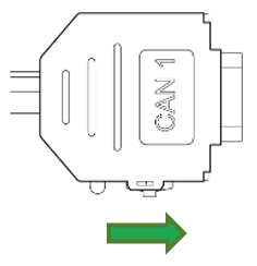 ✅ The LED on the D-Sub connector (CAN1) lights up red.
 -
Wait until both LEDs on the device light up orange.
✅ The device is now in the "Repair mode ready" status.
Note
To abort the device reset , disconnect the power supply while the LEDs are still orange and Slide the switch on the D-Sub connector (CAN1) toward the LED while the device is powered off.
-
Slide the switch on the D-Sub connector (CAN1) toward the LED.
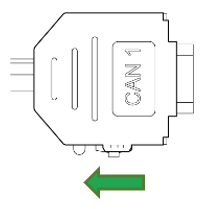
Figure 1: Switch to exit Reset Mode ✅ Both LEDs light up green for a second and change to LED ON = steady green and STATUS = green blinking.
Note
✅ After the reset to factory settings, all wireless interfaces are disabled.
✅ The CAN bit rate is 250 kbit/s.
Note
For further information on the LED status signals, see chapter Indicator Element (LED).
Factory Reset Device via Object Dictionary
Another method of performing a factory reset is by using the Object Dictionary.
If the value 0x64616F6C is written to object 0x1011:0x01 [Restore all default parameters], the device immediately performs a factory reset.
While the factory reset functionality is available to customers, it should be used cautiously and preferably by trained personnel who understand the implications.
As noted, any configurations will be lost unless previously saved with the Proemion Configurator.
It's advisable for customers to consult with Proemion support or refer to device-specific documentation before performing a factory reset.
Factory Reset Device via Proemion Configurator
The device can be simply reset to the Factory default settings using the Proemion Configurator.
- Connect to the device
- Select Tools > Reset device to factory settings...
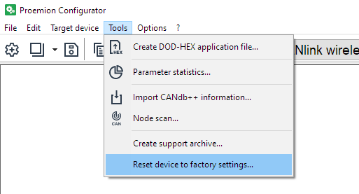
There is no feedback.
The device will simply be initialized to how it was delivered from the factory.
Cyber-security
Cybersecurity involves protecting data and behavior from cyber threats such as hacking, phishing, and malware.
It ensures that sensitive information remain secure while using digital services.
Carefully considering cybersecurity is crucial because it helps prevent data and or financial loss, and ensures safe and reliable operation of connected systems.
Various tips to increase security are discussed.
Info
The default ('factory') configuration of the CANlink® wireless 4000 has all wireless interfaces disabled:
- Wi-Fi
- Bluetooth
- BLE
This means that unless specifically altered, the device is impervious to unwanted connections and interference.
In order to connect to the device and enable any wireless interface, a connection over the CAN bus must be established.
See Connect over CAN bus.
Wi-Fi Password
Access Point
When configured as a Wi-Fi Access Point (AP), the CANlink® wireless 4000 allows connections from one or more Wi-Fi Clients.
(More than one connection to a Client requires Multipoint/MultiTalk).
In order to prevent an insecure network, the AP must be configured:
- with WPA2 enabled, and
- with a 'complex' password
The password requirements mandate all of the following:
- length between 24 and 63 characters
- at least 1 lower case
- at least 1 upper case
- at least 1 numerical (0 - 9)
- 1 special character (
!#&, etc)
Tip
If the AP does not accept Client connections, check 0x3001:0x0C [Error Code/ WiFi - Bluetooth].
- If the password is not valid when creating the AP, the error code
0xDEADC0D1will be present. - If the AP was started with Open Authentication selected, the error code
0xDEADC0DEwill be present.
Client Configuration
When configured as a Client, any form of connection may be made:
0: Open authentication (None)7: WPA/WPA2 Mixed with whatever password is configured on the Server.
Bluetooth PIN
Warning
For security reasons, do not disable the PIN on the Server device.
If disabled, any BT Client will be able to connect!
Disabling the PIN might be acceptable only when other measures ensure that no unauthorized personnel or device can come within connection-distance from the Server device.
For example, when the Server device is located in an area with physical restrictions.
BLE Security
The BLE interface 0x3008:0x09 [BLE Enable] is disabled by default.
Additionally, the BLE WhiteList 0x3009:0x0B [BLE Whitelist - Enable] is enabled by default.
Warning
Disabling the BLE whitelist removes access control for incoming BLE connections.
When the whitelist is disabled using 0x3009:0x0B [BLE Whitelist - Enable], any BLE central device can establish a connection.
Disable the whitelist only if other measures ensure that unauthorized devices cannot reach the BLE connection range.
This may be acceptable in environments with physical access restrictions, such as controlled or enclosed areas.
See BLE WhiteList for more details about BLE security.
Hide Wi-Fi SSID broadcast
The CANlink® wireless 4000, if defined as a Wi-Fi Access Point (AP), can disable the broadcast of the network SSID. Clients can still connect to this AP, but they must know the SSID beforehand.
Also, when configured as a Client device, it is possible to connect to an AP with a hidden SSID (if that SSID is known).
Warning
Hiding the Wi-Fi SSID is a poor form of security, known as "Security through obscurity".
There are tools freely available that can find hidden SSIDs.
Hiding the SSID can reduce the ease of connection by a naïve user, but a determined user will be able to connect even when the SSID is 'hidden'.
Server Configuration
The device must be initially configured as a Wi-Fi® Server.
-
Set
0x30000x1F [WiFi Hide SSID broadcast]to1 (Enabled). -
Hidden SSID is only possible within a secure network, therefore, set
0x3000:0x04 [WiFi Authentication Type]to7 [WPA/WPA2 Mixed]to enable it. -
As discussed in Wi-Fi Encryption, the
0x3000:0x05 [WiFi Authentication Key]must be configured.
The SSID will be hidden upon next boot of the device, and will remain hidden until either being disabled, or a Factory Reset is performed, see also Reset Device.
Client Configuration
No specific client configuration is needed in order to connect to an Access Point (AP) with a hidden SSID.
As long as:
- the authentication
0x3000:0x04 [WiFi Authentication Type]is set to7 [WPA/WPA2 Mixed], and - the correct SSID is in
0x3010:0x1A [Bluetooth SPP MAC Address 1], and - the password in
0x3000:0x05 [WiFi Authentication Key]matches the Server password
the the Client will connect to the hidden Wi-Fi® SSID.
Q & A
Q: Currently, Wi-Fi WPA/WPA2 mixed is in use. Is the transition to WPA3 being considered?
Not at this time.
Q: Can MAC address filtering be implemented to allow only one device connection at a time?
- For Bluetooth connections, yes. The MAC address of the Server can be selected in the Client, and only that device will be connected to.
- For Wi-Fi connections, not at this time.
Q: Filtering Mechanism: There is a CAN filtering mechanism available for CAN to wireless communication to reduce unnecessary traffic. Similarly, is CAN filtering from the wireless interface to the CAN bus supported?
No - all messages sent via wireless connection to the CLW4000 are forwarded to the CAN bus.
This direction should already contain relevant data only to reduce bandwidth.
Q: Locking Device Configuration: Can device configuration settings be locked from access by a wireless connection, or the CAN bus?
No, almost all CANlink® wireless 4000 settings are available for modification using CANopen by a connected peer.
Everything connected is considered trusted.
Q: Intrusion Detection: Is an intrusion detection system (IDS) implemented to monitor unauthorized access?
No. Everything already connected is considered trusted.
Troubleshoot and Maintenance
Troubleshooting and maintenance
This chapter contains advice on eliminating possible errors and notes on maintenance.
Troubleshooting
| Problem | Advice |
|---|---|
| Device is without any function | Check the power supply via the CAN connector |
| Device does not receive CAN messages | - Check the CAN connection and the configuration of the CAN messages and filters. |
| - Check if the CAN bus termination resistor is correctly installed. | |
| Device is stuck in sleep mode | - Check if terminal 15 is connected or VCC is connected. |
| - Check CAN traffic is present | |
| - Refer to the Power Management section. | |
| Device does not transmit all CAN messages | - Check if the CANopen stack is enabled. |
| - Change the CAN identifiers of the affected CAN messages (Rx SDOs, Tx SDOs, emergency messages). | |
| Device does not transmit any CAN messages | - Check the CAN baud rate |
| - Check the wiring | |
| - Check the CAN bus termination resistors | |
| - Check the CAN message filter settings in the CAN filters section. |
If you do not find the solution to your problem within this manual, contact the Service and Support, The support team requires the following information in order to help you.
-
Description of the problem.
-
Serial number of the device.
-
Firmware version of the device.
-
Support archive. See chapter Create Support Archive.
-
What is the LED status?
Maintenance
-
Regularly check all connectors for a firm connection.
-
Regularly check the housing for cracks or any other damages.
Cleaning
Note
Risk of property damage
Damage to the device due to water penetration:
-
The device was tested against water jets according to IPxK6 of ISO 20653 standard. Different loads, e.g., with a pressure washer or a higher flow rate, do not correspond to the intended use.
-
Never clean the CANlink® wireless 4000 device with a pressure washer or similar.
To avoid damage caused by liquid ingress, no high-pressure cleaners may be used for cleaning. In order to remove contamination, you should also avoid using jet water if possible. Instead, use a damp cleaning cloth with a solvent-free and acid-free cleaning liquid.
Make sure the device is mounted as recommended to avoid liquid ingress, see Mounting Orientation.
Remote Bluetooth Address
The "Remote Bluetooth Address" object is used to add a "Bluetooth MAC Address" in order to make the device connect to a remote device.
In order to remove a connection to the previous remote device, use the "disconnect" command.
it is not required to delete the MAC address in order to make the device not connect to the configured address. But in order to delete the MAC address that was configured before, you must write an empty string (\0) to the CANopen object.
Packaging and Transport
This chapter contains information on packing and transportation.
Note
Risk of property damage.
Only store and transport the device in a temperature range of
- -40°C - 80°C
- -40°F - 176°F
Disposal
This chapter contains information on correct disposal.
Note
Observe local regulations for disposal of the device, the accessories and the packaging material.
Regulations in the European Union
 According to the Directive on Waste Electrical and Electronic Equipment (WEEE), the device must not be disposed of in household waste.
Take the device to a collection point for waste electrical and electronic equipment for correct disposal.
Annex
This chapter contains technical data and certificates.
Technical Drawings
Note
You can download the CAD files from our Download Center under: 03_Proemion Tools Software > 01_Software.
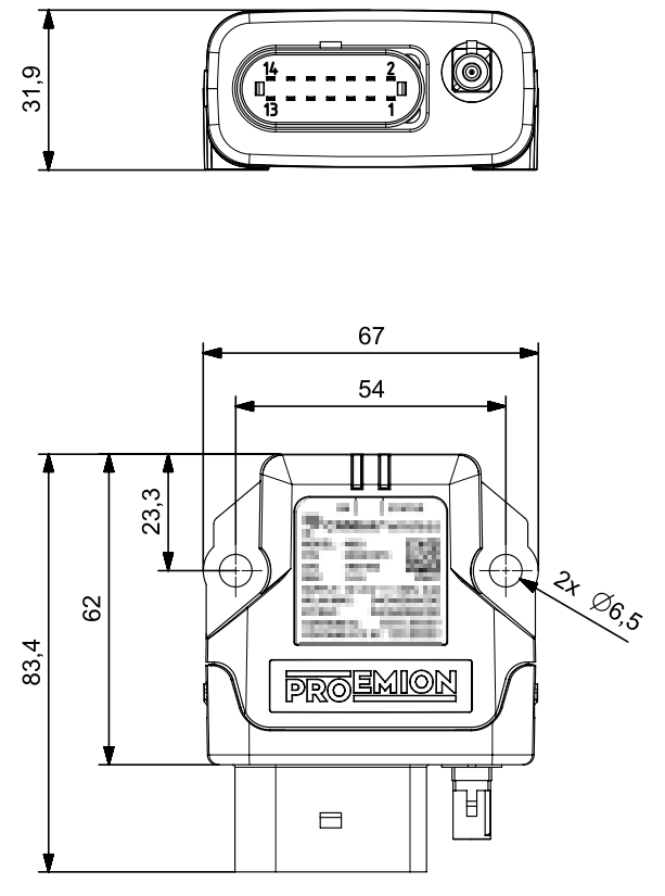
Note
The dimension for the CANlink wireless 4001 are equal to the dimensions of the CANlink wireless 4003. The only difference is the external FAKRA connector at the CANlink wireless 4003.
Technical Data
This chapter contains information on the technical data of the device.
Mechanical
Electrical
| Parameter | Value |
|---|---|
| Supply voltage range terminal 30 | Rated voltage 12V / 24V Tolerance ±50% (range 6V to 36V) |
| Power consumption, at 24 V (Operating Ø) | < 100 mA |
| Power consumption in sleep mode | < 1 mA |
| Average power consumption | < 2 W |
| Processor | ARM® Cortex M7 based STM32 (400 MHz) |
| Memory expansion Program Flash | 1 MB |
| Data Flash memory expansion | 16 MB |
| Memory expansion FRAM | 8 kB |
| Memory expansion SRAM | 564 kB |
| LEDs | 2 LEDs (RGB) |
Interfaces
Note
Please be aware that the measured performance values were determined in the free field without significant interference or signal dampening.
The maximum range, latency and the possible message throughput may vary considerably depending on the environmental influences, setup condition, the used antennas and, if applicable, the hardware installed for the Wi-Fi infrastructure.
Please consider these values just as approximate reference values which can be achieved in a specific test setup under ideal conditions.
It is the system integrators responsibility to verify the connection stability and performance under real ambient conditions as part of the final application and setup.
When designing the application and programming the control unit, it is important to ensure that certain latency times and connection interruptions are tolerated by the control and treated accordingly.
An end-to-end monitoring of the message transmission is recommended in any case.
Please note that the quality of the radio connection depends largely on external influences and cannot be guaranteed at any time.
It is therefore essential to provide appropriate error handling in the application for any delays or connection interruptions.
| Parameter | Value |
|---|---|
| CAN interfaces | 2 (no galvanic isolation) |
| CAN specification | - CAN - CANopen (ISO 11898-22016, SAE J2284-1, SAE J2284-5) |
| Maximum CAN baud rate | 1 Mbit/s (CAN, CANopen) |
| Digital OUT | 1 digital output - Terminal 30 switching 6 VDC - 36 VDC - max. output current 500 mA - max. switch frequency 10 Hz - Overvoltage protection up to 36 VDC - Reverse voltage protection up to -36 VDC - incl. diagnostic and analog read back of output voltage The digital output visualizes an active (Wi-Fi TCP/SPP/BLE) connection, if the respective TCP/SPP/BLE interface is enabled and the Digital Output option is enabled. The option can be enabled by writing value 1 to the object in 0x3333:0x6E, 0x6F or 0x70. See also Digital Output |
| Analog IN | 2 analog inputs - Measurement range 0 VDC to 15 VDC - Input resistance 20 kOhm - Resolution 12 bit - Sampling rate 20 Hz - Overvoltage protection up to 36 VDC - Reverse voltage protection up to -36 VDC - Tolerance ± 1 % of measurement range end value (at 25 °C) |
| Terminal 15 | Analog input - Measurement range 0 VDC to 36 VDC - Input resistance 20 kOhm - Resolution 12 bit - Sampling rate 20 Hz - Overvoltage protection up to 36 VDC - Reverse voltage protection up to -36 VDC - Tolerance ± 1 % of measurement range end value (at 25 °C) - Low-to-High Transition Wakes up the device from SleepMode |
| Operating modes | - Bridge Mode Device connection to (up to seven) device(s) - Gateway Mode Device connection to third-party device, such as a laptop or mobile phone or service device Both modes can be achieved with a Wi-Fi, Bluetooth or BLE connection |
| Bluetooth Standard | Bluetooth classic (2.1 EDR) |
| Bluetooth Low Energy | V5.0 with long range support (Bluetooth LE) |
| Wi-Fi Standard | - IEEE 802.11a/g - IEEE 802.11b - IEEE 802.11n |
| Wi-Fi encryption | - WPA/WPA2 Mixed |
| Wi-Fi transmission rate | - IEEE 802.11a to 54 Mbit/s - IEEE 802.11b to 11 Mbit/s - IEEE 802.11g to 54 Mbit/s - IEEE 802.11n to 65 Mbit/s |
| Data transfer rate CAN messages per second that can be transmitted without data loss Tested with Baud rate 1 Mbit/s |
- Bluetooth Single point 2,000 CAN messages per second (Server to Client) - Wi-Fi Access Point, Single Point 4,000 CAN messages per second - Wi-Fi Infrastructure mode Single Point 4,000 CAN messages per second - BLE, Single point 500 CAN messages per second (Server to Client) |
| Average latency period for transmission of a single CAN message Tested with Baud rate 1 Mbit/s |
- Bluetooth Bridge Single Point 23 ms - Wi-Fi® Bridge Single Point 9 ms |
| Range | Each wireless interface is tested to verify full performance over a range of 100m Longer range may be expected under certain environmental conditions, and local weather and choice of aerial can affect range. |
| Antenna Connector | - 4001 internal antenna - 4003 FAKRA connector (male), code I IMPORTANT: to avoid losing the radio approval of the Wi-Fi module, only use approved antennas |
| Buffer sizes | - Wireless receive buffer 525 messages- CAN receive buffer 275 messages |
Protocols
| Protocol | Available |
|---|---|
| Layer 2 | Yes |
| CANopen | Yes |
| Customer-specific | On request |
| TCP | Yes |
| Serial Port Profile (SPP) | Yes |
| RM Byte Command Protocol | Yes |
Status Indicators
| Variant | Status indicator |
|---|---|
| 4001 | 2 RGB LED |
| 4003 | 2 RGB LED |
Certification and Qualification
The device has been certified and qualified according to the valid standards and regulations.
For more information on the corresponding approval tests, please contact the Proemion support.
Note
We will send you an overview of national approvals on request.
Please contact our support. See chapter Service and Support.
Hereby, Proemion GmbH declares that the radio equipment type CANlink® wireless 4000 is in compliance with Directive 2014/53/EU.
The full text of the EU declaration of conformity is available at the following internet address Declaration of Conformity.
Note
Further certificates, such as FCC, are also available at our website Declaration of Conformity.
Note
Further listing details of the Bluetooth SIG standard can be found at the Bluetooth Declaration Details.
E1
ECE Regulation No. 10 (Revision 6)
Approval number 10R-06 9612
Abbreviations
| Abbreviation | Origin | Notes |
|---|---|---|
| CTO | Custom Transmit Object | Proemion's proprietary implementation of PDO configuration. Requires Proemion Configurator |
| DOD | Device Object Dictionary | Proemion's proprietary format for specifying the objects and data to configure a CANlink device with the Proemion Configurator |
| PAN | Personal Area Network | A (Bluetooth Classic) ad-hoc wireless connection that allows the devices to communicate directly with each other. |
| PDO | Process data objects | Used in CANopen for broadcasting high-priority control and status information, consisting of a single CAN frame and up to 8 bytes of pure application data |
| TPDO | Transmit PDO | Transmission from the Proemion device |
Service and Support
The latest versions of the drivers, software, firmware, and documentation are available at Document Library.
Do you need help or want to report a bug?
Visit Proemion for more information, or raise a ticket via Support.
Firmware Updates and Support
To ensure the best performance and security of your devices, we strongly recommend always installing the latest firmware provided by Proemion.
Please note:
We do not provide technical support for issues caused by outdated firmware.
Errors resulting from outdated firmware are considered non-qualified errors and are not covered by warranty or support.
Regular firmware updates are essential to maintaining the functionality of your devices.
If you need assistance with the update process, please contact our Service and Support.
For more information on the Firmware Update, check the device manual of your device at the Document Library.