Digital Output
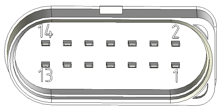
It is possible to use the pin 7 digital output of the Main Plug Connector interface of the CANlink® wireless 4000.
There are two ways that this output can be used:
- Manual
- Wireless Connection Active
Manual Output
In this mode, the output can be switched manually by setting the value of an object in the Object Dictionary.
Set 0x3333:0x0F [Digital Output] to 0 to output a low voltage, and 1 to output high.
This value is volatile, so it must be configured by an external controller after each reboot.
Wireless Connection Active
This mode represents the state of a wireless connection by setting the pin 7 output appropriately: High when connected, and Low when not connected.
This value can represent one of each of the three wireless interfaces: WiFi, Bluetooth and BLE:
- For WiFi, set
0x3333:0x6F [Digital Output Connection Visualization Wifi]to0x01. - For Bluetooth, set
0x3333:0x6E [Digital Output Connection Visualization Bluetooth SPP]to0x01. - For BLE, set
0x3333:0x70 [Digital Output Connection Visualization BLE]to0x01.
In all cases, set the unwanted interface objects to 0x00 (disabled).
Output Physical Properties
Pin 7 switches the voltage applied to Pin 1 (Terminal 30, Vcc):
- The maximum output current is 500mA
- Maximum switching frequency is 10Hz
Switched by another device
An example of the Digital Output being switched by another device sending a CTO is contained in the CTO Walkthrough.