Indicator Element (LED)
The front of the device features two RGB LEDs for indicating function and status.
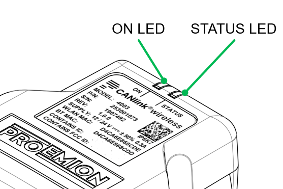
The following table shows possible ON LED states:
| ON Color | Indication | Meaning |
|---|---|---|
| - | Off | Device is switched off or in sleep mode. For more information, read Power Management. |
| Green | Slow Blinking | Device is in update mode and ready to receive an application firmware. The STATUS LED is blinking in parallel. |
| Green | Fast Blinking | Firmware flashing process. The STATUS LED is blinking in parallel. |
| Green | On | Device is switched on, terminal 30 voltage in permitted range (>= 6 and < 36 V). |
| Red | On | Device is switched on, terminal 30 voltage outside permitted range (< 6 or >= 36 V). |
| Orange | On | Device is in device reset mode (STATUS LED is also orange in parallel). |
The following table shows possible STATUS LED states:
| STATUS Color | Indication | Meaning |
|---|---|---|
| - | Off | Device is switched off or in sleep mode. For more information, read Power Management. |
| Green | Double Flash (200 ms on, 200 ms off, 200 ms on, 1000 ms off) |
Initialization of the Device. |
| Green | Triple Flash (200 ms on, 200 ms off) |
Device is ready for connection. |
| Green | On | Device is connected to a peer. There is no error. |
| Green | Slow Blinking | Device is in update mode and ready to receive an application firmware. The ON LED is blinking in parallel. |
| Green | Fast Blinking | Firmware flashing process. The ON LED is blinking in parallel. |
| Blue | Blinking | Data transfer active. |
| Blue | On | There is an wireless connection error. |
| Orange | Single Flash | Device received CANopen SDO request |
| Orange | On | CAN1 Error. |
| Red | On | CAN2 Error. |