CTO Demonstration 2
Here, we show how to configure sending a CTO wirelessly, which demonstrates:
- Wi-Fi Automatic Channel Selection
- Switching the Digital Output of another device
- Sampling the device Analog Input
- Sending a PDO on State-Change of the Analog Input
Outcome
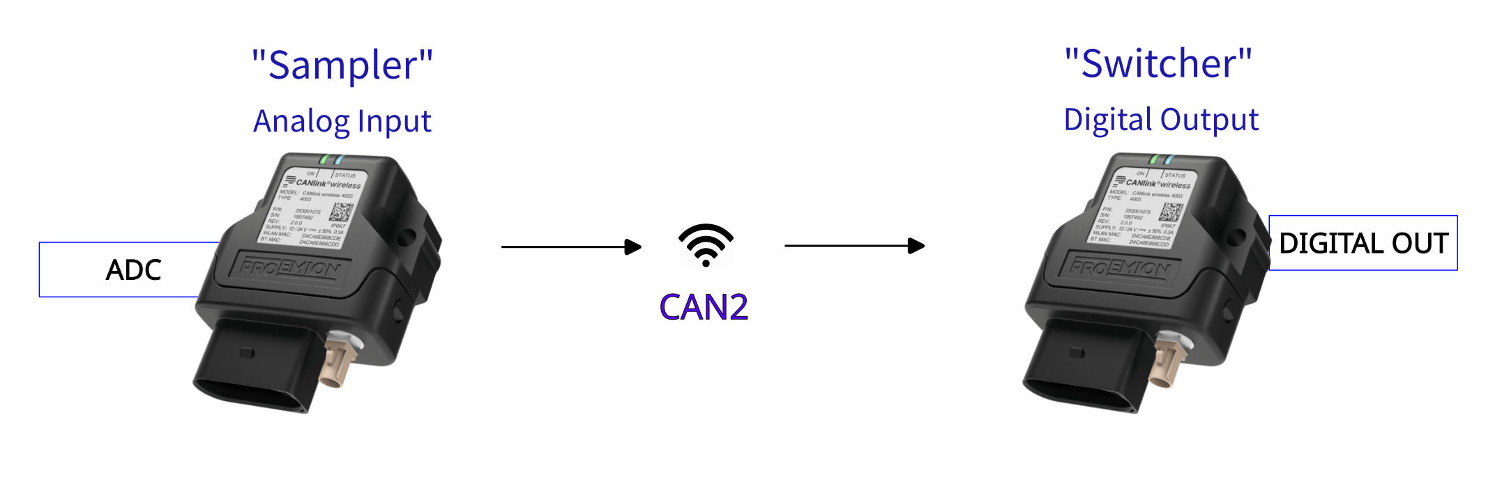
This setup will have once device "Sampler" that reads its analog input, and switches the digital output of the other ("Switcher") device as the detected voltage changes between higher and lower than 12V.
This will be actioned with an SDO 'Expedited Transfer'.
Assumptions
- Supply voltage is 24V.
The output of the "Switcher" should be High when the voltage is greater than 12V on the "Sampler", and otherwise Low. - "Sampler" has Node-ID of 34; "Switcher" has 35.
- The CTO Demonstration 1 walk-through has been understood, as it introduces fundamental CTO concepts.
Basics
- Standard CAN2.0 PDO payload is 8 bytes.
"Sampler" Setup
This is the device that reads its analog input, and sends appropriate CTOs depending on the value.
We want to write one byte into the "Switcher" Object Dictionary, which will switch the Digital Output state.
Calculate the message bytes
Refresher
SDO Message Structure
| Byte | Description |
|---|---|
| 0 | Command byte (contains CCS, expedited flag, size indicator) |
| 1 | Index low byte |
| 2 | Index high byte |
| 3 | Subindex |
| 4–7 | Data (up to 4 bytes, depending on flags) |
Command Byte Breakdown
This byte encodes the Client Command Specifier (CCS) and control flags:
- Bits 7–5: CCS (3 bits)
- Bit 4: Reserved
- Bits 2–3: Number of unused bytes in data field
- Bit 1: Expedited transfer (1 = yes)
- Bit 0: Size indicated (1 = yes)
CCS values
| Value | Meaning |
|---|---|
| 1 | Initiate download request |
| 2 | Initiate upload request |
| 3 | Upload response |
| 4 | Download response |
| 5 | Abort transfer |
So the final Command Byte can be calculated of:
Command Byte summary
| Value | Meaning |
|---|---|
| 0x20 | CCS = 1 (Initiate download request) |
| 0x0C | Three unused bytes |
| 0x02 | Expedited transfer |
| 0x01 | Size Indicated |
| 0x2F | Final value |
(Assume that we want to turn on the Digital Output for this initial calculation).
-
Set the COB-ID to send to Node-ID 35 (decimal).
SDO Rx =0x600+ Node-ID
With the "Switcher" Node-ID of 35 (decimal), we set the COB-ID to0x623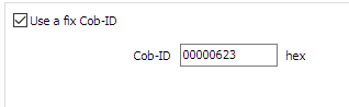
Figure 2: Set COB-ID -
The Command specifier as calculated above for 'SDO Expedited Download (write 1 byte)' is
0x2F.
This is the first byte in the message data. -
The Index and Sub-Index for the Digital Output is
0x3333:0x0F. -
To enable the Digital Output, we write a
1.
Putting these together, the bytes to transmit are:
| Value | Byte number | Meaning |
|---|---|---|
0x2F |
Byte 0 | Command specifier Expedited Download (write 1 byte) |
0x3333 |
Byte 1 - 2 | Index |
0x0F |
Byte 3 | Sub-Index |
0x01 |
Byte 4 | Data to write (Enable) |
The CANlink® wireless 4000 does not have an Operations Manager as the CANlink® mobile 3600 does, so we must store these values in the Object Dictionary to be sent out in this PDO message.
There are five bytes to send, which could be two 32bit values, and one more byte.
We can simply pick any unused objects in the Object Dictionary, write the desired values into them, and then send these objects with this message is triggered.
In this example, we will use the following objects:
0x3330:0x10 [Trimble X coordinate CAN ID]0x3330:0x11 [Trimble Y coordinate CAN ID]0x3330:0x12 [Trimble Z coordinate CAN ID]
Each are 32bit objects.
One PDO message sends eight bytes, so there will be two of these objects per message.
The messages are identical, apart from Byte 4, which changes between 1 for output High, and 0 for output Low.
Therefore we can use the same first object in both messages, and just change the last object depending on the desired state of the Digital Output in the "Switcher" device.
(We could use any other one byte object for the 'enable/disable' Byte 4 - but for consistency, we chose this for this example).
Add objects for CTO
In order for the logic to function, some Objects must be added to the Configuration as Device Variables.
For clarity, add them to a folder called CTOs.
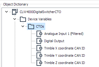
0x3340:0x01 [Analogue Input 1 (Filtered)]for measuring the voltage0x3333:0x0F [Digital Output]. This is the object on "Switcher" we request to change.0x3330:0x10 [Trimble X coordinate CAN ID]. Used for the first four bytes of the message.0x3330:0x11 [Trimble Y coordinate CAN ID]. Used for 'Enable'.0x3330:0x12 [Trimble Z coordinate CAN ID]. Used for 'Disable'.
Configure objects for CTO
In this diagram we show the bytes required in the message to enable the Digital Output in the "Switcher" device (Byte 4 is 0x01).
The bytes are transmitted in Little-Endian format, and the values are shown in the configuration as Big-Endian.
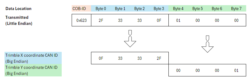
To transmit the bytes in the correct order, the 32 bit objects must be flipped to Little-Endian ordering.
The result is shown at the bottom of this diagram, which is what the values of those objects should be:
- Set
0x3330:0x10 [Trimble X coordinate CAN ID]to0x0F33332F - Set
0x3330:0x11 [Trimble Y coordinate CAN ID]to0x00000001 - Set
0x3330:0x12 [Trimble Z coordinate CAN ID]to0x00000000
(Writing0x00turns the Digital Output to Low).
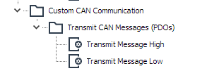
Add PDOs
Now we can set up the PDOs — one for a High Digital Output, and one for Low.
-
Add two Transmit Message PDOs by right-clicking on 'Custom CAN Communication'.
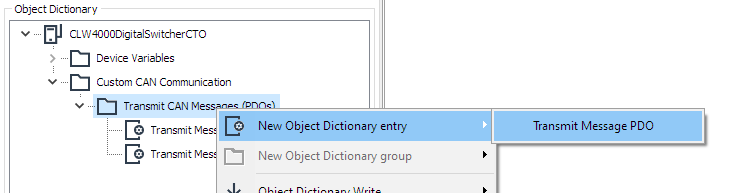
Figure 6: Add new PDO -
Name appropriately.
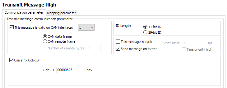
Configure Message High PDO
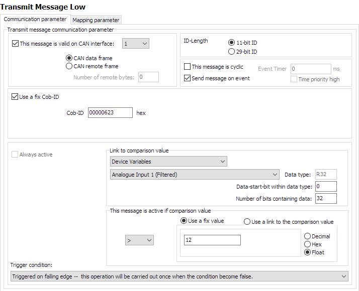
First, configure the 'Communication parameter' tab:
- Enable output on CAN 1.
- Set ID-Length to 11-bit ID.
- This event will be sent on an event (voltage rising or falling past 12V).
- Use a fix COB-ID
0x623.
The settings will look like the following:
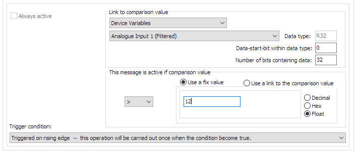
Next, the trigger condition:
-
The comparison value will be the
Analogue Input 1 (Filtered)on this device.
Select that object from the Device Variables that we have included in this configuration. -
Select a comparison to a fixed value (voltage) of
12.
If the value rises about this, the message should be sent. -
Ensure the comparison logic is 'greater than'
>. -
The trigger is set to 'rising edge' — the PDO is sent when the condition (voltage > 12) is true.
The final condition will look like the following:
Next, the Mapping Parameter:
-
Select the 'Mapping parameter' tab.
-
Select the first bytes to form the final message (
Trimble X coordinate CAN ID)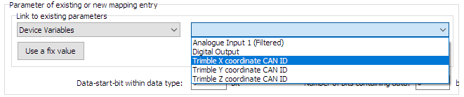
Figure 9: Select first bytes -
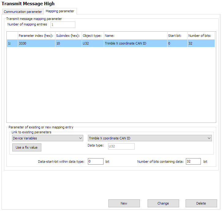
We want all 32 bits to be in this message, so the 'Data-start-bit within data type' stays as zero.
'Number of bits containing data' is 32 (all bytes in the object). -
Click 'New' to add.
The first parameter has been added, and will look like the following:
Next, add the remaining data bytes:
- Just as before, add
Trimble Y coordinate CAN IDto form the remaining four bytes.
The final 'Mapping Parameter' for the 'Transmit Message High PDO' are now:
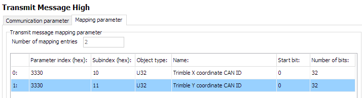
This PDO is now complete.
Configure Message Low
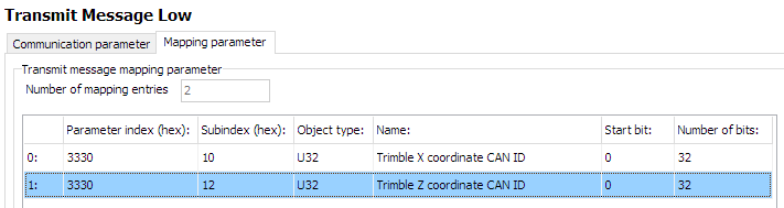
In a very similar way, we construct the 'Transmit Message Low' PDO.
The only difference is that we trigger on voltage falling below 12V, and send the Trimble Z coordinate CAN ID with value 0x00000000 to turn the Digital Output to Low.
This changes the value written to the Digital Output object to 0 — Low.
We can simply check for a false condition on the same comparison for this PDO:
The mapping is essentially the same, but substituting Trimble Z coordinate CAN ID for Trimble Y coordinate CAN ID:
The CTO configuration is finished.
Now just set the device to connect to the "Switcher" device.
Network setup
We will connect to the "Switcher" device on 2.4GHz Wi-Fi band.
The following objects are required.
| Object | Setting |
|---|---|
0x3000:0x01 [Wi-Fi Operating Mode] |
0x01 [Infrastructure] |
0x3000:0x10 [Enable 2.4GHz WiFi Band / Infrastructure only] |
1 Enabled |
0x3000:0x11 [Enable 5GHz WiFi Band / Infrastructure only] |
0 Disabled |
0x3008:0x03 [Bluetooth Enable] |
0 Disabled |
0x3008:0x09 [BLE Enable] |
0 Disabled |
0x3008:0x02 [WiFi Enable] |
1 Enabled |
0x3000:0x04 [WiFi Authentication Type] |
7 [WPA/WPA2 Mixed] |
0x3000:0x09 [WiFi DHCP Mode] |
1 [DHCP Client (WiFi infrastructure only)] |
0x3000:0x25 [WiFi Region] |
As Appropriate |
0x3000:0x02 [WiFi SSID] |
PDO_Server |
0x3000:0x05 [WiFi Authentication Key] |
ChocolateCake4Breakfast! |
0x3010:0x15 [Connection Direction Configuration/Server or Client 1] |
3 [Client enabled] |
0x3010:0x16 [Connect Type 1] |
1 [TCP Socket] |
0x3010:0x17 [URL Address/WiFi Client only 1] |
192.168.0.35 |
0x3010:0x18 [Socket Listen Port/WiFi only 1] |
30000 |
0x4050:0x03 [Node Id CAN 1] |
34 |
"Switcher" Setup
This is the device that receives CTOs from the "Sampler", and switches its digital output appropriately.
The Node-ID is 35 decimal. "Sampler" has a Node-ID of 34 decimal.
Network setup
In contrast to the "Sampler" configuration - the "Switcher" is just a Wi-Fi Server (Access Point).
There is no configuration required related to PDOs — no effort is required to receive a PDO.
Consequently, only a typical Wi-Fi Server configuration is required:
| Object | Setting | Notes |
|---|---|---|
0x3000:0x01 [Wi-Fi Operating Mode] |
0x02 [Mini Access Point] |
|
0x3000:0x10 [Enable 2.4GHz WiFi Band / Infrastructure only] |
1 Enabled |
|
0x3000:0x11 [Enable 5GHz WiFi Band / Infrastructure only] |
0 Disabled |
|
0x3008:0x03 [Bluetooth Enable] |
0 Disabled |
|
0x3008:0x09 [BLE Enable] |
0 Disabled |
|
0x3008:0x02 [WiFi Enable] |
1 Enabled |
|
0x3000:0x04 [WiFi Authentication Type] |
7 [WPA/WPA2 Mixed] |
|
0x3000:0x09 [WiFi DHCP Mode] |
2 [Server (WiFi MiniAP only)] |
|
0x3000:0x25 [WiFi Region] |
As Appropriate | |
0x3000:0x02 [WiFi SSID] |
PDO_Server | |
0x3000:0x05 [WiFi Authentication Key] |
ChocolateCake4Breakfast! | |
0x3000:0x0F [Access Point WiFi Channel / MiniAP only] |
0 |
Automatic Channel Selection |
0x3010:0x15 [Connection Direction Configuration/Server or Client 1] |
2 [Server enabled] |
|
0x3010:0x16 [Connect Type 1] |
1 [TCP Socket] |
|
0x3010:0x17 [URL Address/WiFi Client only 1] |
192.168.0.35 |
|
0x3010:0x18 [Socket Listen Port/WiFi only 1] |
30000 |
|
0x4000:0x16 [CAN Message Output CAN2] |
1 [Start Msg. Output active] |
|
0x4050:0x03 [Node Id CAN 1] |
35 |
After boot, this device will wait for a connection request on port 30000, and accept one Client.
If the voltage fluctuates around the 12V value, a PDO will be received that write to the 0x3333:0x0F [Digital Output] object.
The output will be High if a 1 is written, and Low if 0 is written.