CAN Functions
This chapter provides information on how to use and configure CAN functions.
CAN / CANopen
Note
You can find the CANopen objects documentation for configuring and operating the CANlink® wireless 4000 via CANopen in the Download Center under: 01_Proemion_Devices > 08_CANlink wireless 4000 > 01_Documentation.
There is an Electronic Data Sheet file (CANlink_wireless_4000_0.eds) and an HTML representation (CANlink_wireless_4000_0.html) provided.
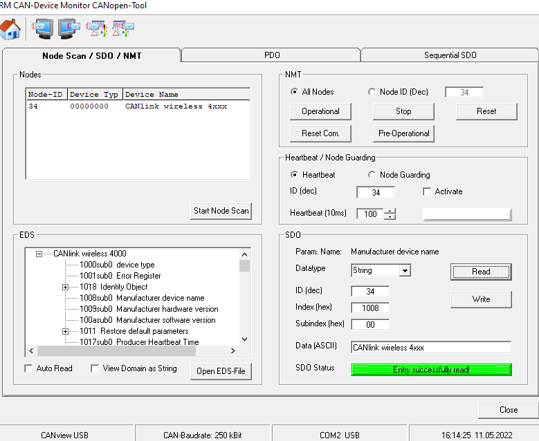
The CANlink® wireless 4000 supports the transmission of pure CAN messages to another device. No direct protocol interpretation is configured in the firmware. This makes it possible to use the device for different applications with various CAN transport protocols. The protocol logic must be implemented in the other device (e.g. in the PC software). An example is the implementation within the CANopen section of the RM CAN Device Monitor Pro CANopen software.
Enabling the CANopen Stack
The CANopen stack prevents the transmission of some CAN messages such as CANopen RX SDOs, TX SDOs, and emergency messages.
These messages are received by the device's CANopen stack and processed to the radio Interface without being forwarded on. It is possible to configure the device for connection control via CANopen.
In that case, the device does not transmit messages with certain CAN identifiers.
The following table shows messages that are used by the device but not transmitted when the CANopen stack is enabled.
| Type | CAN Identifier | Default configuration (Node ID 34) |
|---|---|---|
| TX SDO 1 | 0x580 |
0x5A2 |
| RX SDO 1 | 0x600 |
0x622 |
| Heartbeat/Boot-Up | 0x700 |
0x722 |
| NMT | 0x000 |
0x000 |
Boot-Up message
Directly after startup, the device optionally transmits a CANopen boot-up message with its own node ID.
Note
When this function is enabled, the device expects an acknowledge message from another bus participant.
If no acknowledge message is received, for instance while no other CAN bus participant is active, the LED changes to error mode according to chapter Indicator Element (LED).
CAN1
- To Enable Set bit 0 of
0x4054:0x03to 1 - To Disable Set bit 0 of
0x4054:0x03to 0
CAN2
- To Enable Set bit 0 of
0x4054:0x04to 1 - To Disable Set bit 0 of
0x4054:0x04to 0