Hardware installation
This chapter provides important notes regarding the hardware setup.
Note
Risk of property damage.
- Fasten the cable harness with a suitable strain relief near the CAN / power connector to avoid the transmission of any tension, strains, or vibrations.
- Ensure that there is minimum bending radius of 8 times the outer diameter of the cable harness
Note
Inadequate radio connection
The radio connection is affected by any obstacles and interference.
- Choose the mounting location so that as few obstructions as possible can influence the radio connection.
- When installing, observe the required minimum distance to other antennas and radio devices.
- Avoid interference with other wireless networks.
- Do not stick additional labels on the device.
Depending on the nature of the material, these stickers can severely impair the signal quality.
(Relevant for CANlink wireless 4001 with internal antenna). - The integrator must not modify the device (i.e. place RF-damping labels on it) or mount the device in such a way, that antenna performance is influenced.
- Implement a control-side end-to-end connection monitoring
It is the full responsibility of the integrator to integrate the device in their application in such a way that adequate antenna performance is achieved, and the regulatory requirements are fulfilled.
Note
Please be aware that the measured performance values from chapter Interfaces were determined in the free field without significant interference or signal dampening.
The maximum range, latency and the possible message throughput may vary considerably depending on the environmental influences, setup condition, the used antennas and, if applicable, the hardware installed for the Wi-Fi infrastructure.
Please consider these values just as approximate reference values which can be achieved in a specific test setup under ideal conditions.
It is the system integrators responsibility to verify the connection stability and performance under real ambient conditions as part of the final application and setup.
Mounting the Device
Below you will find instructions on how to mount the device.
To ensure the housing provides proper fire protection and to achieve the best possible reception of radio signals, make sure you install the device in the correct position.
Consider also the note regarding reduced antenna gain and other information in Connecting an external antenna.
Note
Risk of property damage.
- The device can be mounted with the plugs pointing to the left or right. Mounting with the plugs pointing up is not permitted. Mounting with the plugs pointing down is not recommended due to the risk of water ingress.
- Only mount the device in one of the installation orientations shown in this chapter.
- The device is protected against mechanical impacts according to class IK07 (IEC62262 impact energy 2 joules). To achieve a higher class, you must provide external protection when installing the device
Note
The mounting material is not included in the scope of delivery.
Optionally, you can use the MOUNTING SET M6 HOUSING GH0806 (part number 141000021).
The mounting set contains the following components:
- 2 flat headed screw ISO 14583 M6X30 TX
- 2 M6 self-locking hexagon nuts
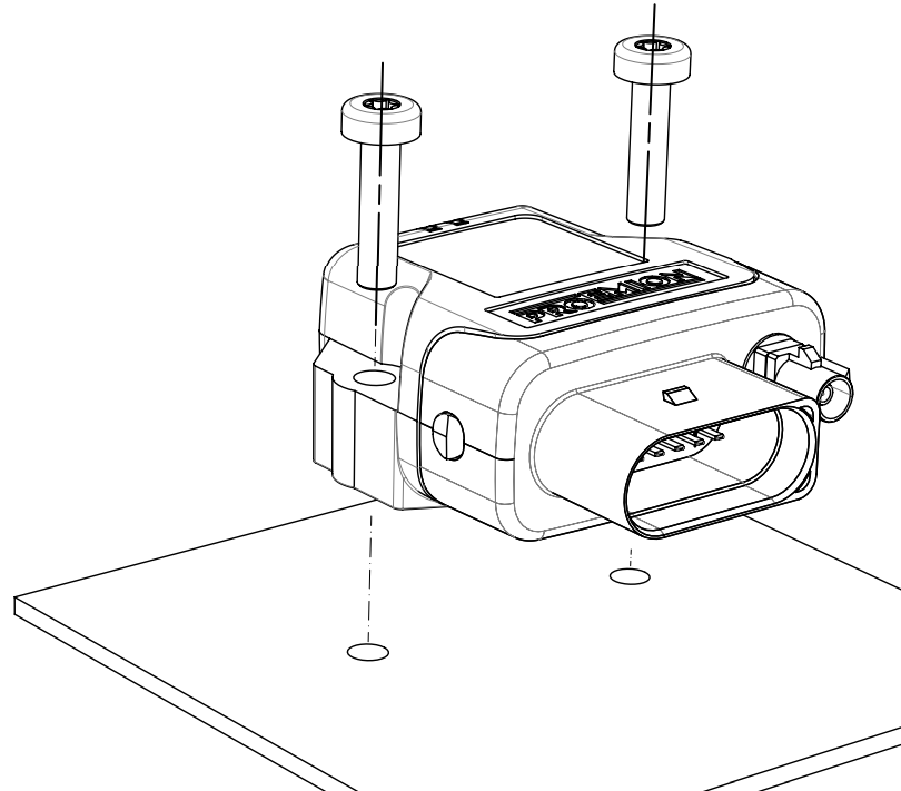
Mounting
Below you will find instructions on how to mount the device.
Directly affix the device with two flat-headed screw ISO 14583 M6X30 TX which are at least 30 mm long.
Tighten the bolts with a torque of 3.4 Nm ±10%.
To secure the bolts, we recommend using two hexagon nuts M6 self-locking.
Note
The mounting material is not included in the scope of supply.
To get the distance of the mounting holes, please refer to chapter Technical Drawings.
Note
The Pressure compensation element at the bottom as shown in Device Elements must not be exposed to direct jet water.
Note
The recommended tightening torque for assembly is 3.4 Nm ±10%.
Note
The outer diameter of the head for the fixing screws must be smaller than 12.5 mm.
Note
For mounting environments that are exposed to the weather or other sources of water, Proemion highly recommends mounting the housing in a way that the gap between the housing and the mounting surface usually has a distance of ≥5 mm to prevent capillary action.
For more information, read the following recommendation.
To mount the device, proceed as follows:
Mount the device with 2 socket-head screws (M5) inserted in the mounting holes on the sides and screwed to the mounting surface (either directly if the device is not exposed to sources of water, or using a mounting plate, see recommendation above).
See Technical Drawings for detailed information on the distances between the holes.
Recommendation for devices exposed to sources of water:
Due to less space between housing and mounting plate, water can reside below the housing because of capillary action.
Especially, the area around the pressure-compensation element needs to be free of water.
Thus, the Mounting Orientation must ensure that no water is being held below this element.
If this cannot be achieved, you must add spacers below the mounting sockets or use a mounting plate that additionally supports the strain relief of the main connector cable.
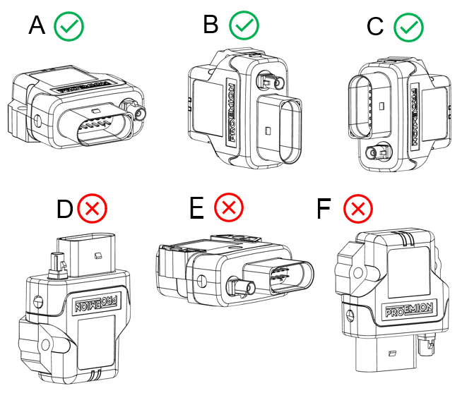
Mounting Orientation
The view elements of the two LEDs on the device do not comply with the flammability class required for a fire protection housing.
Note
Fire protection of the housing is only guaranteed in the installation positions shown in figures A, B or C or F.
Note
Please note that fire protection is not guaranteed in the installation positions shown in figures D and E.
Note
The mounting position F fulfills the requirements of a fire protection enclosure.
But is not recommended due to possible liquid ingress.
Note
To avoid water ingress, please make sure that the mounting orientation of your device is either as shown in figure A, B or C.
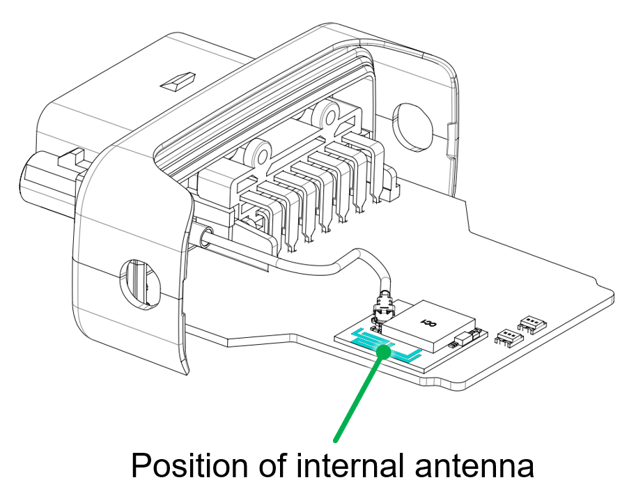
Internal Antenna
The internal antenna of the CANlink wireless variant 4001 is located on the top side of the PCB, therefore, it is recommended to mount the device in such a way that the top side also has the best possible alignment and free sight to its peer.
The 'top ' of the PCB is in the same orientation as the label.
So highest signal connection will be achieved with the two devices facing each other - label to label.
Please refer to figure Antenna positioning.
When using a setup with external antennas, it is also mandatory that the antennas have free sight to each other and are not blocked by any housing materials or other signal dampening materials.
Note
Reduced antenna gain
Problems with the radio connection can be caused by insufficient antenna alignment, interferences, and RF-damping labels.
- Do not stick RF-damping labels onto the housing of the device
External Antenna
Below you will find some important notes regarding the antenna setup.
Note
Inadequate radio connection
The radio connection is affected by any obstacles and interference.
- The antenna cable should be as short as possible to keep signal loss on the cable as low as possible.
- Do not extend the antenna cable. Only use the antennas which are supplied as accessories by Proemion. Bring the radio module closer to the antenna or order an alternative antenna with a longer antenna cable.
- An antenna, particularly outside, should be positioned as high as possible. This allows you to improve the range. This keeps the Fresnel zone clear - the higher, the better.
- Always protect connections on the outside cables, junctions, and antennas with protective tape.
- The external antenna is not to be used as lightning arrester. Select the position of the antenna carefully, use surge protector and do not route the antenna cable parallel to a lightning arrester.
- In the case of insufficient stability of the mounting, the quality of your antenna alignment can be reduced. When mounting the antenna, also think about wind and other outside influences such as ice and snow.
- Install the antenna in an open area, as far away as possible from any obstacles such as buildings, trees, other antennas, or metal objects.
- In case that there is a second antenna installed, calculate the minimum distance. The horizontal distance between antennas should be greater than 1/4 of its wavelength (absolute minimum separation), but it should not be located at the exact multiples of its wavelength (maybe avoid the first 3-4 multiples).
- Establish a sufficient ground connection to the pole, the device, the antenna and surge protection.
- In case of using the antenna supplied in the hardware kit, ensure that the minimum bending radius of the antenna cables is 8 times the outer diameter.