Accessories
The software can be downloaded from our Download Center under: 03_Proemion Tools Software > 01_Software
| Material | SAP Part Number / Ordering code |
|---|---|
| CLW4K Starter Cable 6open 2dsub 1pw 2m | 136000197 |
| Cable MTII 14pin code1 open 2m | 136000198 |
| ADAPTERKABEL CANLINK 14P-M12 5P 30cm This supports the replacement of a CANlink® wireless 3000 by CANlink® wireless 4000 hardware. |
136200001 |
| CANlink Connector Kit Refer to Connector Kit Datasheet for further information |
132600031 |
| ERGOCRIMP HAND TOOL 539635-1 without die-set. This is the Hand Tool required for assembling the Connector Kit |
Direct order at supplier |
| ERGOCRIMP DIE SET for MICRO Timer and Micro Timer (SWS) 539663-2 Micro Timer | Direct order at supplier |
| Mounting Kit M6 Enclosure GH0806 | 141000021 |
| ANT WLDB DA 2M0 FAKRA-I FA | 157000126 |
| Power supply US EU UK AU 24V/0.83A/20W | 257004007 |
| CAN bus terminator D-Sub/D-Sub CANterm 120 | 157000033 |
| PCAN-USB - CAN/USB Interface | 257001041 |
| Launch Kit | 253000187 |
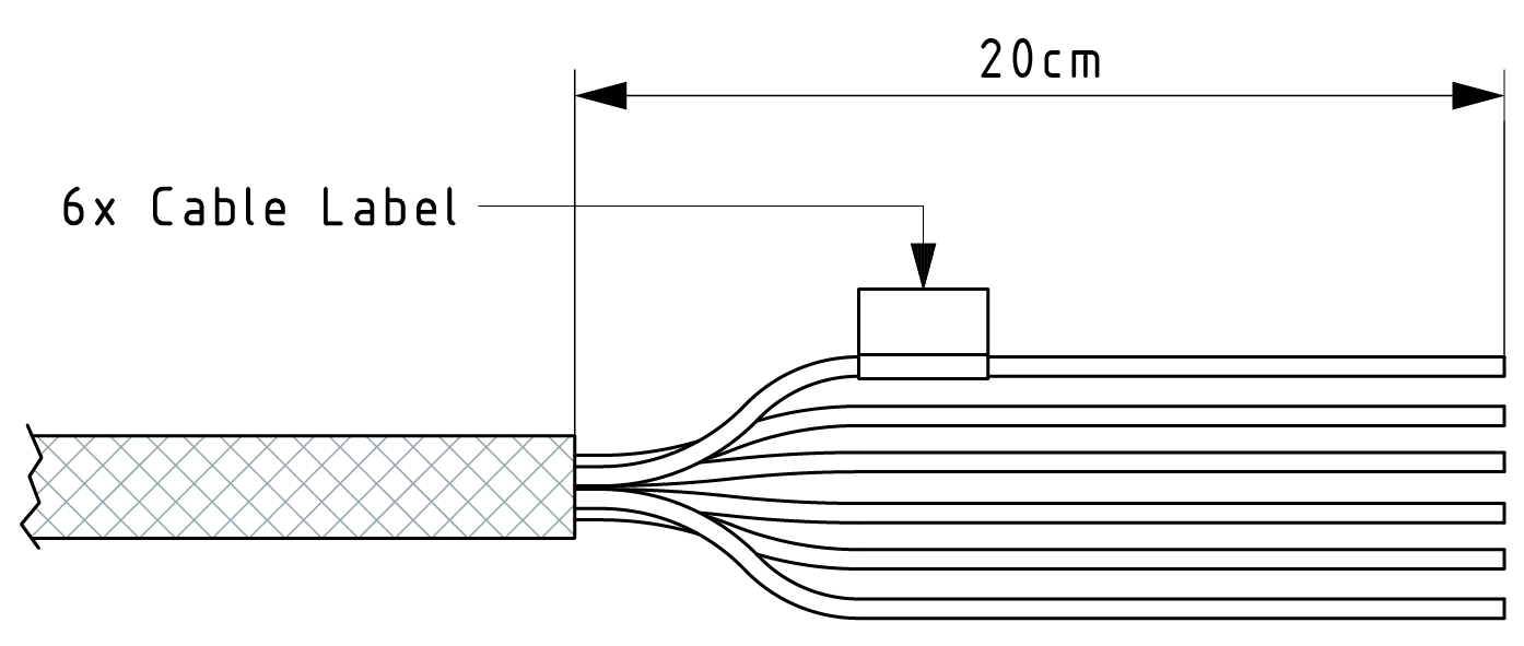
Starter Cable
The cable CLW4K Starter Cable 6open 2dsub 1pw 2m (part number 136000197) is equipped with the following connectors and open individual wires:
- 1 micro timer II socket,14-pin, female
- 2 D-sub, 9-pin, female (CAN1 and CAN2)
- 1 power connector
Starter cable: Individual wires
The open-end connectors are numbered on the strand ends.
The polarity also applies for the following cable:
- CLW4K starter cable 6 open, 2 D-Sub, 1 pw, 2 m (part number
136000197)
| Designation | Color | Description |
|---|---|---|
| Terminal 31 / ground | Green | Power supply |
| Analog input 1 | Yellow | I/O input |
| Analog input 2 | Gray | I/O input |
| Not used | ― | ― |
| Digital output | Blue | I/O output |
| Terminal 15 | Red | Input (ignition signal) |
Starter cable: Power supply cable
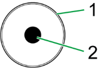
| Pin | Designation | Color | Description |
|---|---|---|---|
| 1 | Terminal 31 / ground | Green | Power supply |
| 2 | Terminal 30 / VCC | White | Power supply |
Starter cable: D-Sub connector (CAN1)
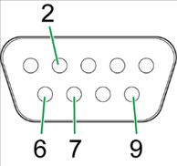
| Pin | Designation | Color | Description |
|---|---|---|---|
| 1 | not assigned | - | - |
| 2 | CAN1-Low | Brown-green | CAN, bidirectional |
| 4 | not assigned | - | - |
| 5 | not assigned | - | - |
| 6 | Terminal 31 / ground | Green | - |
| 7 | CAN1-High | White-green | CAN, bidirectional |
| 8 | not assigned | - | - |
| 9 | Terminal 30 / VCC | White | Power supply |
The D-Sub connector (CAN1) connection is also equipped with a slide switch to complete a reset to the factory settings.
Note
For more information on how to perform a device reset, see Reset device (repair mode).
Starter cable: D-Sub connector (CAN2)
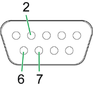
| Pin | Designation | Color | Description |
|---|---|---|---|
| 1 | not assigned | - | - |
| 2 | CAN2-Low | Red-blue | CAN, bidirectional |
| 3 | not assigned | - | - |
| 4 | not assigned | - | - |
| 5 | not assigned | - | - |
| 6 | Terminal 31 / ground | Violet | - |
| 7 | CAN2-High | Gray-pink | CAN, bidirectional |
| 8 | not assigned | - | - |
| 9 | not assigned | - | - |