Connectors
The device is equipped with the following connectors:
- 1 x Main plug connector, code 1 (14-pin)
- 1 x RF antenna connector - FAKRA, code I (male)
(Type4003only)
Note
The connector performance is certified for this minimum number of mating cycles:
- Main plug connector: 10 cycles
- FAKRA (antenna) plug: 100 cycles
If the number of mating cycles exceeds these guidelines, plug characteristics (e.g. electrical contact resistance, IP protection) may lie outside those specified; meaning, the mating cycles can be carried out without quality problems at least for the minimum numbers of mating cycles.
The CANlink wireless system is not designed for a high number of mating cycles.
Ideally the device is configured with an adapter cable from the Launch Kit in the first instance and in the second step installed and cabled within the machine.
Main plug connector
Use the main plug connector to connect the device to the CAN bus and supply it with power.
For the pin assignment of the main plug connector, see the following overview.
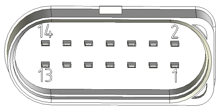
| Pin | Designation | Description |
|---|---|---|
| 1 | Terminal 30 / VCC | Power supply |
| 2 | Factory setting 1 | Input |
| 3 | Terminal 31 / ground | Power supply |
| 4 | Analog input 1 | I/O input |
| 5 | Analog input 2 | I/O input |
| 6 | Not used | - |
| 7 | Digital output | I/O output |
| 8 | Terminal 15 | Input (ignition signal) |
| 9 | Factory setting 2 | Input |
| 10 | Terminal 31 / ground | Power supply |
| 11 | CAN2-High | CAN, bidirectional |
| 12 | CAN2-Low | CAN, bidirectional |
| 13 | CAN1-High | CAN, bidirectional |
| 14 | CAN1-Low | CAN, bidirectional |
Note
Risk of property damage
Leakage and contamination due to an increased number of mating cycles and improper disconnecting of the main plug connector.
- Make sure the device is switched off during installation.
- Do not forcibly lever the main plug connector off the device connector.
- Refer to the handling manual from the manufacturer at Automotive Connectors/DeyTrade Connecting - Handling Manual FEP Sealed Connectors
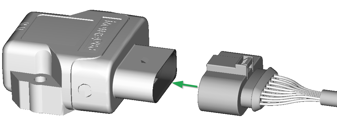
Connect main plug connector
Carefully connect the cable with the main plug connector. When connecting the plug, there must be a clear audible click.
Then the lock is correctly engaged.
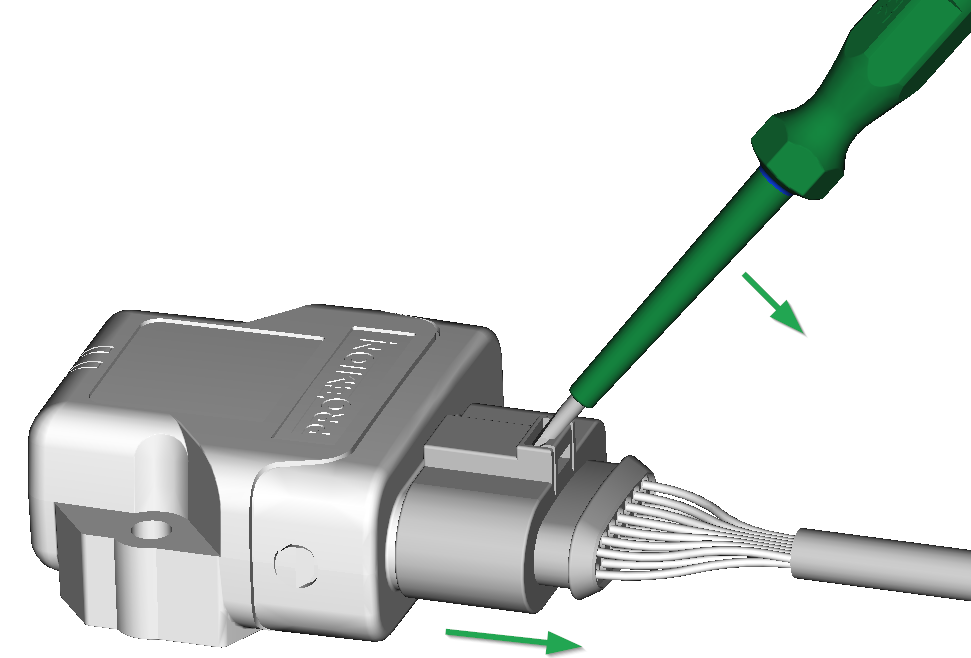
Disconnect main plug connector
Use an appropriate flat-blade screwdriver to release the lock. To do this, insert the screwdriver into the tab from above, then gently lever it down and back. At the same time, pull the plug slightly backwards by hand. If you can hear a click, the lock has been released and the connector can be removed.
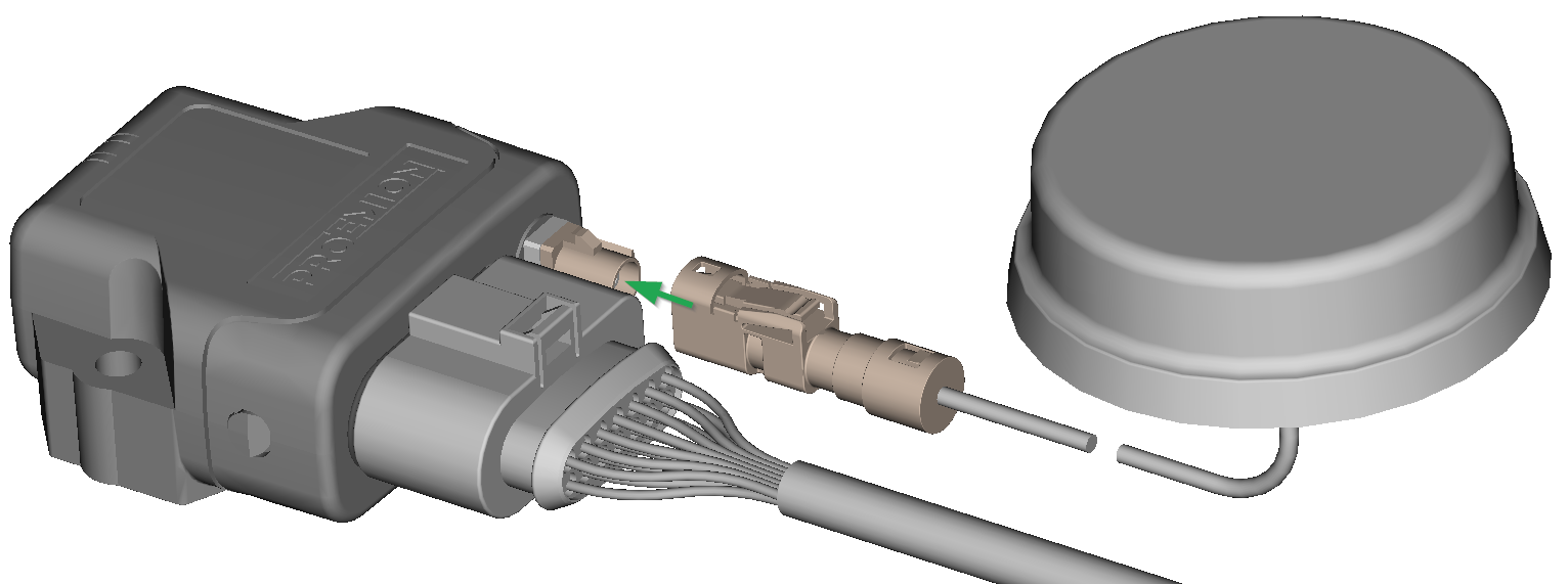
RF Antenna
Using the FAKRA antenna connector (on Type 4003), connect the device with an RF antenna to receive Wi-Fi® / Bluetooth signals.
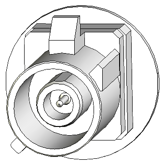
| Pin | Designation | Description |
|---|---|---|
| Inner pin | Signal | Wi-Fi® or Bluetooth signal |
| Outer pin (shielding) | Ground | Shielding/ housing |
Note
With Type 4001, antenna connector is replaced by an integrated antenna.
Note
The wireless antenna port is designed for a minimum number of 100 mating cycles. If the minimum number of mating cycles is exceeded, individual parameters could be out of the specification; meaning, the mating cycles can be carried out without quality problems at least for the minimum numbers of mating cycles. The basic function of the antenna port remains intact.
Connect antenna connector
Ensure that the coding of the BT/Wi-Fi® Antenna is matching the coding of the antenna connector at the CANlink® wireless 4000.
Carefully connect the antenna with the FAKRA connector.
When connecting the plug, there must be a clear audible click. Then the lock is correctly engaged.
Disconnect antenna connector
Release the marked lock and carefully pull the plug backwards.

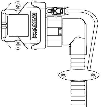
Cable Management
Note
Risk of property damage.
- Fasten the cable harness with a suitable strain relief near the main plug connector in order to avoid the transmission of any tension, strains or vibrations.
- Ensure that there is minimum bending radius of 8 times the outer diameter of the cable harness.
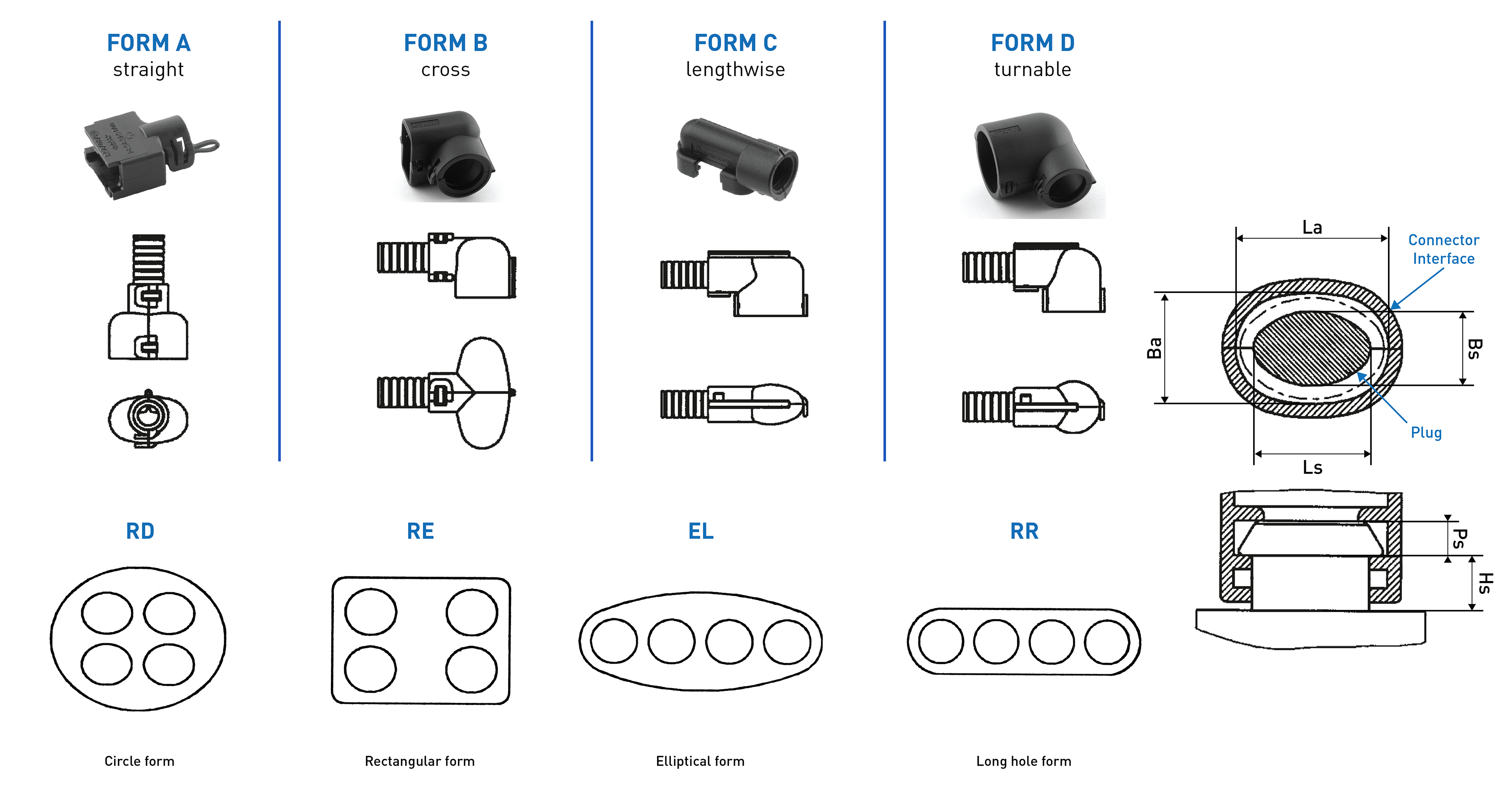
Protective Cover
Protect the connector and the cable with sufficient covers and cable tubing:
Warning
The following parts are not distributed by Proemion and can only be requested from the manufacturer with a minimum order quantity of 500 units, see Schlemmer.
The following part numbers from the supplier Schlemmer are recommended for the protective cover: 7807174, 7807207, 7807624:
Custom Cable for Main Plug
When creating a customized cable harness for the system integration of the CANlink® wireless 4000, some important recommendation for the setup of the main plug connector and cable must be considered.
It is recommended to use the connector components included in the Connector Kit, see Launch Kit to create a custom cable harness.
Note
Risk of property damage.
- This chapter contains some important advices. Please follow the instructions from the connector manufacturer and general rules for creating and protecting cable harnesses.
Note
Risk of property damage.
Water penetration due to capillary action of the cable strands.
- Ensure that both ends of the cable strands are sealed and assembled in the correct manner and in accordance to the manufacturer's specifications.
| Product | Recommendation |
|---|---|
 |
For the cable assembly it is essential that the instructions from the handling manual of the connector supplier are followed. Especially the main sealing, wire sealing and dummy plugs must be installed in the right manner. Refer to Automotive Connectors/DeyTrade Connecting - Handling Manual FEP Sealed Connectors. |
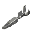 |
Use only the recommended tooling for machine processing. Refer to Connector Kit Datasheet. It is recommended to use tinned contacts. This corresponds the material of the pins |
 |
Use the wire sealing which fits to the outer diameter of the used wires |
 |
Cover the unused contact sockets with dummy plugs to protect the connection from dust and humidity |