CTO Demonstration 1
Here we demonstrate several usages of the Proemion CTO implementation with a CANlink® wireless 4000 device.
Namely sending a message:
-
On a Cyclic basis
We will send the Analog 1 voltage every 2s from the Server.
Sent to Cob-ID0x300. -
Cyclically if a condition is met
The current state of the Wireless Watchdog Timer Counter every second after 30s (until it resets at 10 minutes) from the Server.
Sent to Cob-ID0x303. -
On the occurrence of event
Every time a WiFi Client connects to the Server on port 30,001, send a connection state from the Server.
Sent to Cob-ID0x306. -
From one Client (Client2) via the MultiTalking Server to another Client (Client1).
Client2 sends its serial number every 2s via CAN2 to Cob-ID0x206.
| PDO | From | Destination |
|---|---|---|
| Analog 1 Voltage | Server | 0x300 |
| Wireless Watchdog Timer Counter | Server | 0x303 |
| Wi-Fi Connection State | Server | 0x306 |
| Serial Number | Client 2 | 0x206 |
We will also demonstrate sending different payloads on these triggers.
The PDOs will be transmitted on the local CANbus, and to all wirelessly connected peers (and their local bus).
Note
This walkthrough demonstrates:
- CTO transmission
- Wi-Fi MultiTalk networking
See MultiTalk. - Wireless Watchdog
See Wireless Watchdog. - Analog voltage input
See Analog Inputs.
DOD files are available that mirror this walkthrough:
clw4001_SetupPDOs_Server.DODclw4001_SetupPDOs_Client1.DODclw4001_SetupPDOs_Client2.DOD
(See DOD files for more information).
Connection Diagram
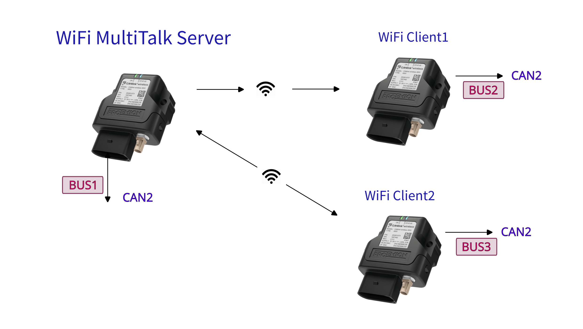
Server
- firmware version ≥ 2.3
- Channel 36 (5GHz)
- SSID:
PDO_Server - MultiTalk enabled
MultiTalk - IP Address: 192.168.0.34
- Listening on Ports 30000 & 30001
- Node ID CAN1: 0d34
- Node ID CAN2: 0d35
- Sends Analog 1 voltage every 2s to COB-ID
0x300 - Sends Wireless Watchdog Timer Counter every second to COB-ID
0x303 - Sends Connection State every time a Client connects to port 30001 to COB-ID
0x306
Client 1
- firmware version ≥ 2.3
- Node ID CAN1: 0d44
- Node ID CAN2: 0d45
- Connects to port 30000
Client 2
- firmware version ≥ 2.3
- Node ID CAN1: 0d54
- Node ID CAN2: 0d55
- Connects to port 30001
- Sends device serial number every 2s to Cob-ID
0x206
Server Walkthrough
Firstly, let's set up the CTO configuration, then continue with configuring the device as a 5GHz Wi-Fi Server.
CTO Configuration
-
Ensure firmware of Server is ≥ v2.3.
-
Open the Proemion Configurator.
-
Open a New configuration.
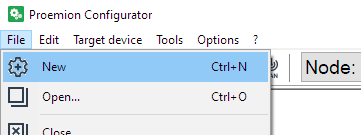
Figure 2: New Configuration -
You can see two devices under Local Connectivity Gateways
Select the correct one, according to your device.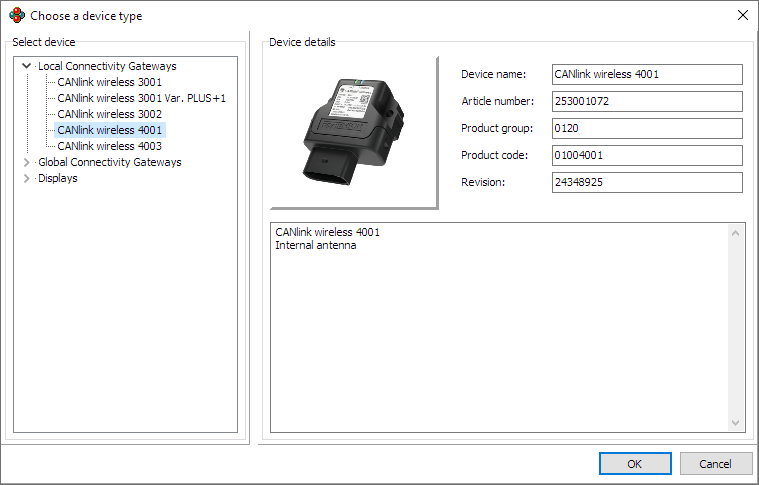
Figure 3: Choose Device Type -
Add DOD Information, and save as required
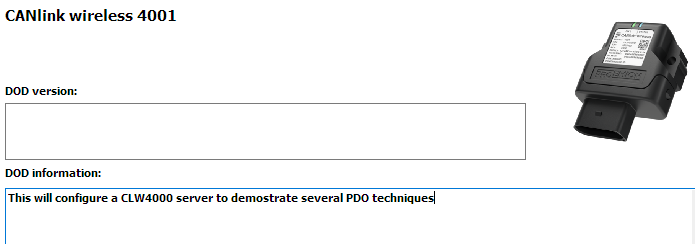
Figure 4: Save DOD Information -
Add a new 'Custom CAN Communication' folder.
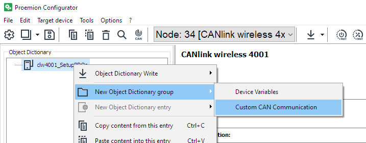
Figure 5: Custom CAN Communication -
Add 'Transmit PDO Messages (PDOs)' to this folder.
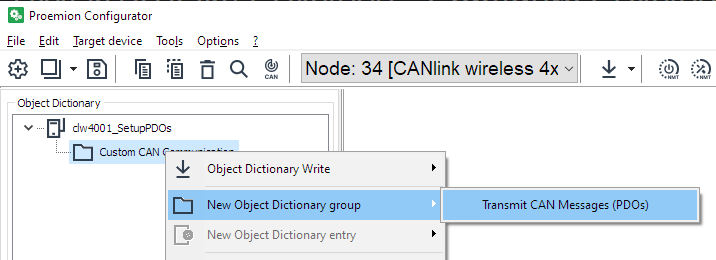
Figure 6: Transmit CAN messages -
Add the appropriate number of PDOs.
We are setting up three PDOs in this example:- Analog Voltage 1
- Wireless Connection State 2
- Wireless Interface Watchdog Tick
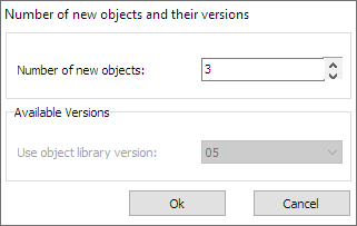
Figure 7: Add three PDOs -
Device variables must be added in order to be sent as PDOs.
In this example, we will send:-
Analog Voltage 1
-
Wireless Connection State 2
-
Wireless Interface Watchdog Tick
-
-
First, we must add the appropriate Device Variables.
Add a 'Device Variables' group.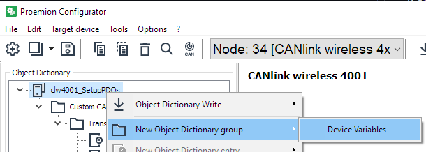
Figure 8: Add Device Variables -
As well as the three values we are transmitting, we base a decision on a forth Device Variable (Wireless Interface Watchdog Tick) - so add that too.
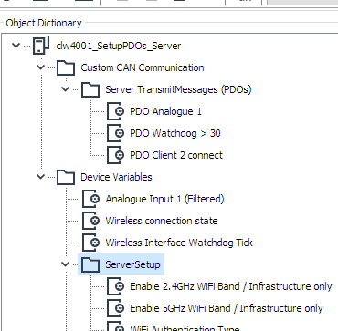
There should be the following Device Variables: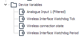
Figure 9: Device Variables Added -
Rename PDOs as required to match the function.
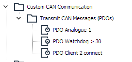
Figure 10: Rename Server PDOs
Set Cyclic Analog Voltage
We will configure the transmission of a single Device Variable in the Object Dictionary (OD) to be sent on a periodic basis.
It will be sent to COB-ID 0x300.
-
Click on the 'PDO Analogue 1' PDO under 'Custom CAN Communication'
-
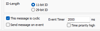
Here we set the timing of the message.
a. Select the CAN bus for transmission (2).
This will be sent on the physical as well as wireless bus.
b. CAN-ID length
c. It is a cyclic message with a specified frequency.
d. Destination COB-ID.
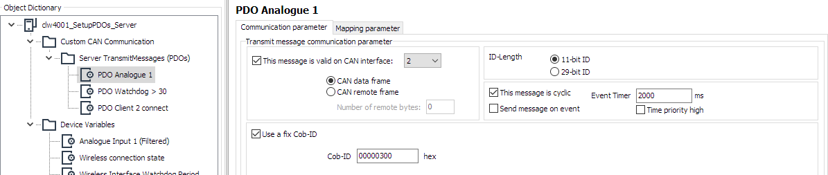
Figure 11: Set Analog Communication parameters -
Now that the transmission of the message has been defined, we specify the contents..
-
Click the 'Mapping parameter' tab to define the data to send.
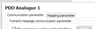
Figure 12: Mapping parameter -
Currently, no data is mapped into this PDO.
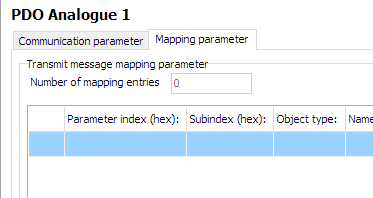
Figure 13: Analog Mapping parameter -
At the bottom is where we select the data to put into the message.
a. The data-type of the selected Device Variable is shown.
You can pack several Device Variables into the same PDO if they fit.
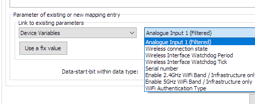
Figure 14: Analog Width
b. In this example, the Analogue Input is a 32bit real/float, so it takes up the entire PDO width.
You can align different data with the green fields.
c. Press 'New' when the field is correct. -
Items contained in this PDO are now listed.
(In this case, just one, but all data packed into the message will be listed).
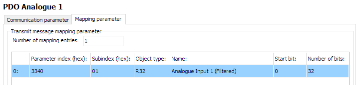
Figure 15: Analog Input Listed -
The first PDO has been configured.
Cyclically if a condition is met
This configuration sends a message periodically only if some condition is met.
This example will send current state of the Wireless Watchdog Timer Counter (how many seconds since initializing the watchdog timer) every second after 30s (until the device resets at 10 minutes) from the Server.
The message will be sent to Cob-ID 0x303.
-
Configure as in the image:
a. Suitable CAN bus (2)
b. Appropriate period (1000ms)
c. Select 'Cyclic' and 'Send message on event'
d. Configure destination COB-ID
e. The lower half of this page determines the condition that must be met in order to trigger sending the message (at the appropriate time).
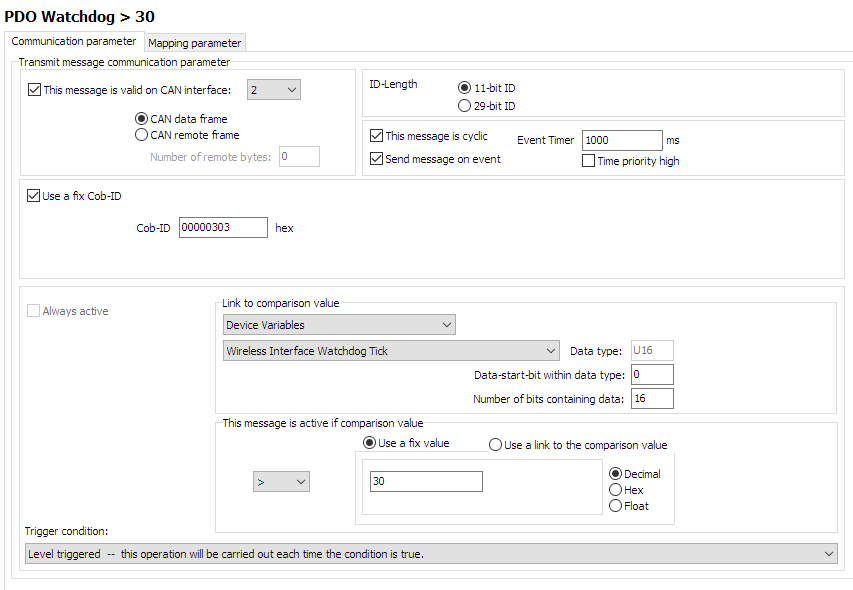
Figure 16: Server Watchdog PDO configuration
f. It can be seen that if the Device Variable 'Wireless Interface Watchdog Tick' is greater than 30, then the message can be sent.
Every time the timer is triggered, this evaluation will be checked.
Since this value increases every second, this message will begin to be transmitted 30 seconds after boot. -
Configure the contents in a similar way as we did before with the Analog Input CTO.
In this example, we will send the contents of the Tick itself, so we can see the value increasing every second.
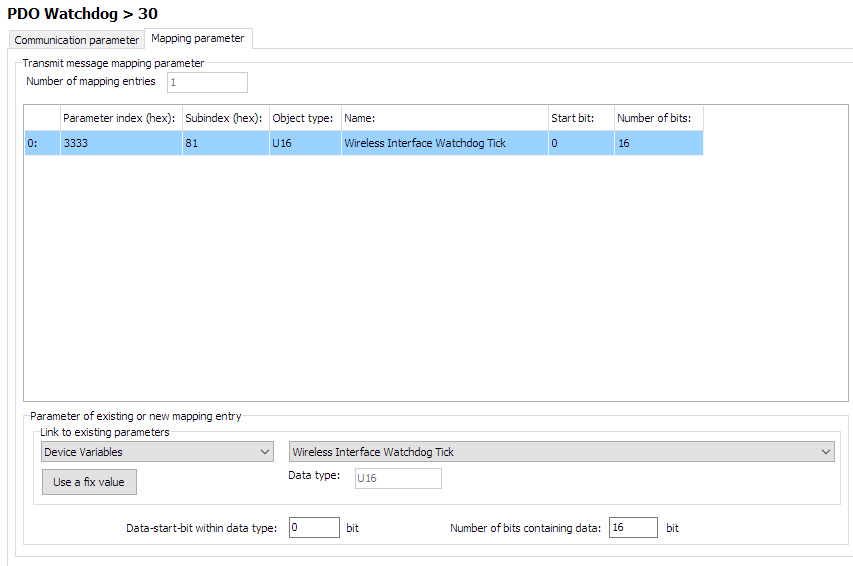
Figure 17: Server Watchdog PDO contents -
Enable the WIreless Interface Watchdog
Set0x3333:0x80 [Wireless Interface Watchdog Period]to 600 (decimal) to timeout after 10 minutes.
Event-driven message
Here we configure a message every time some event happens - regardless of time.
In this example, every time a Client device connects to port 30,001, we will send the Connection State to COB-ID 0x306.
-
Select only 'Send message on event'.
-
The comparison value will be the 'Connection State 2' which changes to
1on successful connection, then back to0when the connection is lost.
For this, we can use a fixed value for the comparison.
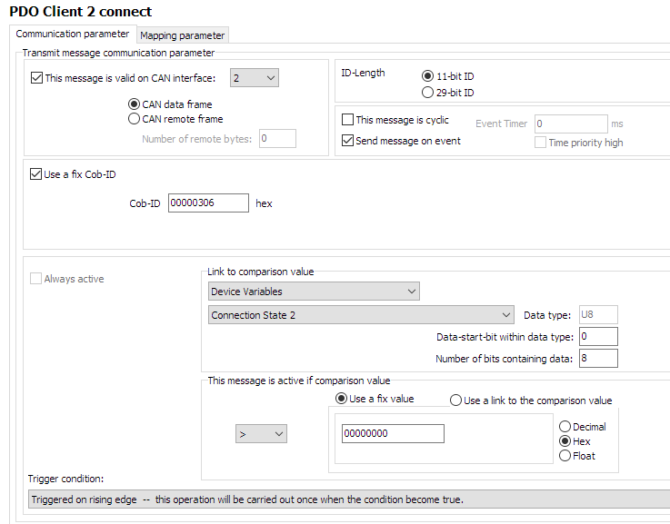
Figure 18: Server Connection PDO configuration -
Configure the contents of the message - in this case, the state of connection, itself.
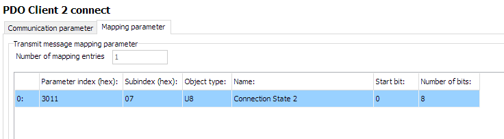
Figure 19: Server Connection PDO contents
5GHz Wi-Fi Server Configuration
Now that the DOD has been set up for transmitting CTOs, let's configure the device as a Server, so that Clients may connect to it:
For simplicity, create a new group 'ServerSetup' in the 'Device Variables' folder to contain device variables not involved in the CTOs.
This will be basically a standard 5GHz Wi-Fi Server, with MultiTalk enabled.
Add the following Device Variables, with the following settings (change highlighted objects as necessary):
| Object | Setting | Notes |
|---|---|---|
0x3000:0x01 [Wi-Fi Operating Mode] |
0x02 [Mini Access Point] |
|
0x3000:0x10 [Enable 2.4GHz WiFi Band / Infrastructure only] |
0 Disabled |
|
0x3000:0x11 [Enable 5GHz WiFi Band / Infrastructure only] |
1 Enabled |
|
0x3008:0x03 [Bluetooth Enable] |
0 Disabled |
|
0x3008:0x09 [BLE Enable] |
0 Disabled |
|
0x3008:0x02 [WiFi Enable] |
1 Enabled |
|
0x3000:0x04 [WiFi Authentication Type] |
7 [WPA/WPA2 Mixed] |
|
0x3000:0x09 [WiFi DCHP Mode] |
2 [Server (WiFi MiniAP only)] |
|
0x3000:0x25 [WiFi Region] |
As Appropriate | |
0x3000:0x02 [WiFi SSID] |
PDO_Server | |
0x3000:0x05 [WiFi Authentication Key] |
ChocolateCake4Breakfast! | |
0x3000:0x0F [Access Point WiFi Channel / MiniAP only] |
36 |
|
0x3008:0x04 [MultiTalk Enable] |
1 [Enabled] |
For Client 2 -> Client 1 communications |
0x4054:0x10 [Forward all CANOpen messages] |
1 [Forward] |
|
0x3010:0x15 [Connection Direction Configuration/Server or Client 1] |
2 [Server enabled] |
For Client 1 |
0x3010:0x16 [Connect Type 1] |
1 [TCP Socket] |
For Client 1 |
0x3010:0x17 [URL Address/WiFi Client only 1] |
192.168.0.34 |
For Client 1 |
0x3010:0x18 [Socket Listen Port/WiFi only 1] |
30000 |
For Client 1 |
0x3011:0x15 [Connection Direction Configuration/Server or Client 2] |
2 [Server enabled] |
For Client 2 |
0x3011:0x16 [Connect Type 2] |
1 [TCP Socket] |
For Client 2 |
0x3011:0x17 [URL Address/WiFi Client only 2] |
192.168.0.34 |
For Client 2 |
0x3011:0x18 [Socket Listen Port/WiFi only 2] |
30001 |
For Client 2 |
0x4000:0x16 [CAN Message Output CAN2] |
1 [Start Msg. Output active] |
|
0x4050:0x03 [Node Id CAN 1] |
34 |
|
0x4050:0x04 [Node Id CAN 2] |
35 |
Program the Device
We have finished configuring the setup.
Now we must program the new configuration.
-
Establish a connection to the device.
Be sure to do a node-scan to select the correct device. -
Select '(Download) All Entries and Reset'.
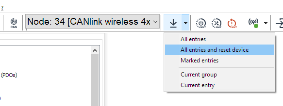
Figure 20: Download All Entries -
'Start'
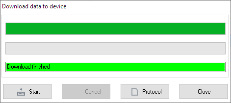
Figure 21: Download to Device -
Reboot the device.
Client 1 Walkthrough
Client 1 connects to the Server on port 30000.
It sends no PDOs, but receives them.
It is just a typical CLW4000 5GHz Wi-Fi bridge Client.
Add the following Device Variables, with the following settings (change highlighted objects as necessary):
| Object | Setting |
|---|---|
0x3000:0x01 [Wi-Fi Operating Mode] |
0x01 [Infrastructure] |
0x3000:0x10 [Enable 2.4GHz WiFi Band / Infrastructure only] |
0 Disabled |
0x3000:0x11 [Enable 5GHz WiFi Band / Infrastructure only] |
1 Enabled |
0x3008:0x03 [Bluetooth Enable] |
0 Disabled |
0x3008:0x09 [BLE Enable] |
0 Disabled |
0x3008:0x02 [WiFi Enable] |
1 Enabled |
0x3000:0x04 [WiFi Authentication Type] |
7 [WPA/WPA2 Mixed] |
0x3000:0x09 [WiFi DCHP Mode] |
1 [DHCP Client (WiFi infrastructure only)] |
0x3000:0x25 [WiFi Region] |
As Appropriate |
0x3000:0x02 [WiFi SSID] |
PDO_Server |
0x3000:0x05 [WiFi Authentication Key] |
ChocolateCake4Breakfast! |
0x3010:0x15 [Connection Direction Configuration/Server or Client 1] |
3 [Client enabled] |
0x3010:0x16 [Connect Type 1] |
1 [TCP Socket] |
0x3010:0x17 [URL Address/WiFi Client only 1] |
192.168.0.34 |
0x3010:0x18 [Socket Listen Port/WiFi only 1] |
30000 |
0x4050:0x03 [Node Id CAN 1] |
44 |
0x4050:0x04 [Node Id CAN 2] |
45 |
Program as above.
Client 2 Walkthrough
Client 2 connects to the Server on port 30001.
It sends its Serial Number as a PDO every 2s to Cob-ID 0x206.
Every device on the bus will receive this message, because the Server has enabled MultiTalk.
Device Variables
Add the following Device Variables, with the following settings (change highlighted objects as necessary):
| Object | Setting |
|---|---|
0x3000:0x01 [Wi-Fi Operating Mode] |
0x01 [Infrastructure] |
0x3000:0x10 [Enable 2.4GHz WiFi Band / Infrastructure only] |
0 Disabled |
0x3000:0x11 [Enable 5GHz WiFi Band / Infrastructure only] |
1 Enabled |
0x3008:0x03 [Bluetooth Enable] |
0 Disabled |
0x3008:0x09 [BLE Enable] |
0 Disabled |
0x3008:0x02 [WiFi Enable] |
1 Enabled |
0x3000:0x04 [WiFi Authentication Type] |
7 [WPA/WPA2 Mixed] |
0x3000:0x09 [WiFi DCHP Mode] |
1 [DHCP Client (WiFi infrastructure only)] |
0x3000:0x25 [WiFi Region] |
As Appropriate |
0x3000:0x02 [WiFi SSID] |
PDO_Server |
0x3000:0x05 [WiFi Authentication Key] |
ChocolateCake4Breakfast! |
0x3010:0x15 [Connection Direction Configuration/Server or Client 1] |
3 [Client enabled] |
0x3010:0x16 [Connect Type 1] |
1 [TCP Socket] |
0x3010:0x17 [URL Address/WiFi Client only 1] |
192.168.0.34 |
0x3010:0x18 [Socket Listen Port/WiFi only 1] |
30001 |
0x4050:0x03 [Node Id CAN 1] |
54 |
0x4050:0x04 [Node Id CAN 2] |
55 |
Also add 0x1018:0x04 [Serial Number] as a Device Variable in order to be able to send it in the next step configuring PDO.
| Object | Setting |
|---|---|
0x1018:0x04 [Serial Number] |
(Used for reading only) |
PDO configuration
Overview
- Add one PDO, rename as necessary
-
Setup a cyclic message, transmitting every 2 seconds to
0x206
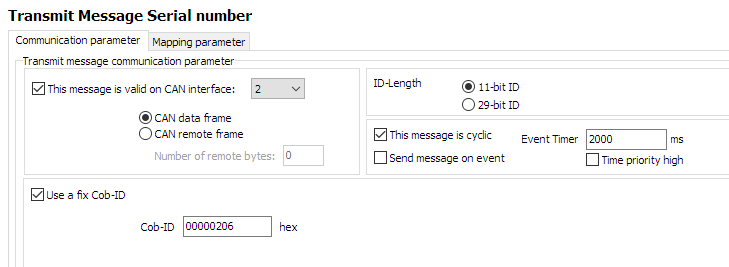
Figure 22: Client2 CTO Configuration -
Configure Mapping Parameter, using the
0x1018:0x04 [Serial Number]
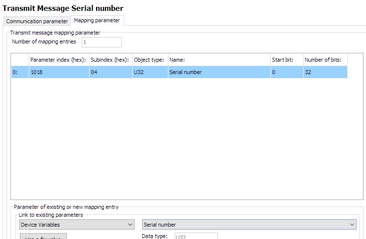
Figure 23: Client2 CTO Configuration
Steps
-
List is initially empty
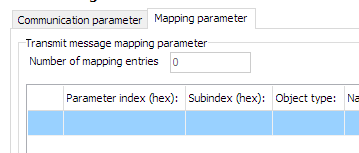
Figure 24: Client2 mapping -
Select 'Device Variables' for
Link to existing parameters
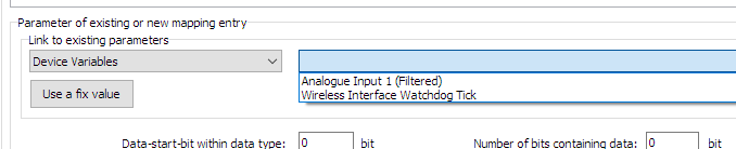
Figure 25: Client2 mapping -
Select appropriate Device Variable to transmit
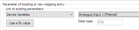
Figure 26: Client2 mapping -
Add number of databits as appropriate
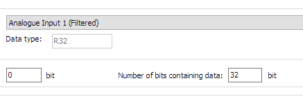
Figure 27: Client2 mapping -
Click "New" to add to mapping parameters
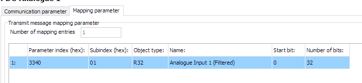
Figure 28: Client2 mapping
Set cyclic message
- Define period of message
Testing CTO Demo
Firstly, write all configurations to the three devices:
- The Server CAN 2 Node ID should be
35. - Client 1 CAN 2 Node ID should be
45. - Client 2 CAN 2 Node ID should be
55.
Using your CANopen diagnostics tool of choice, you should be able to verify the following functions are operating as expected:
- Periodically
- Event-driven
- MultiTalk
Periodically
- The Server device will output the Analog voltage PDO to
0x300every two seconds on the virtual (wireless) connection as well as the physical CAN2 bus. -
The Server device will output the Wireless Interface Watchdog Tick value to
0x303:a. increasing by one every second.
b. starting after the value is greater or equal to 30.
c. until the device resets after ten minutes, at which point the process will begin again.
(There will have been 600 - 30 = 570 messages sent). -
Client2 will send its
0x1018:0x04 [Serial Number]every second to0x206to the CAN2 virtual (wireless) and physical bus.
Event-driven
- Every time Client2 is powered on and connects to the Server, the Server will output a single
0x3001:08 [Wireless connection state]PDO to0x306.
Power-off Client2 and back on again, and after a few seconds (while the connection is being established), the Server will output one more identical message.
MultiTalk
Since MultiTalk is enabled on the Server, every device connected to the CAN2 bus will receive the Client2 0x1018:0x04 [Serial Number] CTO.
This means every device connected wirelessly, and also all every CAN2 device connected physically to those devices.
Tip
When MultiTalk is enabled, CAN traffic can saturate the connection between all connected devices.
Consider enabling Filters.