1. Preamble
1.1. Legal Notice
All brands and trademarks named in this document and possibly protected by third-party rights are subject without limitation to the terms of the valid trademark law and intellectual property rights of their respective registered owner.
You can find a list of the free-source and open-source software as well as copyright notes, license texts and, if applicable, the relevant source code on our website under the link: Free & Open Source Software
Observe all local and regional laws and provisions as well as the safety instructions contained in this document.
1.2. Contact
Proemion GmbH
Donaustr. 14
36043 Fulda, Germany
Phone: +49 661 9490-0
Fax: +49 661 9490-111
info@proemion.com
Proemion Corp.
US Subsidiary
241 Taylor St., Suite 301
Dayton, Ohio 45402, USA
Phone: +1 937 558 2211
Fax: +1 937 641 8787
info-dayton@proemion.com
Proemion Ltd.
373 Gangnam-daero Seocho-gu
Seoul, 06621, South Korea
Phone: +82 2 6080 9490
Fax: +82 504 484 9490
info-seoul@proemion.com
Website: Proemion
1.3. About This Manual
This document is part of the product and provides important information on the intended use, safety, installation, and operation of the devices described below. The document is intended for qualified technicians and electricians with advanced knowledge in electrical engineering and field bus systems, allowing them to estimate the risks and hazards of operating the device and to integrate it into systems with components of other manufacturers.
1.3.1. Safety Levels
The safety levels have the following meanings:
|
Severe injury or death. Probability: very high |
|
Severe injury or death. Probability: possible |
|
Slight or medium injury. Probability: possible |
|
Property damage. |
1.3.2. Symbols and formatting
The following symbols and formatting help you recognize the purpose of the
paragraphs:
|
|
|
|
|
|
| Symbol | Description |
|---|---|
|
Application options for the devices described. |
|
Indicates references to other documents, websites, etc. |
|
Description of different types. Data and descriptions that only apply to certain types are either covered in separate chapters or marked with the symbol shown here. |


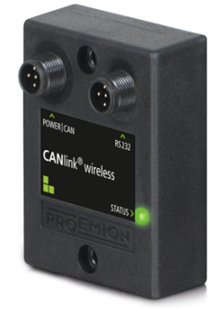
2. About the Device
This chapter provides an overview of the device’s operating elements and functions as well as the intended use of the device. Additionally, it provides an overview of the available model variants and certificates.
For more detailed information, see Chapter Annex.
2.1. Important Device Information
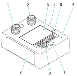
2.1.1. Device Elements
| # | Item |
|---|---|
1 |
CAN/Power - connector |
2 |
RS232 - connector |
3 |
Front label |
4 |
Type label B |
5 |
LED |
6 |
Housing |
7 |
Mounting holes |
8 |
RF antenna connector |
9 |
Type label A |
|
|
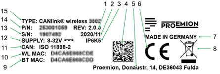
2.1.2. Type Label
The type label part A provides the following information:
| # | Item |
|---|---|
1 |
Hardware version |
2 |
Date of production |
3 |
Protection class |
4 |
Traceability code |
5 |
Manufacturer address |
6 |
CE mark |
7 |
Country of origin |
8 |
Disposal symbol |
9 |
Bluetooth MAC address |
10 |
WLAN MAC address |
11 |
CAN standard |
12 |
Power supply |
13 |
Serial number |
14 |
Article number |
15 |
Device name and type |
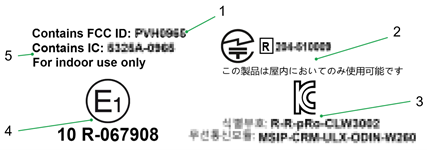
The type label part B provides the following information:
| # | Item |
|---|---|
1 |
FCC-ID |
2 |
Japan radio equipment compliance |
3 |
Korean KCC certification |
4 |
ECE certification mark |
5 |
IC-ID |
|
|
Traceability code
The traceability code contains the following information.
Example:
253001058000000000001907492(W)D4CA6E868CDE(B)D4CA6E868CDD
| Item | Description |
|---|---|
9-digit part number: |
|
Serial number 0-padded: |
|
|
|
|
|
2.1.3. Intended Use
The device provides access to the CAN data of a vehicle or machine in various operating modes:
CAN-CAN Bridge: wireless transmission of CAN data between CANlink wireless devices, e.g. as a substitute for CAN cables in drag chains or with remote control units.
CAN-Bluetooth Interface: wireless transmission of CAN data to a Bluetooth terminal device.
CAN-WLAN Interface: wireless transmission of CAN data to devices in the wireless network.
In Interface mode, CAN data can be transmitted to other WLAN/Bluetooth devices such as PCs, smartphones, and tablets for displaying and evaluation of data.
The device is suitable for use in mobile and stationary systems for industry, small business, and in agricultural and forestry machinery.
|
The 3001 model variant can be used in environments that require protection class IP6K7.
The 3002 model variant can be used in environments that require protection class IP6K5.
|
Only use the device within the permitted temperature range and the other parameters specified in the technical data.
Any use other than that described under “Intended use” is considered unintended use.
MISUSE
The device does not comply with Directive 2014/34/EU and may not be used in potentially explosive areas.
QUALIFIED PERSONNEL
The device must only be put into operation by qualified technicians and electricians with advanced knowledge of electrical engineering and fieldbus systems.
The specialist personnel must know the contents of this manual and always have access to it.
|
|
2.1.4. Conformity
For details of the corresponding approval tests, see Certification and Qualification.
The device meets the requirements of the following standards and legal requirements:
|
CE Compliant |

|
FCC Compliant |

|
E1 Compliant |

|
KCC Compliant |
|
2.2. Device Functions
The available model variants differ in the external antenna connector.
With the device, you can transmit and receive CAN data via a WLAN or Bluetooth connection. It can also be used as a CAN-CAN Bridge or a CAN-Wireless Interface. You can find the WLAN standards and Bluetooth profiles supported in chapter Interfaces.
CAN-CAN Bridge:
The CAN-CAN Bridge replaces a CAN cable and transmits the CAN data between two CANlink wireless devices.
CAN-Wireless Interface:
The CAN-Wireless Interface transmits CAN data to other WLAN or Bluetooth-capable devices on which CAN data is logged and evaluated.
2.2.1. Available Models
| Model | CAN | Antenna | WLAN | Bluetooth |
|---|---|---|---|---|
CANlink wireless 3001 |
1 |
internal |
Yes |
Yes |
CANlink wireless 3002 |
1 |
external |
Yes |
Yes |
2.2.3. Starter Kits
Starter kits are available for the device containing the following components:
CANlink wireless 3001 starter kit
| Material | Qty |
|---|---|
CANlink wireless 3001 |
1 |
CAN cable M12 5-pin/D-Sub/Power terminal 15 ON |
1 |
CAN bus termination D-Sub / D-Sub CANterm 120 Ohm |
1 |
USB-RS232 converter cable, M12 5-pin, 1.8m |
1 |
Power supply unit |
1 |
Protection cap for flange plug M12 |
1 |
CANlink wireless 3001 Bridge starter kit
| Material | Qty |
|---|---|
CANlink wireless 3001 |
2 |
CAN cable M12 5-pin/D-Sub/Power terminal 15 ON |
2 |
CAN bus termination D-Sub / D-Sub CANterm 120 Ohm |
2 |
USB-RS232 converter cable, M12 5-pin, 1.8m |
1 |
Power supply unit |
2 |
Protection cap for flange plug M12 |
2 |
CANlink wireless 3002 starter kit
| Material | Qty |
|---|---|
CANlink wireless 3002 |
1 |
Dual band Bluetooth- / Wi-Fi Antenna tiltable 90° |
1 |
CAN cable M12 5-pin/D-Sub/Power terminal 15 ON |
1 |
CAN bus termination D-Sub / D-Sub CANterm 120 Ohm |
1 |
USB-RS232 converter cable, M12 5-pin, 1.8m |
1 |
Power supply unit |
1 |
Protection cap for flange plug M12 |
1 |
CANlink wireless 3002 Bridge starter kit
| Material | Qty |
|---|---|
CANlink wireless 3002 |
2 |
Dual band Bluetooth- / Wi-Fi Antenna tiltable 90° |
2 |
CAN cable M12 5-pin/D-Sub/Power terminal 15 ON |
2 |
CAN bus termination D-Sub / D-Sub CANterm 120 Ohm |
2 |
USB-RS232 converter cable, M12 5-pin, 1.8m |
1 |
Power supply unit |
2 |
Protection cap for flange plug M12 |
2 |
2.2.4. Software and Accessories
The software can be downloaded from our Download Center at the Document Library.
| Software | Source |
|---|---|
CANlink® wireless 3000 Configurator |
|
Remote Service Tool |
|
Proemion Firmware Programmer |
| Material | Part number |
|---|---|
Dual band Bluetooth- / Wi-Fi Antenna tiltable 90° |
|
ANT WLDB DA 2M0 RPSMA-M FA TBC |
|
CAN cable M12 5-pin/D-Sub/Power terminal 15 ON |
|
CAN cable M12 5-pin / open 2 |
|
PCAN-USB - CAN/USB Interface |
|
USB-RS232 converter cable , M12 5-pin, 1.8m |
|
Protection cap for connector M12 |
|
2.3. Service and Support
The latest versions of the drivers, software, firmware, and documentation are available in our Document Library.
Do you need help or want to report a bug?
Visit Proemion for more information, or raise a ticket at Support.
2.3.1. Firmware Updates and Support
|
3. Safety Information
This chapter contains important information on how to avoid life-threatening situations and injuries and how to prevent product damage.
3.1. Safety Instructions
|
|
|
|
|
|
|
|
|
|
|
3.2. FCC Notes
The devices described in this device manual may only be used in mobile or stationary systems in which the distance between antennas and persons is at least 20 cm. The antennas must further not be co-located or operated in conjunction with any other antennas or transmitters.
|
|
Changes or modifications to the device not expressly approved by the manufacturer can void the user’s authority to operate the device under FCC rules.
3.3. Warranty and Liability
Proemion assumes no liability for defects caused by normal wear, external influences and incorrect installation, operation or maintenance. This also applies if the customer or a third party modifies the devices, any accessories, or the software without permission from Proemion.
4. Functionality and Features
This chapter contains information on device functionality and features. It provides details of the operating modes, connectors, cables, pin assignments, interfaces and indicator elements.
4.1. Functions
| Function | 3001 | 3002 |
|---|---|---|
CAN-Bluetooth Interface |
Yes |
Yes |
CAN-CAN-Bluetooth Bridge |
Yes |
Yes |
CAN-WLAN Interface |
Yes |
Yes |
CAN-CAN-WLAN Bridge |
Yes |
Yes |
4.1.1. CAN-Bluetooth Interface
In operation as a CAN-Bluetooth Interface, CAN data is transmitted wireless to other Bluetooth-capable devices such as PCs, smartphones, or tablets.
4.1.2. CAN-WLAN Interface
In operation as a CAN-WLAN Interface, CAN data is transmitted wireless to other Bluetooth-capable devices such as PCs, smartphones, or tablets.
4.1.3. CAN-CAN-Bluetooth Bridge
In operation as a CAN-CAN-Bluetooth Bridge, CAN data is transmitted wireless between two CANlink® wireless 3000 devices via a Bluetooth connection. The CAN-CAN-Bluetooth Bridge acts as a substitute for CAN cables, e.g. in drag chains or remote control units.
4.1.4. CAN-CAN-WLAN Bridge
In operation as a CAN-CAN-WLAN Bridge, CAN data is transmitted wireless between two CANlink® wireless 3000 devices via a WLAN connection. The CAN-CAN-WLAN Bridge acts as a substitute for CAN cables, e.g. in drag chains or remote control units.
4.1.5. Use Cases Overview
The following table shows the possible applications with the CANlink wireless.
(P2P is the abbreviation for point to point connection)
| Application | Connection Method | Remarks | Client Software |
|---|---|---|---|
CAN – Mobile Device / PC Interface, |
Bluetooth Classic |
- |
Remote Service Tool, or a 3rd Party App for Android or iOS via Byte Command Protocol API |
CAN – Mobile Device / PC Interface, |
WLAN Access Point mode |
- |
Remote Service Tool, or a 3rd Party App for Android or iOS via Byte Command Protocol API |
CAN – Mobile Device / PC Interface, |
WLAN Infrastructure mode |
WLAN Infrastructure Mode requires an external Access Point |
Remote Service Tool, or a 3rd Party App for Android or iOS via Byte Command Protocol API |
CAN – CAN Bridge P2P connection |
Bluetooth Classic |
Recommended communication technology for CAN-CAN bridge |
n.a. |
CAN – CAN Bridge, |
Bluetooth Classic |
If there is more than one client in the range of the SPP server module, the fastest client will establish the connection. |
n.a. |
CAN – CAN Bridge, |
WLAN Access Point mode |
- |
n.a. |
CAN – CAN Bridge, |
Bluetooth Classic, WLAN infrastructure mode or WLAN access point mode |
Bluetooth mode is recommended. |
n.a. |
4.2. Connectors
The device is equipped with the following connectors:
-
1x CAN / power connector
-
1x RS232 connector
-
1x RF antenna connector (only model variant 3002)
4.2.1. CAN / Power Connector
Use the CAN / power connector to connect the device to the CAN bus and supply it with power. For the pin assignment of the CAN connector, see the following overview.
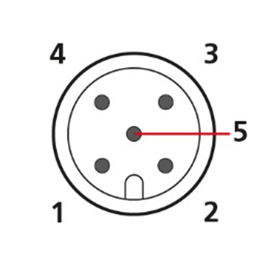
| Pin | Designation | Description |
|---|---|---|
1 |
Ground |
Power supply / reference ground |
2 |
VCC (8-32 VDC) |
Power supply |
3 |
Terminal 15 (digital input) |
Terminal 15 / Ignition I/O |
4 |
CAN-High |
CAN |
5 |
CAN-Low |
CAN |
|
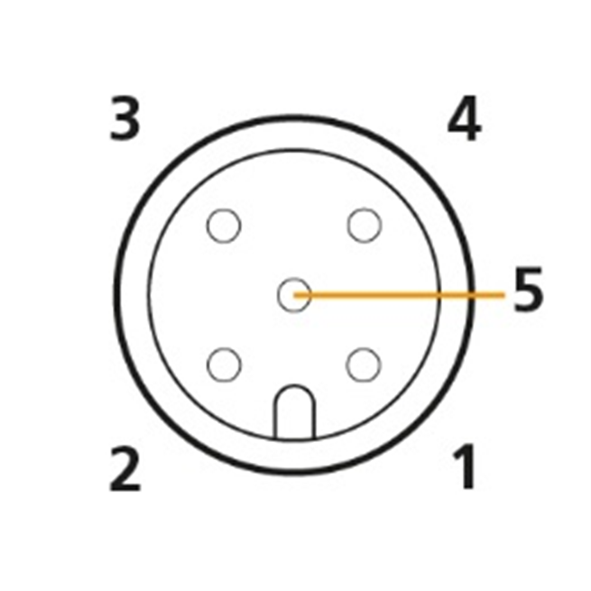
4.2.2. RS232 Connector
Use the RS232 connector to connect the device to a PC. Configuration and firmware updates are transferred to the device via the RS232 connector. You can find instructions on loading firmware updates in chapter Firmware update. For the pin assignment of the RS232 connector, see the following overview.
| Pin | Designation | Description |
|---|---|---|
1 |
Ground |
Power supply / reference ground |
2 |
- |
- |
3 |
BOOT (DSR) |
Input, BOOT pin (data set ready) |
4 |
RXD |
RS-232 receive (input) |
5 |
TXD |
RS-232 transmit (output) |
|
|
Further information regarding the configuration can be found in the manual for the CANlink® wireless Configurator Manual. |
4.2.3. RF Antenna
Using the RP-SMA antenna connector, connect the device (model variant 3002) with an RF antenna to receive WLAN Bluetooth signals.Using the RP-SMA antenna connector, connect the device (model variant 3002) with an RF antenna to receive WLAN Bluetooth signals.
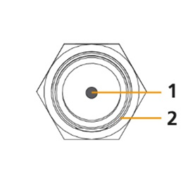
| Pin | Designation | Description |
|---|---|---|
1 |
Signal |
WLAN or Bluetooth signal |
2 |
Ground |
Shielding/ housing |
|
4.3. Indicator Element (LED)
The front of the device features a two-color LED for indicating function and status.
|
The following tables show possible LED states:
| Color | Status | Meaning |
|---|---|---|
Red/green |
Off |
No data transfer. Device switched off or in sleep mode. For details about sleep mode, please refer to the manual for the CANlink® wireless Configurator Manual. |
Green |
On |
WLAN or Bluetooth connection active. |
Green |
Blinking (200 ms on, 200 ms off) |
Rest status. The device is ready for connection. |
Green |
Single Flash (200 ms on, 1000 ms off) |
Pairing mode (Bluetooth). |
Green |
Double Flash (200 ms on, 200 ms off, 200 ms on, 1000 ms off) |
Initialization of the device. |
Green |
Triple Flash (200 ms on, 200 ms off, 200 ms on, 200 ms off, 200 ms on, 1000 ms off) |
Reset status. |
Red |
On |
Radio module malfunction, voltage critical or CAN error. |
Red |
Slow Blinking (500 ms on, 500 ms off) |
Repair mode ready. |
Orange |
Flashing (irregularly) |
Data transfer to and from other devices. |
Orange |
On |
Configuration mode or firmware update. |


4.4. Cables
4.4.1. CAN / Power Cable
The CAN cable M12 5-pin/D-Sub/Power terminal 15 ON (part number 136000187) has the following connectors:
-
1x M12 5-pin female
-
1x D-sub 9-pin female
-
1x power connector
CAN cable M12 5-pin/D-Sub/Power terminal 15 ON, M12 connector
| Pin | Designation | Color | Description |
|---|---|---|---|
1 |
Ground |
Brown |
Power supply |
2 |
VCC / terminal 30 |
White |
Power supply |
3 |
Terminal 15 / digital input |
Blue |
Input |
4 |
CAN-High |
Black |
CAN |
5 |
CAN-Low |
Gray, green |
CAN |
|
CAN cable M12 5-pin/D-Sub/Power terminal 15 ON, D-Sub connector
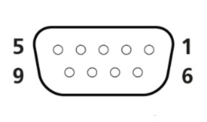
| Pin | Designation |
|---|---|
1 |
not assigned |
2 |
CAN-Low |
3 |
not assigned |
4 |
not assigned |
5 |
not assigned |
6 |
Ground |
7 |
CAN-High |
8 |
not assigned |
9 |
VCC |
4.4.2. RS232 connection cable
The USB-RS232 converter cable, M12 5-pin, 1.8 m (part number 257001017) features the following connectors:
-
1x M12 5-pin female
-
1x USB 2.0 male
|
USB-RS232 converter cable, M12 connector
| Pin | Designation | Description |
|---|---|---|
1 |
Ground |
Power supply / reference ground |
2 |
- |
not assigned |
3 |
BOOT (DSR) |
BOOT pin, RS-232 data set ready (output) |
4 |
TxD (out) |
RS-232 transmit (output) |
5 |
RxD (in) |
RS-232 receive (input) |

5. Getting Started
This chapter describes the first steps that are required for the initial commissioning of the device. Furthermore, it contains useful information on how to connect, configure, and mount the device.
5.1. Installing Software
Use the CANlink® wireless 3000 Configurator software to configure the device.
You can evaluate the transmitted data with the Remote Service Tool, a 3rd Party App for Android or iOS via Byte Command Protocol API.
Use the Proemion Firmware Programmer software for firmware updates.
|
The software can be downloaded from our Download Center at the Document Library |
| Software | Path on Download Center |
|---|---|
CANlink wireless Configurator |
01_Proemion_Devices\03_CANlink wireless 3000\04_Software |
USB driver |
05_Utilities\06_USB Drivers |
Remote Service Tool |
03_Proemion Tools Software\01_Software\04_Remote Service Tool |
Proemion Firmware Programmer |
03_Proemion Tools Software\01_Software\02_Proemion Firmware Programmer |
Execute the relevant application file (setup.exe, install.bat or similar) and follow the instructions on the screen to install the software on your PC.
5.2. Connecting the Device
|
|
|
If you have any questions or anything is unclear, please contact our support before getting started. See chapter Service and Support. |
5.2.1. Connecting an external antenna
The device (model variant 3002) features an RP-SMA antenna connector for connection of the RF antenna Bluetooth/WLAN antenna (part number 157000085).
| TIP You can request more information about other permitted RF antennas using the Proemion support form at Support. |
|
|
|
|
-
Connect the RF antenna to the RP-SMA connector of the device (model variant 3002).

|
5.2.2. CAN
Connect the device interfaces to the CAN bus whose data you want to log or send. For test purposes, connect the device to a PC using a communication gateway (e.g. PCAN-USB - CAN/USB Interface).
The CAN connection terminal CAN-High and CAN-Low signals must match the signals of the connector on the device. You can connect Ground of the supply connector with CAN-GND because there is no galvanic isolation.
The following table provides an overview of the CAN bit rates in relation to the bus length:
| CAN baudrate | Maximum bus length |
|---|---|
1 Mbit/s |
25 m |
800 kbit/s |
50 m |
500 kbit/s |
100 m |
250 kbit/s |
250 m |
125 kbit/s |
500 m |
50 kbit/s |
1000 m |
5.2.3. CAN bus termination
In any bus system, signal reflections at the end of a wire or cable can cause interference which can in turn cause transmission errors. To minimize these reflections, place a terminator at each end of transmission lines. The terminating resistance between CAN-High and CAN-Low must match the characteristic impedance of the transmission cables. In CAN bus networks, normally unshielded, twisted cable pairs are used for signal transmission. The characteristic impedance of the transmission lines is roughly 120 Ω. The terminator between CAN-High and CAN-Low must be 120 Ohm.
5.2.4. Power supply
The device is supplied with power via the CAN connector.
|
5.2.5. Connection with a PC via RS232
To connect the device with a PC for configuration purposes, you need the CAN cable M12 5-pin/D-Sub/Power terminal 15 ON (part number 136000187), the power supply unit applicable for your country, and the USB-RS232 converter cable, M12 5-pin, 1.8 m (part number 257001017) from the Starter Kits.
-
Install the USB driver pack and CANlink® wireless 3000 Configurator from the Download Center onto the PC. See chapter Installing Software.
-
Connect the device with the CAN cable M12 5-pin/D-Sub/Power terminal 15 ON to the power grid using the country-specific power supply unit from the starter kit.
-
Connect the device to the PC with the USB-RS232 converter cable, M12-5-pin, 1.8 m.
 Figure 14. Connecting the CANlink® wireless 3000 to the PC for configuration
NOTICE
Connection problems due to faulty screw connection of the cap nut to the RS232 connector.
Insufficient data transmission and connection problems.
- Screw the M12 5-pin angle plug correctly to the RS232 connector using the cap nut. -
Identify the virtual COM port of the device in the PC Device Manager under USB Serial Port.
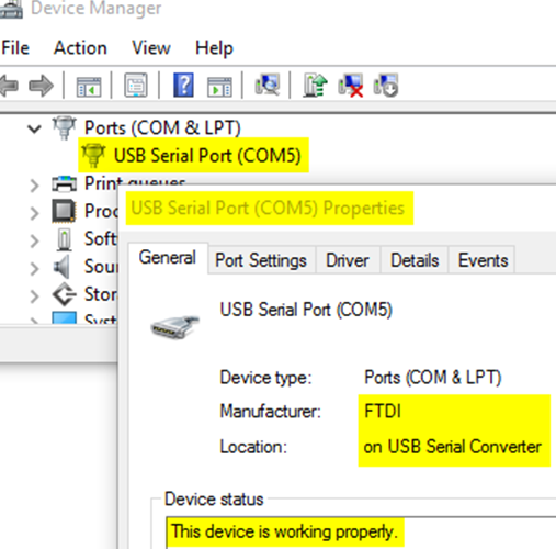 Figure 15. Windows Device Manager COM Ports
 -
Start the CANlink® wireless 3000 Configurator on the PC.
-
Choose OPTIONS → CONNECTION SETTINGS.. from the menu.
✓ This opens the window CONNECTION SETTINGS.
-
In the SETTINGS: select the device’s COM port from the dropdown list.
-
Click the CLOSE button to close the CONNECTION SETTINGS window.
-
Choose DEVICE → CONNECT from the menu.
✓ The connection is established.
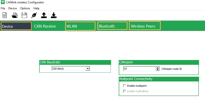
5.3. Configuring the Device
The following chapters will give an overview of the required configuration settings for the several options which are mentioned in the Use Cases Overview.
The settings for each section, the tabs Device, WLAN, Bluetooth and Wireless Peers are listed in separate tables.
|
In this document, only the basic settings for the individual connection methods are listed. Further details on how to configure the CANlink® wireless 3000, can be found in the CANlink® wireless Configurator Manual at the Document Library. |
|
5.3.1. CAN – Mobile Device / PC Interface P2P Bluetooth
Device
| Section | Parameter | Setting |
|---|---|---|
Multipoint Connectivity |
Enable multipoint |
|
Multipoint Connectivity |
Enable multitalking |
|
WLAN
| Section | Parameter | Setting |
|---|---|---|
WLAN Settings |
Enable |
|
Bluetooth
| Section | Parameter | Setting |
|---|---|---|
Device Configuration |
Enable |
|
Device Configuration |
Device name |
Enter a unique name for the Bluetooth device |
Device Configuration |
Discoverable |
|
Device Configuration |
Pairable |
|
Security Settings |
Security mode Bluetooth 2.1 |
|
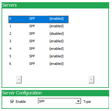
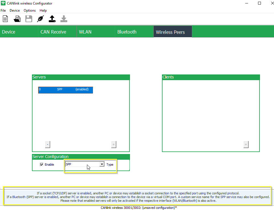
Wireless Peers
| Section | Parameter | Setting |
|---|---|---|
Servers |
SPP |
|
Server Configuration |
Enable |
|
Server Configuration |
Type |
|
Clients |
- |
- |
5.3.2. CAN – Mobile Device / PC Interface P2P WLAN Access Point mode
Device
| Section | Parameter | Setting |
|---|---|---|
Multipoint Connectivity |
Enable multipoint |
|
Multipoint Connectivity |
Enable multitalking |
|
WLAN
| Section | Parameter | Setting |
|---|---|---|
WLAN Settings |
Enable |
|
WLAN Settings |
Operating Mode |
|
WLAN Settings |
SSID |
Enter user friendly name of the WLAN Access Point (e.g. |
WLAN Settings |
Authentication Type |
Select the authentication type (e.g. |
WLAN Settings |
Authentication Key |
Enter secure authentication key (minimum key length: 8 digits). |
IP Settings |
DHCP Mode |
|
IP Settings |
Host name |
Enter a name for the device within the WLAN. |
IP Settings |
IP address |
|
IP Settings |
Network mask |
|
IP Settings |
Gateway address |
|
IP Settings |
Primary DNS Server |
|
IP Settings |
Secondary DNS Server |
|
Bluetooth
| Section | Parameter | Setting |
|---|---|---|
Device Configuration |
Enable |
|
Wireless Peers
| Section | Parameter | Setting |
|---|---|---|
Servers |
TCP |
|
Server Configuration |
Enable |
|
Server Configuration |
Type |
|
Server Configuration |
Type |
|
Clients |
- |
- |
5.3.3. CAN – Mobile Device / PC Interface P2P WLAN Infrastructure mode
Device
| Section | Parameter | Setting |
|---|---|---|
Multipoint Connectivity |
Enable multipoint |
|
Multipoint Connectivity |
Enable multitalking |
|
WLAN
| Section | Parameter | Setting |
|---|---|---|
WLAN Settings |
Enable |
|
WLAN Settings |
Operating Mode |
|
WLAN Settings |
SSID |
Enter the service set identifier (SSID) of the used WLAN network |
WLAN Settings |
Authentication Type |
Select according to settings of the used WLAN network |
WLAN Settings |
Authentication Key |
Set according to settings of the used WLAN network |
IP Settings |
DHCP Mode |
|
IP Settings |
Host name |
Enter a name for the device within the WLAN. |
Bluetooth
| Section | Parameter | Setting |
|---|---|---|
Device Configuration |
Enable |
|
Wireless Peers
| Section | Parameter | Setting |
|---|---|---|
Servers |
TCP |
|
Server Configuration |
Enable |
|
Server Configuration |
Type |
|
Server Configuration |
Type |
|
Clients |
- |
- |
5.3.4. CAN – CAN Bridge P2P Bluetooth Classic
CAN – CAN Bridge P2P Bluetooth Classic - SPP Server
Device
| Section | Parameter | Setting |
|---|---|---|
Multipoint Connectivity |
Enable multipoint |
|
Multipoint Connectivity |
Enable multitalking |
|
WLAN
| Section | Parameter | Setting |
|---|---|---|
WLAN Settings |
Enable |
|
Bluetooth
| Section | Parameter | Setting |
|---|---|---|
Device Configuration |
Enable |
|
Device Configuration |
Device name |
Enter a unique name for the Bluetooth device |
Device Configuration |
Discoverable |
|
Device Configuration |
Pairable |
|
Security Settings |
Security mode Bluetooth 2.1 |
|
Wireless Peers
| Section | Parameter | Setting |
|---|---|---|
Servers |
SPP |
|
Server Configuration |
Enable |
|
Server Configuration |
Type |
|
Clients |
- |
- |
CAN – CAN Bridge P2P Bluetooth Classic - SPP Client
Device
| Section | Parameter | Setting |
|---|---|---|
Multipoint Connectivity |
Enable multipoint |
|
Multipoint Connectivity |
Enable multitalking |
|
WLAN
| Section | Parameter | Setting |
|---|---|---|
WLAN Settings |
Enable |
|
Bluetooth
| Section | Parameter | Setting |
|---|---|---|
Device Configuration |
Enable |
|
Device Configuration |
Device name |
Enter a unique name for the Bluetooth device |
Device Configuration |
Discoverable |
|
Device Configuration |
Pairable |
|
Security Settings |
Security mode Bluetooth 2.1 |
|
Wireless Peers
| Section | Parameter | Setting |
|---|---|---|
Servers |
- |
Leave the server settings empty. |
Clients |
SPP |
|
Client Configuration |
Type |
|
Client Configuration |
Enable |
|
Client Configuration |
MAC address |
Enter BT MAC address of the device which is to be used as SPP Server module |
5.3.5. CAN – CAN Bridge P2P Bluetooth Classic - exchangeable peers
CAN – CAN Bridge P2P Bluetooth Classic - exchangeable peers - SPP Server
Device
| Section | Parameter | Setting |
|---|---|---|
Multipoint Connectivity |
Enable multipoint |
|
Multipoint Connectivity |
Enable multitalking |
|
WLAN
| Section | Parameter | Setting |
|---|---|---|
WLAN Settings |
Enable |
|
Bluetooth
| Section | Parameter | Setting |
|---|---|---|
Device Configuration |
Enable |
|
Device Configuration |
Device name |
|
Device Configuration |
Discoverable |
|
Device Configuration |
Pairable |
|
Security Settings |
Security mode Bluetooth 2.1 |
|
Wireless Peers
| Section | Parameter | Setting |
|---|---|---|
Servers |
SPP |
|
Server Configuration |
Enable |
|
Server Configuration |
Type |
|
Clients |
- |
- |
CAN – CAN Bridge P2P Bluetooth Classic - exchangeable peers - SPP Client
Device
| Section | Parameter | Setting |
|---|---|---|
Multipoint Connectivity |
Enable multipoint |
|
Multipoint Connectivity |
Enable multitalking |
|
WLAN
| Section | Parameter | Setting |
|---|---|---|
WLAN Settings |
Enable |
|
Bluetooth
| Section | Parameter | Setting |
|---|---|---|
Device Configuration |
Enable |
|
Device Configuration |
Device name |
Enter a unique name for the Bluetooth device |
Device Configuration |
Discoverable |
|
Device Configuration |
Pairable |
|
Security Settings |
Security mode Bluetooth 2.1 |
|
Wireless Peers
| Section | Parameter | Setting |
|---|---|---|
Servers |
- |
Leave the server settings empty. |
Clients |
SPP |
|
Client Configuration |
Type |
|
Client Configuration |
Enable |
|
Client Configuration |
Mode |
|
Client Configuration |
Group name |
Enter the group name from the device which is to be used as SPP Server module. (example: |
5.3.6. CAN – CAN Bridge P2P WLAN Access Point mode
CAN – CAN Bridge P2P WLAN Access Point mode - TCP Server
Device
| Section | Parameter | Setting |
|---|---|---|
Multipoint Connectivity |
Enable multipoint |
|
Multipoint Connectivity |
Enable multitalking |
|
WLAN
| Section | Parameter | Setting |
|---|---|---|
WLAN Settings |
Enable |
|
WLAN Settings |
Operating Mode |
|
WLAN Settings |
SSID |
Enter user friendly name of the WLAN Access Point (e.g. |
WLAN Settings |
Authentication Type |
Select the authentication type (e.g. |
WLAN Settings |
Authentication Key |
Enter a secure authentication key (minimum key length: 8 digits). |
IP Settings |
DHCP Mode |
|
IP Settings |
Host name |
Enter a name for the device within the WLAN. |
IP Settings |
IP address |
|
IP Settings |
Network mask |
|
IP Settings |
Gateway address |
|
IP Settings |
Primary DNS Server |
|
IP Settings |
Secondary DNS Server |
|
Bluetooth
| Section | Parameter | Setting |
|---|---|---|
Device Configuration |
Enable |
|
Wireless Peers
| Section | Parameter | Setting |
|---|---|---|
Servers |
TCP |
|
Server Configuration |
Enable |
|
Server Configuration |
Type |
|
Server Configuration |
Type |
|
Clients |
- |
- |
CAN – CAN Bridge P2P WLAN Access Point mode - TCP Client
Device
| Section | Parameter | Setting |
|---|---|---|
Multipoint Connectivity |
Enable multipoint |
|
Multipoint Connectivity |
Enable multitalking |
|
WLAN
| Section | Parameter | Setting |
|---|---|---|
WLAN Settings |
Enable |
|
WLAN Settings |
Operating Mode |
|
WLAN Settings |
SSID |
Set the same SSID like for the WLAN AP (TCP Server) |
WLAN Settings |
Authentication Type |
According to the settings of the WLAN AP (TCP Server) |
WLAN Settings |
Authentication Key |
According to the settings of the WLAN AP (TCP Server) |
IP Settings |
DHCP Mode |
|
IP Settings |
Host name |
Enter a name for the device within the WLAN. |
Bluetooth
| Section | Parameter | Setting |
|---|---|---|
Device Configuration |
Enable |
|
Wireless Peers
| Section | Parameter | Setting |
|---|---|---|
Servers |
- |
Leave the server settings empty. |
Clients |
TCP |
|
Client Configuration |
Type |
|
Client Configuration |
Enable |
|
Client Configuration |
Address |
Static IP address of the device which is to be used as Access Point. |
Client Configuration |
Port |
|
5.3.7. CAN – CAN Bridge Multipoint Bluetooth Classic
In the following configuration example, a multipoint configuration in Bluetooth mode is shown.
|
|
CAN – CAN Bridge Multipoint Bluetooth Classic - SPP Server
Device
| Section | Parameter | Setting |
|---|---|---|
Multipoint Connectivity |
Enable multipoint |
|
Multipoint Connectivity |
Enable multitalking |
|
|
WLAN
| Section | Parameter | Setting |
|---|---|---|
WLAN Settings |
Enable |
|
Bluetooth
| Section | Parameter | Setting |
|---|---|---|
Device Configuration |
Enable |
|
Device Configuration |
Device name |
Enter a unique name for the Bluetooth device |
Device Configuration |
Discoverable |
|
Device Configuration |
Pairable |
|
Security Settings |
Security mode Bluetooth 2.1 |
|
Wireless Peers
| Section | Parameter | Setting |
|---|---|---|
Servers |
SPP |
|
Server Configuration |
Enable |
|
Server Configuration |
Type |
|
Clients |
- |
Leave the clients section empty. |
CAN – CAN Bridge Multipoint Bluetooth Classic - SPP Clients
|
Device
| Section | Parameter | Setting |
|---|---|---|
Multipoint Connectivity |
Enable multipoint |
|
Multipoint Connectivity |
Enable multitalking |
|
WLAN
| Section | Parameter | Setting |
|---|---|---|
WLAN Settings |
Enable |
|
Bluetooth
| Section | Parameter | Setting |
|---|---|---|
Device Configuration |
Enable |
|
Device Configuration |
Device name |
Enter a unique name for the Bluetooth device |
Device Configuration |
Discoverable |
|
Device Configuration |
Pairable |
|
Security Settings |
Security mode Bluetooth 2.1 |
|
Wireless Peers
| Section | Parameter | Setting |
|---|---|---|
Servers |
- |
Leave the server settings empty. |
Clients |
SPP |
|
Client Configuration |
Type |
|
Client Configuration |
Enable |
|
Client Configuration |
MAC address |
Enter BT MAC address from the device which is to be used as Mutltipoint SPP Server module |
5.4. Hardware installation
This chapter provides important notes regarding the hardware setup.
|
|
|
5.4.1. Mounting the Device
Below you will find instructions on how to mount the device.
Directly affix the device with two socket head bolts of type M4 with hexagon socket/ DIN 912 - ISO 4762 which are at least 25 mm long. Tighten the bolts with a torque of M = 0.9 … 1.1 Nm. In order to secure the bolts, we recommend using two washers of the type Tooth lock washer for M4 according to DIN 6797 - external teeth.
|
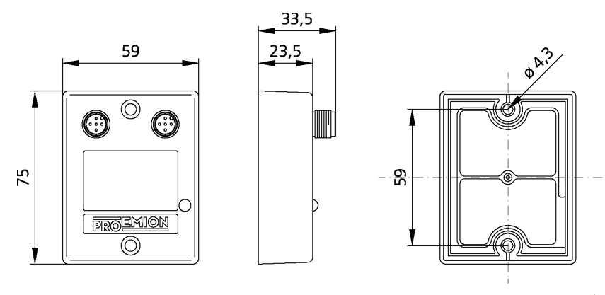
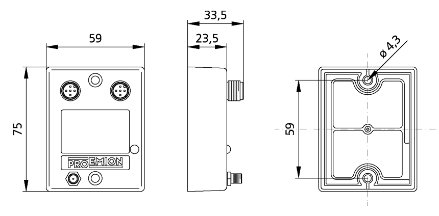
To get the distance of the mounting holes, please refer to chapter Technical Drawings.

| # | Description |
|---|---|
1 |
Socket head bolt size M4 with hexagon socket / DIN 912 - ISO 4762, length at least 25 mm |
2 |
Tooth lock washer for M4 according to DIN 6797 - external teeth |
3 |
CANlink® wireless 3000 |
|
5.4.2. Internal Antenna
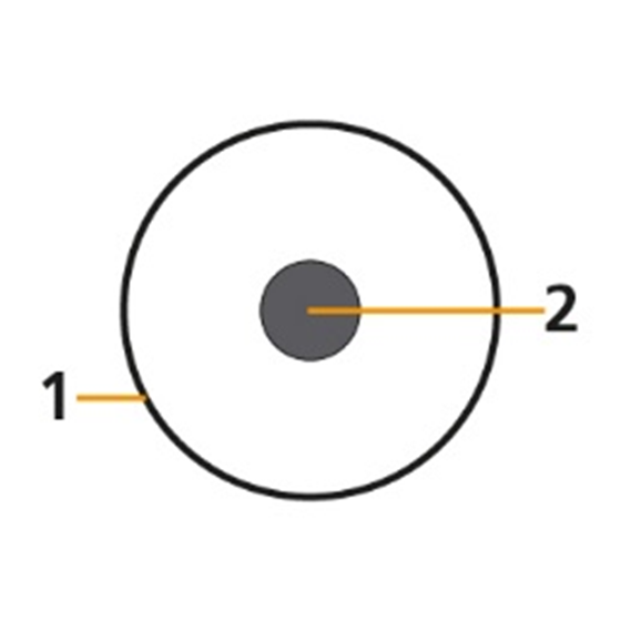
The internal antenna of the CANlink wireless variant 3001 is located on the top side of the main PCB, therefore it is recommended to mount the device in such a way that the top side also has the best possible alignment and free sight to its peer. Please refer to figure Antenna positioning.
When using a setup with external antennas, it is also mandatory that the antennas have free sight to each other and are not blocked by any housing materials or other signal dampening materials.
|
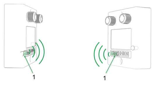
| # | Description |
|---|---|
1 |
Position of internal antenna |
5.4.3. External Antenna
Below you will find some important notes regarding the antenna setup.
|
6. Operation
This chapter contains information on operating the device and the CANlink® wireless 3000 Configurator software.
6.1. CANlink® wireless 3000 Configurator
Configure the device with the CANlink® wireless 3000 Configurator software. To modify the configuration of your device, first connect it to the PC. See chapter Connection with a PC via RS232.
|
In this document, only the basic settings for the individual connection methods are listed in chapter Configuring the Device. Further details on how to configure the CANlink® wireless 3000 and additional information regarding the advanced options, can be found in the CANlink® wireless Configurator Manual at the Document Library. |
|
The software can be downloaded from our Download Center at the Document Library |
|
|
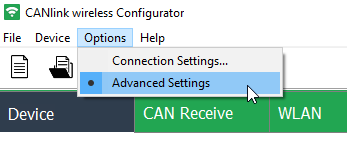
6.1.1. Enable Advanced Settings
The CANlink® wireless 3000 Configurator software starts by default with the basic configuration options. This allows the user to focus onto the essential settings to get a new device configured. In some cases it may be necessary to enable the Advanced Settings, therefore please click on Options → Advanced Settings.
6.2. CAN functions
This chapter provides information on how to use and configure CAN functions.
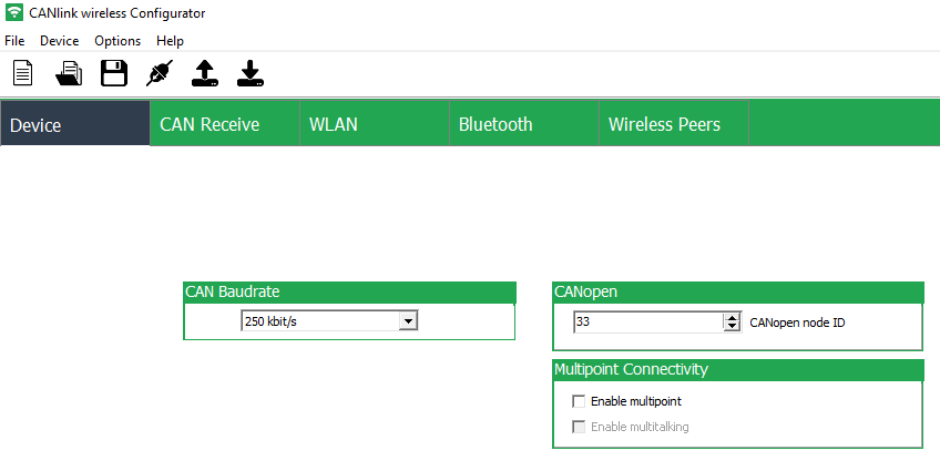
6.2.1. CAN / CANopen
The CANlink wireless supports the transmission of pure CAN messages to another device. No direct protocol interpretation is configured in the firmware. This makes it possible to use the device for different applications with various CAN transport protocols. The protocol logic must be implemented in the other device (e.g. in the PC software, for example CANopen Magic).
6.2.2. Enabling the CANopen Stack
The CANopen stack prevents the transmission of some CAN messages such as CANopen RX SDOs, TX SDOs, and emergency messages. These messages are received by the device’s CANopen stack and processed to the radio Interface without being forwarded on. It is possible to configure the device for connection control via CANopen. In that case, the device does not transmit messages with certain CAN identifiers. The following table shows messages that are used by the device but not transmitted when the CANopen stack is enabled.
| Type | CAN Identifier | Default configuration (Node ID 33) |
|---|---|---|
TX SDO 1 |
|
|
RX SDO 1 |
|
|
Heartbeat/Boot-Up |
|
|
NMT |
|
|
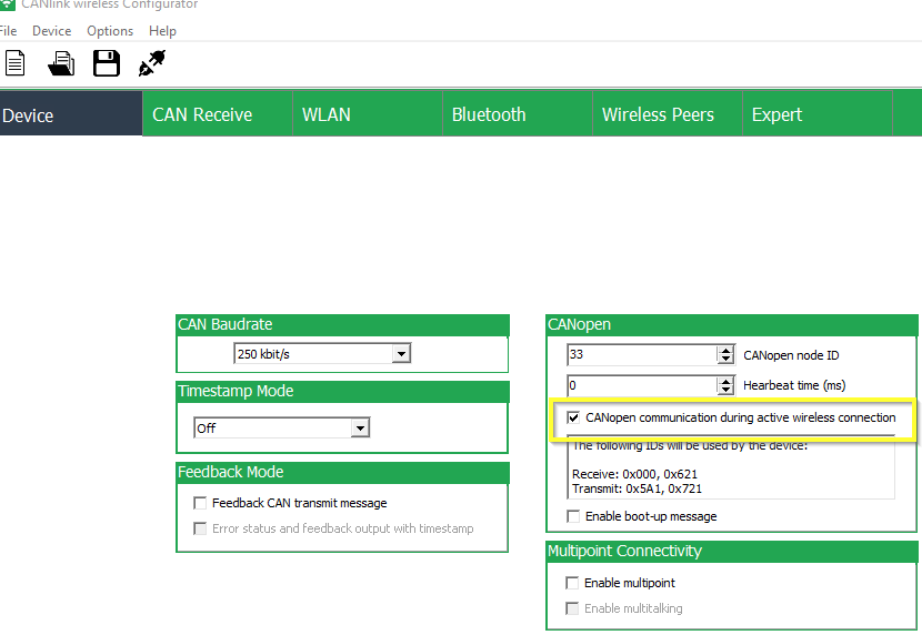
To enable the CANopen stack, the Advanced Settings must be activated within the CANlink® wireless 3000 Configurator first. Refer to Enable Advanced Settings.
In the CANopen field of the Device tab enable the checkbox CANopen communication during active wireless connection.
|
6.2.3. Boot-Up message
Directly after startup, the device optionally transmits a CANopen boot-up message with its own node ID.
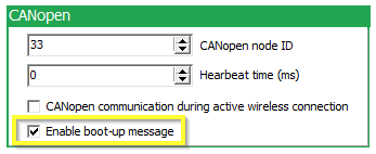
To enable the Boot-Up message, the Advanced Settings must be activated within the CANlink® wireless 3000 Configurator first. Refer to Enable Advanced Settings.
In the CANopen field of the Device tab enable the checkbox Enable boot-up message.
|
6.2.4. Filter received CAN messages
The device offers the option of configuring message filters. This allows you to reduce the transmission load and ensure that the CAN bus only transmits certain CAN messages.
In the CAN Receive tab of the CANlink® wireless 3000 Configurator you can set filter masks and activate or deactivate individual bits for the comparison function of online CAN objects. You can individually filter up to 8 separate CAN identifiers with unique online CAN objects and downsample them if necessary.
A CAN message that does not match the receive filter of an online CAN object is passed on to the next active online CAN object and checked again. If the number of CAN identifiers to be filtered is less than eight, you can assign a unique CAN identifier to each online CAN object. Use the filter mask 0x7FF for 11-bit or 0x1FFFFFFF for 29-bit CAN identifiers to filter individual CAN identifiers separately.
Some examples are described in more detail below.
|
|
Filter Calculation Example 1:
CAN messages with a CAN identifier 0x123 are received. CAN messages with a different CAN identifier are filtered out and forwarded to the next online CAN object.
| Online CAN object | Binary |
|---|---|
11-bit CAN identifier (hex): |
|
Resulting Filter mask (hex) |
|
CAN messages from CAN bus |
|
Filter Calculation Example 2:
CAN messages with the CAN identifiers 0x123, 0x124, and 0x125 are transmitted. The required filter mask must be determined using an XNOR gate. Other CAN messages that comply with the filter mask (e.g. 0x120, 0x121, 0x122, etc.) are also received. CAN messages with other CAN identifiers are forwarded to the next online CAN object.
| Online CAN object | Binary |
|---|---|
11-bit CAN identifier (hex): |
|
11-bit CAN identifier (hex): |
|
11-bit CAN identifier (hex): |
|
XNOR gate for filter mask |
|
Resulting Filter mask (hex) |
|
Filter Calculation Example 3:
CAN messages with the CAN identifiers 0x123, 0x124, and 0x125, 0x621, and 0x726 are transmitted. The required filter mask must be determined using an XNOR gate. Other CAN messages that comply with the filter mask are also received. CAN messages with other CAN identifiers are not received, but forwarded to the next online CAN object.
| Online CAN object | Binary |
|---|---|
11-bit CAN identifier (hex): |
|
11-bit CAN identifier (hex): |
|
11-bit CAN identifier (hex): |
|
11-bit CAN identifier (hex): |
|
11-bit CAN identifier (hex): |
|
XNOR gate for filter mask |
|
Resulting Filter mask (hex) |
|
6.3. Firmware update
To perform a firmware update via the RS232 Interface, you need the Proemion Firmware Programmer software and a connection to a PC via the USB-RS232 converter cable (part# 257001017).
The required software can be downloaded from the Download Center at our Document Library.
|
|
Install Proemion Firmware Programmer prior to the update procedure.
-
Connect the device to the PC. See chapter Connection with a PC via RS232.
-
Start Proemion Firmware Programmer.
-
In the menu, click on File > Open.
-
Select the file (
*.FwBin) with the current firmware. -
In the dropdown list of the
Communication pathfield, select the InterfaceDirect Connection via RS232. -
Identify the device’s virtual COM port in the PC’s Device Manager.
-
Select the device’s COM port.
-
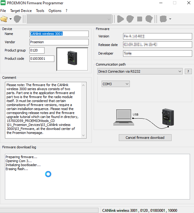
Click on the
Start firmware downloadbutton.
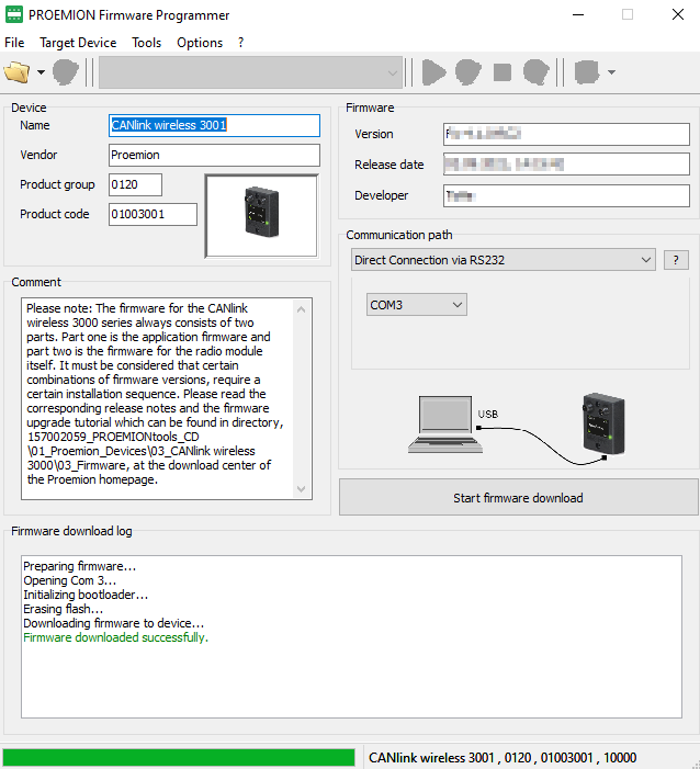
✓ During the firmware update, the LED on the device flashes green.
✓ In the field FIRMWARE DOWNLOAD LOG, the message Firmware downloaded successfully appears when the firmware update is complete.
|
6.4. Reset device (repair mode)
The repair mode resets the device to the firmware default settings.
|
-
Disconnect the device from the power supply.
-
At the RS232 Interface, Bridge TxD and RxD. For the connector assignment, see chapter RS232 connector.
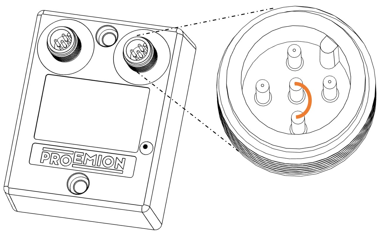 Figure 27. Device Reset - bridge of TxD and RxD
 -
Connect the power supply.
✓ The device is now in the "Repair mode ready" status. The LED flashes at a rate of 500 ms in red colour.INFORMATION
To abort the device reset , disconnect the power supply while the pins for TxD and RxD are bridged.
-
Remove the Bridge between TxD and RxD when the power supply is active.
✓ The device is in "Reset Status" and is reset to the factory settings. The LED flashes green 3 times periodically in a cycle of 200 ms and a pause of 1000 ms.
✓ After the reset to factory settings, the device goes into sleep mode. The LED blinks green in a cycle of 200 ms.
✓ The CAN bit rate is 250 kbit/s.
|
7. Troubleshooting and maintenance
This chapter contains advice on eliminating possible errors and notes on maintenance.
7.1. Troubleshooting
| Problem | Advice |
|---|---|
Device is without any function |
Check the power supply via the CAN connector |
Device does not receive CAN messages |
Check the CAN connection and the configuration of the CAN messages and filters. |
Device is stuck in sleep mode |
Check if terminal 15 is connected or VCC is connected to pin 3 of the CAN / Power connector. Use the |
LED lights up constant red |
CAN error (e.g. bus off), radio module error, voltage critical. |
LED lights up constant red after powering on |
Ensure that "Enable boot-up message" is disabled in the device configuration. |
Device does not transmit all CAN messages |
Check if the CANopen stack is enabled. Change the CAN identifiers of the affected CAN messages (RX SDOs, TX SDOs, emergency messages). |
Device does not transmit any CAN messages |
Check the CAN baud rate |
If you do not find the solution to your problem within this manual, contact the Service and Support.
The support team requires the following information in order to help you.
-
Description of the problem.
-
Serial number of the device.
-
Firmware version of the device.
-
Support archive. See chapter Create Support Archive.
-
What is the indicator LED status?
→ Is the LED lighting up in the order shown in the table?
→ Is the LED lighting up red?
→ After which status does the LED light up red?
Contact Service and Support to provide the required device information and description of the problem.
7.2. Maintenance
-
Regularly check all connectors for a firm connection.
-
Regularly check the housing for cracks or any other damages.
-
Ensure that the RS232 connector is covered with its protection cap.
7.3. Remote Bluetooth Address
The "Remote Bluetooth Address" object is used to add a "Bluetooth MAC Address" in order to make the device connect to a remote device.
In order to remove a connection to the previous remote device, use the "disconnect" command.
it is not required to delete the MAC address in order to make the device not connect to the configured address.
But in order to delete the MAC address that was configured before, you must write an empty string (\0) to the CANopen object.
8. Packaging and Transport
This chapter contains information on packing and transportation.
|
9. Disposal
This chapter contains information on correct disposal.
|

10. Annex
This chapter contains technical data and certificates.
10.1. Technical Drawings
|
10.2. Technical Data
This chapter contains information on the technical data of the device.
10.2.1. Mechanical
| Parameter | Value |
|---|---|
Dimensions width/height/depth [ |
|
Color |
Black |
Protection class |
|
Temperature range |
-30 °C − +75 °C / -22 °F − +167 °F |
Weight |
|
Standard housing material |
|
10.2.2. Electrical
| Parameter | Value |
|---|---|
Supply voltage range terminal 30 DC |
|
Power consumption, at 24 V |
|
Power consumption in sleep mode |
|
Average power consumption |
|
Controller |
|
Memory expansion Program Flash |
|
Data Flash memory expansion |
|
Memory expansion SRAM |
|
LEDs |
|
10.2.3. Interfaces
|
| Parameter | Value |
|---|---|
CAN (number, ISO) |
|
CAN specification |
|
Max. CAN baud rate |
|
Operating modes |
|
RS232 |
For firmware update and configuration |
Bluetooth Standard |
|
WLAN Standard |
|
WLAN encryption |
|
WLAN transmission rate |
|
RF transmission power |
Bluetooth 2.4 GHz |
Data transfer rate |
Bluetooth single point: |
Average latency period for transmission of a single CAN message |
Bluetooth Bridge Single Point: |
Maximum Range |
Bluetooth, Single Point Mode: |
Antenna Connector |
3001: internal antenna |
Buffer sizes: |
CAN receive buffer: |
10.2.4. CAN-WLAN Interface
In operation as a CAN-WLAN Interface, CAN data is transmitted wireless to other WLAN-capable devices such as PCs, smartphones or tablets.
The CAN-WLAN Interface features two operating modes: infrastructure mode and access point mode. In infrastructure mode, data transmission takes place via one or more access points. In access point mode, the CANlink® wireless 3000 additionally provides a WLAN access point function.
WLAN ENCRYPTION
| Name | Authentication | Data protection |
|---|---|---|
None |
No |
No |
WEP64 |
Yes |
according to WEP64 |
WEP128 |
Yes |
according to WEP128 |
WPA/WPA2 Mixed Mode |
Yes |
according to WPA or WPA2 |
PEAP |
Yes |
via RADIUS server |
WLAN FREQUENCIES AND CHANNELS
The device’s radio module features automatic domain recognition and supports the following regulatory domains: WORLD, ETSI, FCC. If it does not detect ETSI or FCC, the radio module uses WORLD as the default.
| Name | Band | TX Channel |
|---|---|---|
World |
|
|
ETSI |
|
|
FCC |
|
|
|
10.3. Certification and Qualification
The device has been certified and qualified according to the valid standards and regulations.
For more information on the corresponding approval tests, please contact the Proemion support.
|
Proemion GmbH hereby declares that the CANlink® wireless 3000 communication system complies with the provisions in Directive 2014/53/EU.
|
The full text of the declaration of conformity is available at our website Declaration of Conformity. |
E1
ECE Regulation No. 10 (version 6)
Approval number: 10 R-067908
Version: 11.0.988