1. Introduction
1.1. Legal notices
All brands and trademarks named in this document and possibly protected by third-party rights are subject without limitation to the terms of the valid trademark law and intellectual property rights of their respective registered owner.
You can find a list of the free-source and open-source software as well as copyright notes, license texts and, if applicable, the relevant source code on our website under the link: Free & Open Source Software
Observe all local and regional laws and provisions as well as the safety instructions contained in this document.
1.2. Contact details
Proemion GmbH
Donaustr. 14
36043 Fulda, Germany
Phone: +49 661 9490-0
Fax: +49 661 9490-111
info@proemion.com
Proemion Corp.
US Subsidiary
241 Taylor St., Suite 301
Dayton, Ohio 45402, USA
Phone: +1 937 558 2211
Fax: +1 937 641 8787
info-dayton@proemion.com
Proemion Ltd.
373 Gangnam-daero Seocho-gu
Seoul, 06621, South Korea
Phone: +82 2 6080 9490
Fax: +82 504 484 9490
info-seoul@proemion.com
Website: Proemion
1.3. Warranty and liability
Proemion assumes no liability for defects caused by normal wear, external influence, and errors of installation, operating, or maintenance.
This also applies if the customer or third parties modify the devices, any accessories, or the software without the approval of Proemion.
1.4. About this manual
This document is part of the product and provides important information on the intended use, safety, installation, and operation of the devices described below.
The document is intended for qualified technicians and electricians with advanced knowledge in electrical engineering and field bus systems, allowing them to estimate the risks and hazards of operating the device and to integrate it into systems with components of other manufacturers.
1.5. About the software
The CANlink® wireless Configurator is a software tool that allows the adaption of objects of the CANopen dictionary for the CANlink® wireless 3000 via the GUI in order to configure this devices in the desired state, i.e CAN-CAN bridge or CAN-PC connection, etc.
The CANlink® wireless Configurator can perform the following main features:
-
Create the configuration for the device.
-
Create a support archive.
-
Read out and write configuration files.
-
Reset device.
| Additional hints for individual configuration options can be found within the tooltips when hovering a certain field in the GUI. |
|
Previously, the CANlink wireless 4000 could also be managed by the CANlink® wireless Configurator. This support has been removed, and now the CANlink wireless 4000 is configured by the Proemion Configurator software. More information can be found in Configurator Installation. --- <<< :leveloffset: +1 |
2. Service and Support
The latest versions of the drivers, software, firmware, and documentation are available in our Document Library.
Do you need help or want to report a bug?
Visit Proemion for more information, or raise a ticket at Support.
2.1. Firmware Updates and Support
|
2.2. Create Support Archive
The CANlink® wireless Configurator software incorporates the option to create a backup of the installed device configuration and static device parameters.
This function can be used to save the original configuration and device information such as software version, WiFi and Bluetooth MAC address, etc.
In the event of a malfunction, the support archive should be attached to the support request.
| To keep a backup of the latest configuration status, it is always recommended to create a support archive before installing a customized configuration. |
-
Connect the device to the PC.
See Connection with a PC via RS232. -
Choose DEVICE → READ DATA FROM THE DEVICE from the menu.
✓ The configuration from the device is loaded.
-
Choose HELP → CREATE SUPPORT ARCHIVE from the menu.
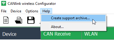 Figure 1. Create Support Archive menu
✓ This opens Windows File Explorer.
-
Enter an explicit file name for the backup file of the original device configuration.
-
Click the SAVE button.
✓ This saves a backup file of the original device configuration config.clk and also a text file details.txt with the most important device information into a *.zip archive:
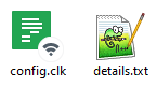
Click to view the sample device information file:
Details
Example of device information file (details.txt):
Date and time: 16.03.2022 07:41:50

APPLICATION
-----------
Name: CANlink wireless Configurator
Version: 4.1.0.1

DEVICE
------
ID string: CANlink wireless 3xxx 1.x.x 2.0 01003001 <RS>
Serial number: 2148007
Product code: 1003001
Vendor ID: 524D
Product group: 120
UNIX time of manufacture: 06.12.2021 06:53:19 UTC
WLAN FW version: 1610.2.4.0.0.36
WLAN MAC address: 80:C9:55:A1:FA:2C
Bluetooth MAC address: 80:C9:55:D3:29:35
3. Getting Started
This chapter describes the first steps in order to install the CANlink® wireless Configurator, to connect the device with the PC/software and read out and write or adapt the configuration.
3.1. Install Software
The CANlink® wireless Configurator can be downloaded at Download Center > 03_Proemion Tools Software > 01_Software > 09_PROEMION CANlink wireless Configurator.
After the installation of the CANlink® wireless Configurator, you can connect your device with the software, see next section.
3.2. Connect Device with CANlink® wireless Configurator
Prerequisites
In order to connect the devices with the CANlink® wireless Configurator, you must connect them with PC beforehand, instructions can be found in the Connection with a PC via RS232.
After connecting the devices with the PC, you can connect them with the CANlink® wireless Configurator:
-
In the menu Options > Communication Settings you can then select the serial port for the Bluetooth connection.
-
To finally connect, select Device > Connect or
 .
.
✓ The device is now connected to the CANlink® wireless Configurator.
You can now Read Data from Device or Create new Configuration.
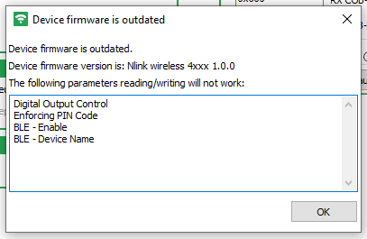
In case the device firmware is outdated, a dialog may be displayed upon connecting the device, see below.
To update the device firmware, read Firmware Update.
To disconnect the device, select Device > Disconnect or select ![]() .
.
3.3. Load/Open Configuration
In order to use a local configuration file from your computer in the CANlink® wireless Configurator, in the menu bar, select File > Load Configuration or select  .
.
| When selecting Read Data from Device, it overwrites the loaded configuration. |
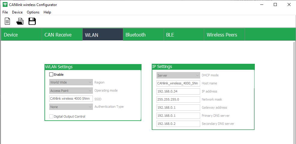
4. Configure Device
The CANlink® wireless Configurator allows to configure the device via different settings.
These settings are sorted in the following tabs.
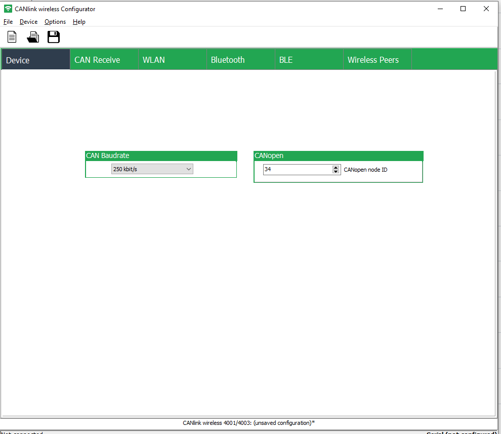
4.1. Device
The Device tab is used to configure the CAN Baudrate and CANopen settings.
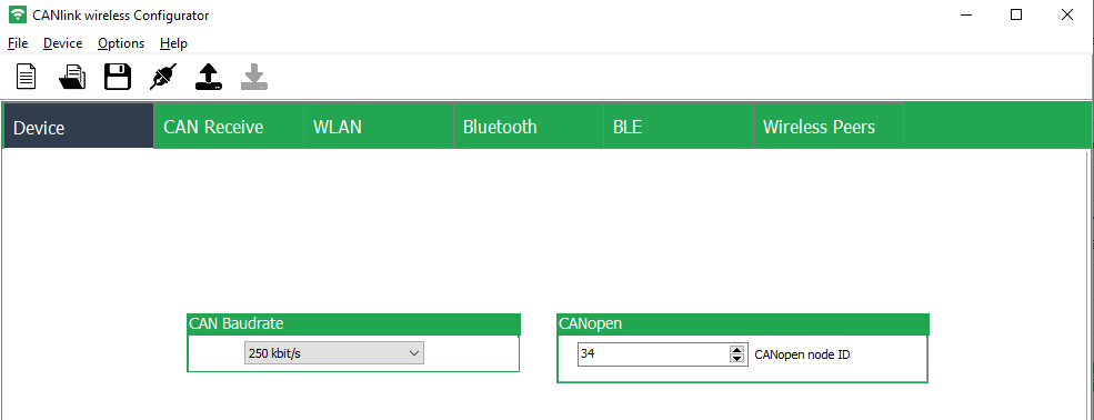
4.1.1. CAN Baudrate
The CAN baud rate is the speed/rate at which the data is transmitted on the CAN bus.
When integrating the device into the desired CAN network, it must be ensured that the configured CAN baud rate is matching the CAN baud rate of the local CAN bus, otherwise the device changes to error mode.
|
Devices with installed factory configuration have a default CAN baud rate of 250 kbit/s. After a reset to factory settings, the CAN baud rate is set back to 250 kbit/s. |
4.1.2. CANopen
The CANopen node ID (address) of a CANopen device on the local CAN bus must be unique and within the range from 1 to 127.
| With the factory configuration installed as well as after a device reset, the default CANopen node ID is 33 (decimal). |
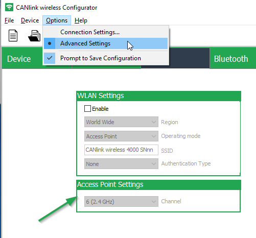
4.1.3. Advanced Settings
Select Options > Advanced Settings to configure the following fields.
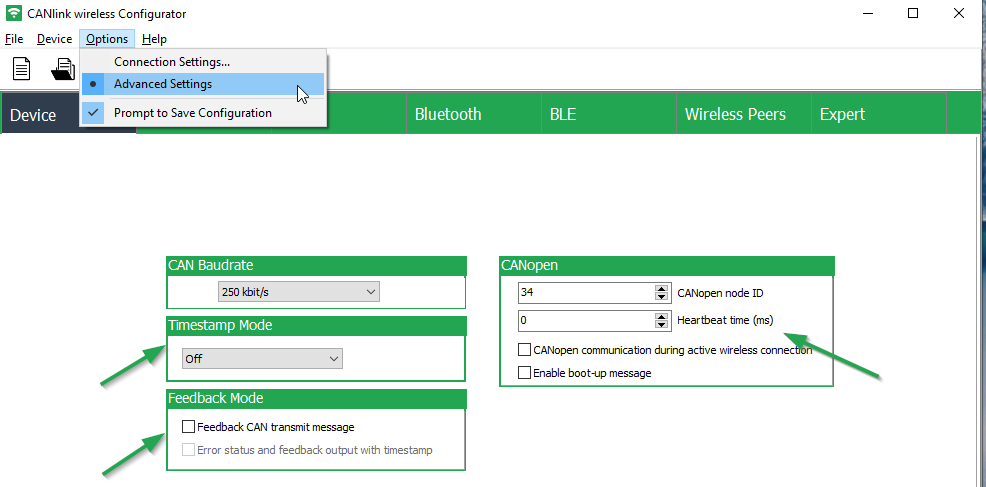
Hover over the fields and check marks to find the tool tips.
-
Timestamp Mode
-
Feedback Mode
-
Feedback CAN transmit message: Note that when activating this option, it may lead to a significant performance decrease in a CAN-CAN bridge setup.
-
-
CANopen
-
Heartbeat time
-
CANopen communication during active wireless connection:
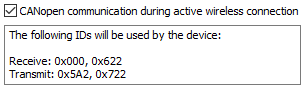 Figure 6. "CANopen communication during active wireless connection" checkbox
To enable the CANopen stack and sending messages.
The SDO server is displayed as 0x600 with the Node ID as hexadecimal22.
For more details, read Enabling the CANopen Stack and other sections of the chapter "CAN functions" in the CANlink wireless 4000 Device Manual CANlink® wireless 4000 Device Manual. -
Enable boot-up message
-
4.2. CAN Receive
The CAN Receive tab shows the active/inactive receive objects for 11- and 29-bit CAN message identifiers and allows filtering of selected CAN messages to improve the message throughput.
The default configuration for the CAN Receive settings already include active receive objects with open filter masks for all 11-bit and 29-bit CAN message identifiers.
With this setting, all CAN messages are transmitted.
If the CANlink wireless device is connected to a CAN bus with high bus load, filtering of specific messages is recommended.
For a detailed description and examples, read Filter received CAN messages in the CANlink® wireless 4000 Device Manual Device Manual.
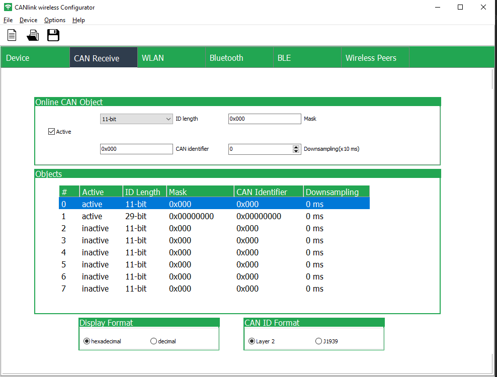
4.2.1. Configuration
In the Online CAN Object section, you can configure following fields:
-
ID length: is used to select 11-bit or extended 29-bit CAN message identifier.
-
Mask: is used to set a filter mask for single messages or specific groups of messages.
This makes it possible to only transfer the application-relevant messages. -
CAN identifier: is used to filter by CAN IDs (in the format hex (0x) or decimal - the format can be changed in the field Display Format)
-
Downsampling: is used to limit the transmission rate in case of a high message frequency.
| Downsampling is only recommended for filtering of single messages. |
| The CAN messages are transmitted via block transfer. Depending on the message load and the radio technology used, there are unavoidable latency times. Please test your configuration and application under real operating conditions. |
4.4. Bluetooth
In the tab Bluetooth you find the Device Configuration and Security Settings sections to make the changes as described below.
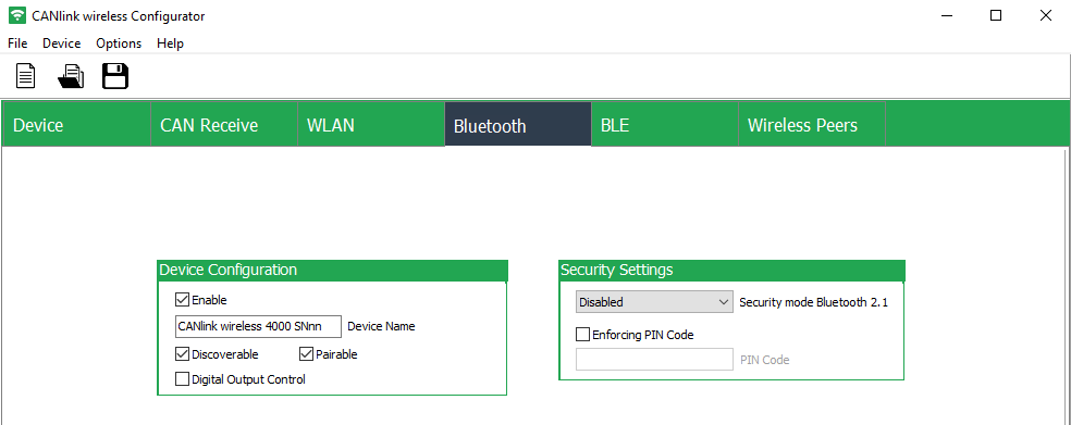
4.4.1. Configuration
-
Enable: Enable Bluetooth.
-
Device Name: Change the device name here.
The device name may have 4 to 29 characters. -
Discoverable and Pairable: Make the device discoverable und pairable (requirement for Bluetooth).
-
Digital Output Control: When this option is enabled, the Digital Output is switched High when a Bluetooth connection has been established.
This may be used to signal or switch other systems that depend on a valid Bluetooth connection. -
Enforcing PIN Code: When entering a Bluetooth PIN code for the CAN-PC connection, the length may have a maximum size of 15 characters.
When the PIN code has been enforced, the password is required:-
For the device.
Here, the PIN must be entered in this PIN code field. -
For the device to be paired, e.g. PC.
Here, a window will be displayed for entering the PIN and establishing the connection.
-
4.5. Wireless Peers
The Wireless Peers tab is used to set up a point-to-point (P2P) (bridge) connection, i.e. connecting a device to another, to enable the manipulation of CAN data or to share CAN data between 2 physically separated networks.
Therefore, both the server and client must be configured.
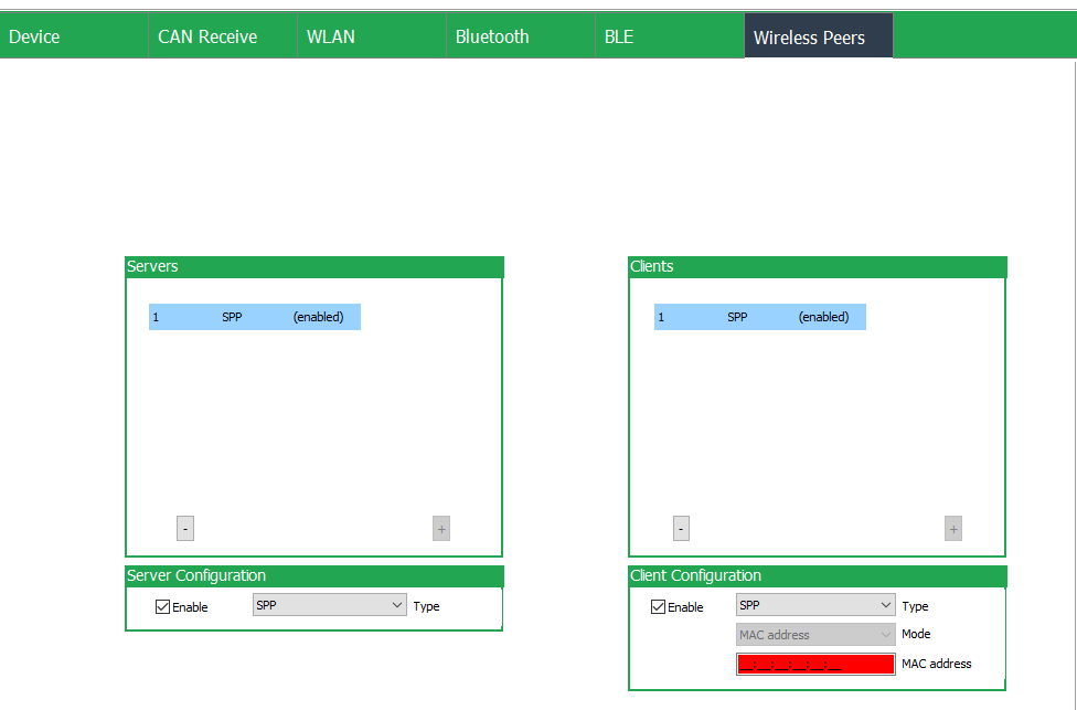
4.6. Add Server/Client
-
In Server Configuration, select the desired Type, e.g. SPP.
-
Make sure the Server Configuration is enabled.
-
In Client Configuration, select the desired Type, e.g. SPP.
-
Make sure the Client Configuration is enabled.
Consider also that disabled Servers and Clients will not be written/read to/from the device.
5. How to…
5.1. Read Data from Device
To read data from the device, select Device > Read Data from the Device or select ![]() .
.
✓ The configuration is then loaded in the CANlink® wireless Configurator, i.e. the configuration are filled out accordingly in the tabs.
|
By reading the data, it may overwrite the currently loaded configuration. A warning will be displayed. |
5.2. Write Configuration to Device
To apply the changes in the configuration to the device, in the menu bar, select Device > Write Data to the Device or select ![]() .
.
When the write-data was successful, the message "Wrote data to device" is displayed briefly.
5.3. Create new Configuration
The CANlink wireless configuration file format is .clk.
To start with a blank configuration file, in the menu bar, select File > New Configuration or select  .
.
To use an existing configuration file, you can Load/Open Configuration.
5.4. Reset Device
In the menu bar, go to Device > Reset Device to Factory Settings.
The existing configuration is then overridden with the factory settings of the CANlink® wireless Configurator.
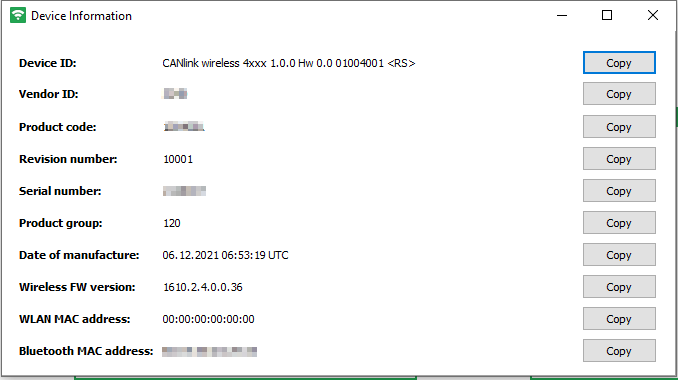
5.5. Get Device Information
To view more information, select Device > Device Information.
A dialog with information about Device ID, Serial number, Bluetooth MAC address is displayed.
Read also how to use the device information for the Support.
Version: 11.0.988