1. Introduction
The CANlink wireless 4000 device is a CAN to wireless gateway – used for bridging physically separate CAN networks together using a local wireless connection.
The CANlink wireless 4000 is a simple device that extends a CAN bus to a locally-connected peer over WiFi, Bluetooth or BLE.
Bi-directional communication can be established with another CANlink wireless 4000, a laptop or mobile device for local machine service and diagnostics.
Using a published protocol Byte Command Manual, customers can create their own applications on various platforms and devices that can wirelessly send and receive CAN data with the machine via the CANlink wireless 4000.
More than one CANlink wireless 4000 can be connected together, logically bridging several local CAN buses together.
The CANlink wireless 4000 can easily be configured using either our GUI application, or can be set up with standard CANopen tools.
2. Key Features
2.1. Wireless bridging
Wireless connection to another CANlink wireless device or connected computer.
Supported interfaces are WiFi, Bluetooth and BLE.
2.2. MultiPoint mode
A CANlink wireless 4000 acts as receiver of data from multiple other CANlink wireless 4000 devices (maximum of 7) and transmits it onto the CAN bus it is connected to.
This process operates in both directions, where CAN data is sent to connected CLW devices.
2.3. MultiTalk mode
An extension of MultiPoint mode, which also sends all received messages to all connected CANlink wireless 4000 devices. This means all connected CLW devices receive the same traffic, and are thus logically connected.
2.4. Message Filtering
Devices can be configured to filter transmitted messages based on 11bit and 29bit CAN IDs and also down-sample based on message frequency.
See section Filter Messages.
2.5. Configurable
Devices can be configured via a wireless connection, using our Byte Command Protocol, or over CAN using the CANopen protocol.
The configuration is permanently stored in the CANopen Object Dictionary on the Device.
3. Use Cases
3.1. General Use Cases
-
Bridging two pieces of equipment together, and sharing the CAN bus data between them.
-
Monitoring machine behaviour with a custom application running on a mobile device of the machine operator.
-
Connecting service or diagnostic software on a laptop with an inaccessible CAN bus on a machine over a local wireless connection.
With the Proemion SoftGateway, this can be done without having to extend one’s own existing application or diagnostic tool. The existing software and interface can continue to be used. -
Dynamically connecting machines passing a fixed hub, and bridging CAN bus data while in proximity for work analysis.
-
In a dynamic factory environment where cabling would be impossible, multiple units can be wirelessly interconnected.
3.2. Specific Use Case
3.2.1. BLE to Mobile App
| WIRELESS INTERFACE | BLE |
|---|---|
CONNECTION MODE |
GATEWAY |
CONNECTED DEVICE |
APPLE IPHONE |
CUSTOMER |
OEM |
One customer has installed CANlink wireless 4000 devices on their agricultural machines. It is configured as a BLE Server, and wirelessly connects to a simple iPhone app that the customer has build using our Byte Command Protocol to transfer machine data from the device to the app.
This app receives the CAN data from the machine, and converts that data into a report on the phone that lets the operator understand exactly the amount of work done, simplifying records and the invoice process to their customer.
The app connects seamlessly to the machine — increases productivity on and off the worksite for the machine operator.
BENEFITS FOR MACHINE OPERATOR
-
Automates record-keeping and invoice generation
-
Seamless connection to the machine from the mobile app
BENEFITS FOR OEM
-
Fosters brand-loyalty
-
Revenue-producing option stream
4. Configure CAN-CAN bridge
4.1. Configure Bridge connection – WiFi
A Bridge connection is a connection between two CANlink wireless 4000 devices.
Read through the WiFi, before configuring a bridge connection.
4.2. Configure Bridge connection – Bluetooth
To start with a known 'clean' configuration, a factory reset can be initiated by writing 0x64616F6C to CANopen SDO object 0x1011:0x01.
4.2.1. Bluetooth Server
This process can be simplified by using the file clw400x_SetupBluetoothServer.DOD configuration to be found in the demo folder of the Proemion Configurator.
|
-
Disable WLAN
Write0x00 [Disabled]to0x3008:0x02 [Wlan Enable]. -
Disable BLE
Write0x00 [Disabled]to0x3008:0x09 [BLE Enable]. -
Enable Bluetooth
Write0x01 [Enabled]to0x3008:0x03 [Bluetooth Enable]. -
Set Server/Client type
Write0x02 [Server enabled]to0x3010:0x15 [EEP Connection Direction Configuration/Server or Client 1]. -
Set Connection type
Write0x02 [SPP]to0x3010:0x16 [EEP Connect Type 1]. -
Discoverable
Write0x01 [Enabled]to0x3002:0x01 [Discoverable]. -
Set CAN Node IDs as appropriate
0x4050:0x03 [Node Id CAN1]todecimal 34.
0x4050:0x04 [Node Id CAN2]todecimal 35. -
(Note MAC Address for setting up Client:
0x3007:0x01 [Bluetooth Mac Address (Bluetooth Address)]. -
Reboot device.
4.2.2. Bluetooth Client
This process can be simplified by using the file clw400x_SetupBluetoothClient.DOD configuration to be found in the demo folder of the Proemion Configurator.
|
-
Disable WLAN
Write0x00 [Disabled]to0x3008:0x02 [Wlan Enable]. -
Disable BLE
Write0x00 [Disabled]to0x3008:0x09 [BLE Enable]. -
Enable Bluetooth
Write0x01 [Enabled]to0x3008:0x03 [Bluetooth Enable]. -
Set Server/Client type
Write0x03 [Client enabled]to0x3010:0x15 [EEP Connection Direction Configuration/Server or Client 1]. -
Set Connection type
Write0x02 [SPP]to0x3010:0x16 [EEP Connect Type 1]. -
Set Server MAC Address
Set0x3010:0x1A [EEP Bluetooth SPP MAC Address 1]to value in Server0x3007:0x01 [Bluetooth Mac Address (Bluetooth Address)]. -
Set CAN Node IDs as appropriate
0x4050:0x03 [Node Id CAN1]todecimal 44.
0x4050:0x04 [Node Id CAN2]todecimal 45. -
Reboot device.
4.2.3. Remote Bluetooth Address
The "Remote Bluetooth Address" object is used to add a "Bluetooth MAC Address" in order to make the device connect to a remote device.
In order to remove a connection to the previous remote device, use the "disconnect" command.
it is not required to delete the MAC address in order to make the device not connect to the configured address.
But in order to delete the MAC address that was configured before, you must write an empty string (\0) to the CANopen object.
5. Filter Messages
The CANlink wireless 4000 is equipped with eight hardware CAN filters, which can be configured to block certain received CAN IDs from reaching the processor and being transmitted wirelessly.
Blocking certain CAN IDs reduces the number of received CAN messages per second, typically for the purpose of reducing the necessary bandwidth (especially for MultiPoint and MultiTalking networks where the Server traffic can be considerable).
Reducing the wirelessly transmitted traffic can prevent the dropping of critical messages.
Each of the eight filters can be configured either as
-
Allowing multiple CAN IDs to pass, or
-
Allowing one single CAN ID to pass with optional downsampling
By default, after a factory reset, all CAN IDs are passed (filters are disabled).
For more information, see Filter received CAN messages.
6. Sleep Mode
The device can be configured to turn itself off after some condition is valid to save energy.
There are three different conditions in which a CANlink wireless 4000 will turn itself off.
6.1. CAN message timeout
Object 0x3333:0x41 [PMM Sleep on no CAN time] is used to set the CAN message timeout sleep period.
The timer is restarted with every CAN message received.
-
Set
0x3333:0x41to the desired timeout in milliseconds. -
The device will go to sleep when
-
no CAN message has been received in this time, and
-
CLAMP15 is low.
-
-
The device will automatically wake upon
-
Any CAN traffic, or
-
A high signal on CLAMP15.
-
This value should be less than the timeout for 0x3333:0x80 [Wireless Interface Watchdog Period] (if enabled) to prevent the reset from the Wireless Watchdog resetting this counter.
|
6.2. Sleep timeout
Object 0x3333:0x08 [Time in seconds to sleep mode] is used to set the sleep timeout period.
This is volatile (reset every boot), and must be set by an external controller every time the device should sleep.
Essentially, this value tells the device “Go to sleep (x) seconds after receiving the last CAN message when the ignition is off”.
This timer is restarted with every CAN message, and every change to CLAMP15.
-
Set
0x3333:0x08to the desired timeout in seconds. -
The device will go to sleep
-
After this period has elapsed, and
-
CLAMP15 is low, and
-
no CAN message has been received.
-
-
The device will automatically wake upon
-
Any CAN traffic, or
-
A high signal on CLAMP15
-
-
The
0x3333:0x08function will be disabled upon boot, and must be enabled again to occur.
6.3. Ignition timeout
Object 0x3333:0x32 [PMM Shutdown Delay Time] is used to set the ignition timeout period.
The device waits for a period of time after the ignition has been turned off (CLAMP15 turns low).
This timer is restarted with every CAN message, and every change to CLAMP15.
ENABLE
-
Set
0x3333:0x32 [PMM Shutdown Delay Time]to the desired timeout in seconds. -
Set
0x3333:0x37 [PMM Wakeup enable flags]to0x80.
The device will go to sleep this many seconds after:
-
ignition is off (CLAMP15 is low), and
-
no CAN message has been received
The device will automatically wake upon:
-
Any CAN traffic, or
-
A high signal on CLAMP15
DISABLE
Set 0x3333:0x37 [PMM Wakeup enable flags] to 0x00.
7. Update Firmware from v1.x to v2.x
The CANlink wireless 4000 firmware v2.0 introduced major changes to the firmware update process.
One consequence is that a firmware update from version 1.x to 2.x involves several steps.
These steps are described here.
There are two alternative ways to perform the update:
-
The first requires a Peak PCAN-USB or Proemion CANview USB.
-
The second requires a generic CANopen tool but this is only possible if at least firmware version 1.2.0 and the second-stage bootloader are already installed on the device.
The two alternatives are described in the following two sections.
7.1. Proemion Firmware Programmer
This section describes how to update the firmware of a CANlink wireless 4000 device from 1.x to 2.0 using the Proemion Firmware Programmer.
The Proemion Firmware Programmer may be downloaded from our Download Center, Go to Download Center > 03_Proemion Tools Software > 01_Software > Firmware Programmer.
A Peak PCAN-USB or Proemion CANview USB is also needed.
7.2. Prerequisites
To perform a firmware update, you need the Proemion Firmware Programmer software and a CAN connection with the device via a PCAN-USB - CAN/USB Interface.
Moreover, the components from the Launch Kit are needed to set up the CANlink wireless 4000.
|
The firmware for the CANlink wireless 4000 series may sometimes consist of two parts: 1) The application firmware (always included). 2) The firmware for the radio module itself (sometimes included). It must be considered that certain combinations of firmware versions, require a certain installation sequence. Refer to the corresponding release notes which can be found in directory of the firmware at the Download Center. |
Connect your PC to the CAN interface of the CANlink wireless 4000 with a PCAN-USB - CAN/USB Interface (incl. a 120 Ohm CAN bus termination resistor):
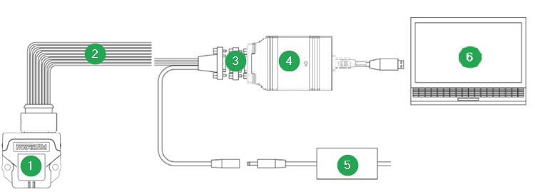
| # | Item |
|---|---|
1 |
CANlink wireless 4000 |
2 |
CLW4K Starter Cable |
3 |
CAN bus terminator D-Sub/D-Sub, 120Ω |
4 |
PCAN-USB - CAN/USB Interface |
5 |
Power supply unit |
6 |
PC with Proemion Firmware Programmer |
-
Ensure you have installed the Proemion Firmware Programmer with a version of at least
3.1.0.xby clicking on "About".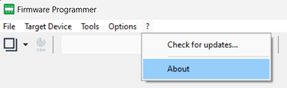 Figure 3. "About"
You can update an older version via "Check for updates…"
-
Download file
CANlink_wireless_400x_Second_Btldr.FwBinand open the file in the Firmware Programmer.
For the file, Go to Download Center > 01_Proemion_Devices > 08_CANlink wireless 4000 > 03_Firmware.
Ensure that theCommunication pathis set toConnection via CANand that the Node ID is set. Install the file to your device by pressing the "Start firmware download" button.
communication_path_and_node.png -
Download file
CANlink_wireless_400x.signed.binand open the file in the Firmware Programmer.
For the file, Go to Download Center > 01_Proemion_Devices > 08_CANlink wireless 4000 > 03_Firmware.
Ensure that theCommunication pathis set toConnection via CANand that theNode IDis set. Install the file to your device by pressing the "Start firmware download" button. -
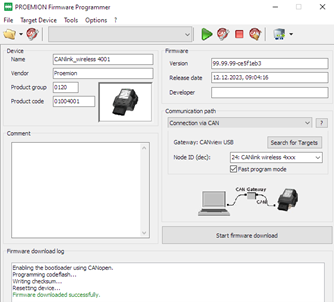
Download file
CANlink_wireless_400x_bundle.signed.binavailable in the "Bundle" subdirectory from the Download Center and open the file in the Firmware Programmer.
You will be prompted to confirm the configuration settings.
Ensure that theCommunication pathis set toSDO transfer to objectand that theNode IDis set.
You can then install the file to your device by pressing the "Start bundle download" button.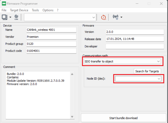 Figure 4. "Start bundle download"
This may take a few minutes: Approximately seven minutes to download the file to the CANlink wireless 4000, and approximately another six minutes for the firmware installation.
Do not reset the device during this process.Note that in case you use Firmware Programmer version 3.1.0.x you may still see an error message "Bundle Installation unsuccessful. Please try again or contact support" in the Firmware download log section.
This is likely a false alarm and can be ignored.
You can ensure that the firmware update was successful with the steps described in the next point. -
The firmware update is now complete.
To validate that the device firmware is indeed version 2.0 it is sufficient to check the following CANopen objects (using a generic CANopen tool):-
Check object
0x100A:0x00=2.0.0
This is the firmware version, and should be v2.x (the one you updated to) -
Check object
0x3007:0x03=1610.2.7.0.0.39
This is the Radio Module firmware, and should be v2.7 or greater.
(1610.x.y.z.z.z where x.y is 2.7 or greater).
-
7.3. Generic CANopen Tool
This section describes how to update the firmware of a CANlink wireless 4000 device from 1.x to 2.0.0 using a generic CANopen tool.
It requires that at least firmware version 1.2.0 and that the second stage bootloader is already installed on the device. This can be checked by confirming that object 0x500A:0x03 has the value Bl 2.1.
-
Download file
CANlink_wireless_400x.signed.binand write the file to object0x5FF0:0x00as a domain object via CANopen SDO on CAN1 or CAN2.
For the file, Go to Download Center > 01_Proemion_Devices > 08_CANlink wireless 4000 > 03_Firmware. -
Wait for the device to be ready.
-
Check object
0x100A:0x00is set to2.0.0. -
Write the
CANlink_wireless_400x_bundle.signed.binfile to object0x5FF1:0x01as a domain object via CANopen SDO on CAN1 or CAN2. -
Wait for the device to be ready, it will take some time.
-
The firmware update is now complete.
To validate that the device firmware is indeed version 2.0.0 check object0x3007:0x03, it should have the value1610.2.7.0.0.39.
8. Pin 7 digital output
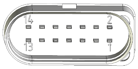
It is possible to use the pin 7 digital output of the Main Plug Connector interface of the CANlink wireless 4000.
There are two ways that this output can be used:
-
Manual
-
Wireless Connection Active
8.1. Manual Output
In this mode, the output can be switched manually by setting the value of an object in the Object Dictionary.
Set 0x3333:0x0F to 0x00 to output a low voltage, and 0x01 to output high.
This value is volatile, so it must be configured by an external controller after each reboot.
8.2. Wireless Connection Active
This mode represents the state of a wireless connection by setting the pin 7 output appropriately: High when connected, and Low when not connected.
This value can represent one of each of the three wireless interfaces: WiFi, Bluetooth and BLE:
-
For WiFi, set
0x3333:0x6F [Digital Output Connection Visualization Wifi]to0x01. -
For Bluetooth, set
0x3333:0x6E [Digital Output Connection Visualization Bluetooth SPP]to0x01. -
For BLE, set
0x3333:0x70 [Digital Output Connection Visualization BLE]to0x01.
In all cases, set the unwanted interface objects to 0x00 (disabled).
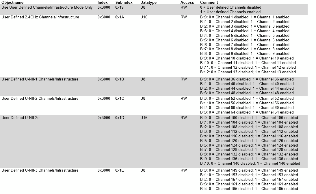
9. User-defined Wi-Fi channels
The user-defined Wi-Fi Channels feature gives the user the option to configure the Wi-Fi Client to scan only defined Wi-Fi channels.
The feature can be activated by writing value 1 into object 0x3000:0x19 [User Defined WiFi Channels] (the feature is deactivated by default).
By default, all channels are enabled, and must be cleared (set to zero) to be disabled in the following objects (according to the selected band).
2.4GHz Object
-
0x3000:0x1A [User Defined WiFi 2.4GHz Channels]
5GHz Objects
-
0x3000:0x1B [User Defined WiFi U-NII-1 Channels] -
0x3000:0x1C [User Defined WiFi U-NII-2 Channels] -
0x3000:0x1D [User Defined WiFi U-NII-2e Channels] -
0x3000:0x1E [User Defined WiFi U-NII-3 Channels]
9.1. Configuration of Wi-Fi Channels
In the following you find all channels listed for both the 2.4GHz Object and 5GHz Objects.
The configuration of the Wi-Fi channels is bit-coded.
You can individually define the channels to be scanned and connected to by setting the value 0 for disabling or value 1 for enabling again within the appropriate objects.
| Reducing the number of scan channels allows to have a faster Wi-Fi connection, as only the specified channels are scanned before connecting instead of the entire bandwidth of the Wi-Fi channels. |
9.1.1. Object 0x3000:0x1A [User Defined Wi-Fi 2.4GHz Channels]
-
Bit 0: Channel 1
-
Bit 1: Channel 2
-
Bit 2: Channel 3
-
Bit 3: Channel 4
-
Bit 4: Channel 5
-
Bit 5: Channel 6
-
Bit 6: Channel 7
-
Bit 7: Channel 8
-
Bit 8: Channel 9
-
Bit 9: Channel 10
-
Bit 10: Channel 11
-
Bit 11: Channel 12
-
Bit 12: Channel 13
9.1.2. Object 0x3000:0x1B [User Defined Wi-Fi U-NII-1 Channels (5GHz)]
-
Bit 0: Channel 36
-
Bit 1: Channel 40
-
Bit 2: Channel 44
-
Bit 3: Channel 48
9.1.3. Object 0x3000:0x1C [User Defined Wi-Fi U-NII-2 Channels (5GHz)]
-
Bit 0: Channel 52
-
Bit 1: Channel 56
-
Bit 2: Channel 60
-
Bit 3: Channel 64
9.2. Examples
In both of these examples, we enable the feature by setting 0x3000:0x19 [User Defined WiFi Channels] to 1.
-
Setting
0x3000:0x1A [User Defined Wi-Fi 2.4GHz Channels]to0x0104would enable 2.4GHz Wi-Fi connections on only channels 3 and 9. -
Setting
0x3000:0x1C [User Defined Wi-Fi U-NII-2 Channels (5GHz)]to0x0100and0x3000:0x1E [User Defined Wi-Fi U-NII-3 Channels (5 GHz)]to0x02would enable 5GHz Wi-Fi connections on only channels 132 and 153.
10. General Tips
10.1. WiFi
-
When selecting a Wi-Fi channel or band, we recommend choosing a channel number from 1 through 11. These channels are in the 2.4GHz band.
BAND CHANNELS 2.4GHZ
1
2
3
4
5
6
7
8
9
10
11
With a 2.4GHz channel, you can expect a greater range between devices.
Slightly higher bandwidth may be possible on the 5GHz band, at the cost of range.BAND CHANNELS 5GHz
36
40
44
48
If 2.4GHz channel is not possible, disable that band and select a 5GHz channel.
-
When configuring a CANlink wireless 4000, only one RF band should be enabled at one time.
This means either enable a 2.4GHz channel, or a 5GHz channel.
Proemion recommends choosing a 2.4GHz channel unless necessary.
10.2. CAN2
To enable CAN2 on the CANlink wireless 4000, ensure that 0x4000:0x16 [CAN Message Output CAN2] is set to 0x01 [Start Msg. Output active].
There can be an issue upgrading the device from v1.2 to v2.0 and this value is not enabled.
10.3. Factory Reset
When the device cannot be communicated with wirelessly, or over CAN — or there is some other issue, it can be useful to be able to reset the device to a known state, in order to start from that state.
This is known as a ‘Factory Reset’ (resetting the device to the state as it was when it left the factory).
If you have a standard CANlink wireless 4000, then the device will restart automatically configured:
-
as a Bluetooth Server. To connect with the Configurator.
-
with a CAN bit rate of 250 kbit/s
There are two ways of generating a Factory Reset.
10.3.1. Factory Reset over CANopen
When connected to the device (either wirelessly or by CAN bus), you can write 0x64616F6C to the CANopen object 0x1011:0x01 [Restore all default parameters].
This will reset all parameters, and reset after a few seconds.
For more information, see Factory Reset via CANopen SDO Request.
10.3.2. Factory Reset with the Starter Cable
If you have a Proemion Starter Cable (part number 136000197), you can reset the device back to the Factory configuration physically.
-
Slide the switch on the D-Sub connector (CAN1) towards the D-Sub connection.
 Figure 7. RM CAN Device Monitor Pro CANopen
 -
The LED on the D-Sub connector (CAN1) lights up red.
-
Wait until both LEDs on the device light up orange.
-
Slide the switch on the D-Sub connector (CAN1) toward the LED.
 Figure 8. RM CAN Device Monitor Pro CANopen
 -
Both LEDs light up green for a second and then change
-
ON LED: steady green
-
STATUS LED: green blinking
-
The device is now configured as a Bluetooth Server, and is in ready for pairing mode.
10.4. Antenna Positioning
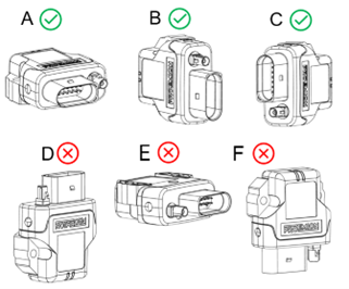
To prevent water ingress, we recommend installing the device in either orientation A, B or C.
For more information, see Mounting Orientation in the device manual.
To maximise range and performance, the side with the affixed label should point towards the face on the other device with the label.
So in most cases, orientation B or C is preferable (assuming a horizontal line-of-sight).
11. Appendix
A collection of interesting tools and links for use with the CANlink wireless 4000.
11.1. Useful Tools and Links
| Tool | Notes |
|---|---|
ByteCommand Protocol API |
The description of how to build devices to communicate with the CANlink wireless 4000 over our proprietary transmission protocol. |
RM CAN Device Monitor Pro CANopen |
Communicate with the CANlink wireless 4000 using CANopen. |
RM Device Programmer |
Program and update firmware. |
Proemion Configurator |
Reads and writes to device Object Dictionary |
Proemion SoftGateway |
{softgateway} |
Remote Service Tool |
Remote Service Tool Product Video |
Proemion Firmware Programmer |
Go to Download Center > 03_Proemion Tools Software > 01_Software > Firmware Programmer |
Technical datasheet |
11.2. Definitions and Acronyms
| Term | Definition |
|---|---|
Bridge Connection |
A connection between two CANlink wireless 4000 devices |
Downsampling |
Used when configuring filters (section 9 Filtering Messages), to prevent a message from being transmitted more frequently than the downsampling period. |
Gateway Connection |
A connection between a CANlink wireless 4000 device connected to a CAN bus, and other piece of equipment connected wirelessly to that CANlink wireless 4000. |
MultiPoint configuration |
When a CANlink wireless 4000 Server is in a MultiPoint network, more than one Client CANlink wireless 4000 can connect to that device. |
MultiTalk configuration |
An extension of MultiPoint mode, this is where the Server also additionally shares all received Client messages to all other Clients. |
Version: 11.0.988