Communication Units
The Communication Unit (CU) is the telematics device installed on a machine.
Note
A CU cannot connect to the DataPlatform if it is not assigned to a machine.
Communication Unit Details
To open the Communication Units tab, go to Settings > Administration > Organization and select Communication Units from the Top Menu Bar.
Alternatively, open the Communication Units page via the  icon on the Machine Page.
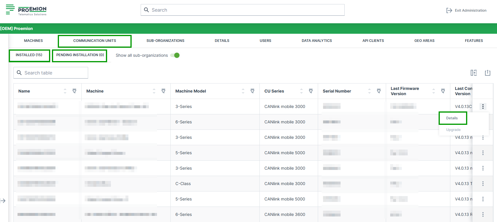
On the Communication Units page, users can find detailed information about all CUs assigned to their organization and manage them. For example, users can:
- See an overview of all devices including basic information such as device name, serial number, last login and logout on the physical device etc.
- Access detailed information for each CU via the Details option, see table below.
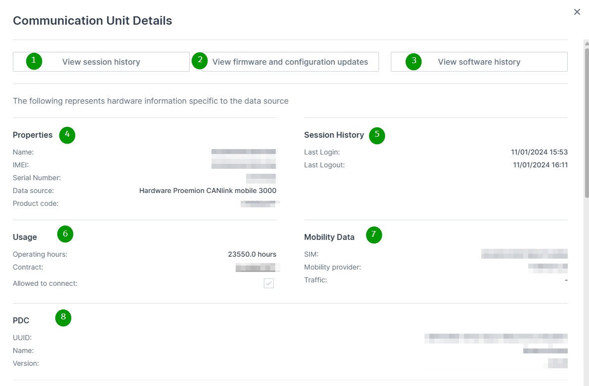
To view detailed information of a CU, open the three dots menu at the end of the row and choose Details.
| # | Item | Description |
|---|---|---|
| 1 | View session history | Button to open detailed session information. See Session History. |
| 2 | View firmware and configuration updates | Button linking to Firmware and Configuration Updates. |
| 3 | View software history | Button linking to Software Version History. |
| 4 | Properties | Display of CU master data: Name, IMEI, Serial Number, Hardware / Data Source, Product Code. |
| 5 | Session History (Summary) | Display of last Login and last Logout timestamps. |
| 6 | Usage | CU operating hours, contract information, and connection permission status. |
| 7 | Mobility Data | Information about the eSIM (ICCID), mobile network provider, and traffic. |
| 8 | PDC | Information about the assigned PDC file (UUID, Name, Version). |
Installed and Pending Communication Units
The Communication Units tab contains the following two sub-tabs, to clearly separate active devices from devices that still require activation:
-
Installed: Displays all Communication Units that have already been activated and are live. These CUs are fully provisioned, assigned to a machine, and actively transmitting data. This tab is selected by default.
-
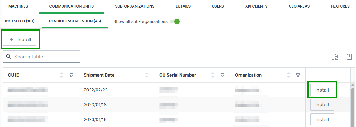
Pending Installation: Displays Communication Units that have already been shipped to the customer but are not yet activated. These devices are visible to support a transparent activation process and are ordered by shipment date (oldest first) to help users prioritize the activation of older devices.
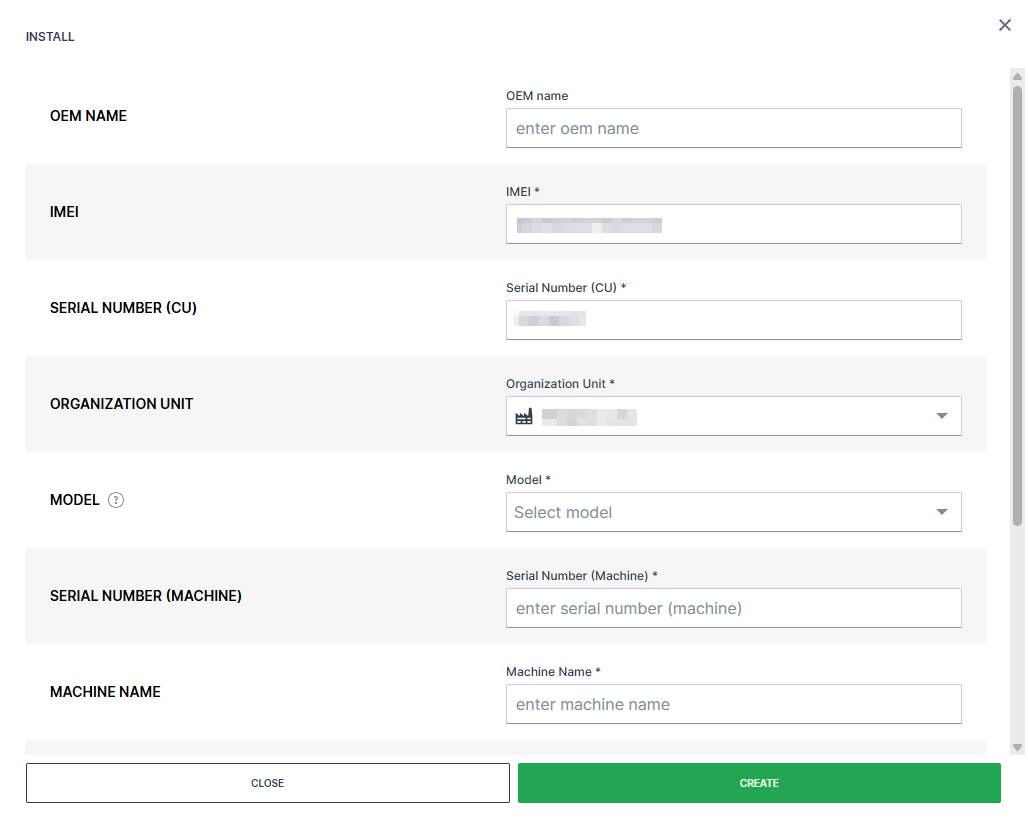
For Communication Units listed under Pending Installation, an Install button is available once at the top of the table and at the end of the row of a machine to start the activation process. When selected, the Install dialog with the activation workflow opens with the CU pre-selected and key device information such as the serial number and IMEI number automatically filled in.
This allows users to quickly assign the device to a machine and complete the activation with minimal manual input. Once a Communication Unit has been assigned to a machine and successfully activated, it automatically moves from the Pending Installation sub-tab to the Installed sub-tab.
Communication Units listed under Pending Installation may belong to organizations that were automatically created by Proemion based on shipment information.
For further information refer to system organizations.
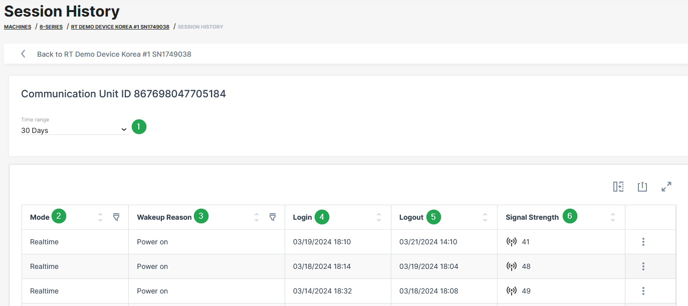
Session History
The Session History allows to gain additional information about the operating mode, wakeup reason, duration and signal strength of each session within a given time range.
| # | Item | Description |
|---|---|---|
| 1 | Time range | Drop down menu to define the time range for the session history |
| 2 | Mode | Display of the operating mode (Online, Logging, Realtime or Unknown). "Online" is available for the CANlink® mobile 3600 and {{ wl_product_name_clm1000 }} devices. For more information, read CANlink mobile 3600 Online feature. |
| 3 | Wake-up reason | Details about the wake-up reason of the device for example due to ignition, power on, CAN activity, real-time clock–based wake-ups (interval or alarm) and accelerometer events. Not all wake-up reasons are applicable to all device types. |
| 4 | Login | Date and time of session start. |
| 5 | Logout | Date and time of session stop. |
| 6 | Signal strength | Mobile network signal quality at session start. Values are shown in decibel unit ( dB). For more information, see Signal Strength. |
| 7 | Export | Table Options. |
Signal Strength
For an evaluation of the mobile signal quality, the values need to be converted to RSSI values with the formula:
RSSI = 2*x - 113 dBm (Formula for CANlink mobile 3600)
where x is the value from the CANlink mobile (Index 0x5251 Sub 0x00 in the CANlink mobile 36xx).
The following table shows the mapping of RSSI to db:
Note
31 in all cases means "maximum". The smaller the dBM the better the signal strength is.
| dB | RSSI (RSSI = 2*x - 113 dBm) |
|---|---|
| 0 | -113dBm or less |
| 1 | -111dBm |
| 2...30 | -109dBm... -53dBm |
| 31 | -51dBm or greater |
| 99 | Not known or not detectable |
| 100 | -116dBm or less |
| 101 | -115dBm |
| 102...190 | -114dBm...-26dBm |
| 191 | -25dBm or greater |
| 199 | Not known or not detectable |
| 100~199 | Extended to be used in TD-SCDMA indicating received signal code power (RSCP) |
The next table describes the meaning of the signal values (source of the table: RSSI Teltonika)
Note
The RSSI on its own is useful when comparing different antennas on your device, or for example to check whether directional antennas have a good orientation. But there might be a strong signal but with a lot of (other) traffic that will lead to poor reception. Thereby, it needs to be considered that there is no linear mapping like "RSSI value > x = good reception". But the following table gives a good indication.
| RSSI | Signal strength | Description |
|---|---|---|
| > -65 dBm | Excellent | Strong signal with maximum data speeds |
| -65 dBm to -75 dBm | Good | Strong signal with good data speeds |
| -75 dBm to -85 dBm | Fair | Fair but useful, fast and reliable data speeds may be attained, but marginal data with drop-outs is possible |
| -85 dBm to -95 dBm | Poor | Performance will drop drastically |
| < = -95 dBm | No signal | Disconnection |