CANlink mobile 10000 Device Manual
Preamble
Legal Notice
All brands and trademarks named in this document and possibly protected by third-party rights are subject without limitation to the terms of the valid trademark law and intellectual property rights of their respective registered owner.
You can find a list of the free-source and open-source software as well as copyright notes, license texts and, if applicable, the relevant source code on our website under the link: Free & Open Source Software.
Observe all local and regional laws and provisions as well as the safety instructions contained in this document.
Contact
Proemion GmbH
Donaustr. 14
36043 Fulda, Germany
Phone: +49 661 9490-0
Fax: +49 661 9490-111
info@proemion.com
Proemion Corp.
US Subsidiary
241 Taylor St., Suite 301
Dayton, Ohio 45402, USA
Phone: +1 937 558 2211
Fax: +1 937 641 8787
info-dayton@proemion.com
Proemion Ltd.
373 Gangnam-daero Seocho-gu
Seoul, 06621, South Korea
Phone: +82 2 6080 9490
Fax: +82 504 484 9490
info-seoul@proemion.com
Website: Proemion
About This Manual
This document is part of the product and provides important information on the intended use, safety, installation, and operation of the devices described below. The document is intended for qualified technicians and electricians with advanced knowledge in electrical engineering and field bus systems, allowing them to estimate the risks and hazards of operating the device and to integrate it into systems with components of other manufacturers.
Safety Levels
The safety levels have the following meanings:
Danger
Severe injury or death. Probability: very high
Warning
Severe injury or death. Probability: possible
Note
Indicates notes and information
Other information
Tip
Valuable information
Tasks
Tasks are structured as follows:
- Aim of the task
- Prerequisites for the described task.
- Step 1.
-
Step 2.
Result of correct performance of the task.
-
Step 3.
Lists
Lists are indicated as follows.
- List item
Notations
The following notations are used in this document:
| Designation | Representation |
|---|---|
| Keys, commands, messages | Keys, commands, messages |
| Navigation in menus, functions of the user interfaces, file paths | FILE > SAVE > Click OK button |
| Accessories | Cable, adapter |
About the Device
The following sections provide an overview of the device's operating elements and functions as well as the intended use of the device. Additionally, it provides an overview of the available types and certificates.
For more detailed information, see Annex.
Important Device Information
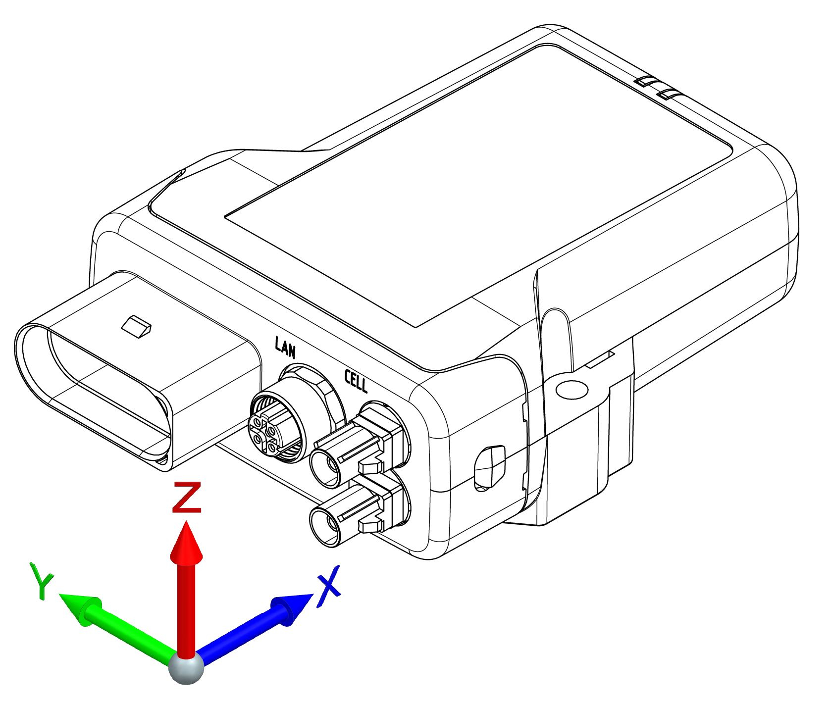
Device Elements
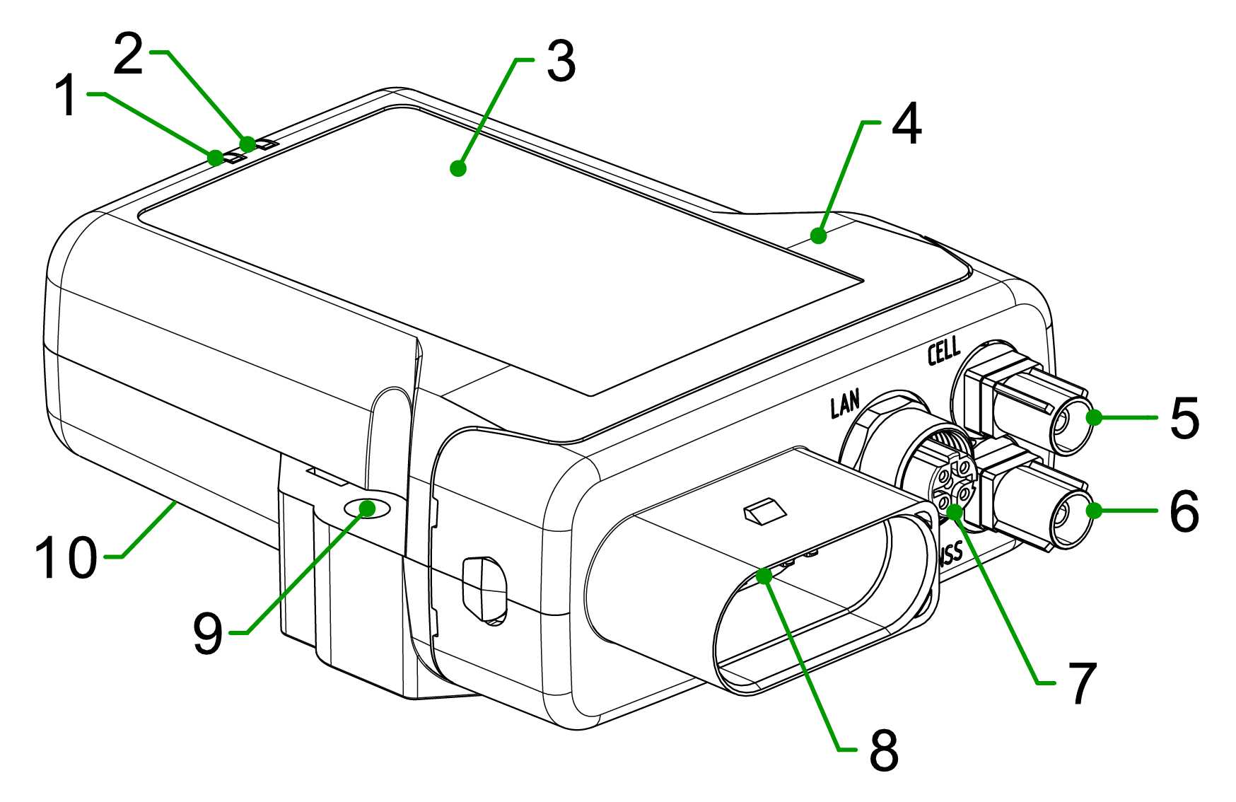
| # | Item |
|---|---|
| 1 | ON LED |
| 2 | STATUS LED |
| 3 | Type label front-side |
| 4 | Housing |
| 5 | Mobile radio antenna connector |
| 6 | GNSS antenna connector |
| 7 | Ethernet connector |
| 8 | Main plug connector |
| 9 | Fixing holes |
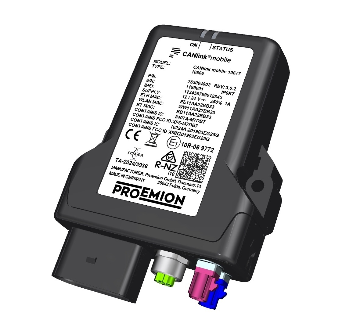
Type Label
The device type label is located on the front of the housing and provides the following information:
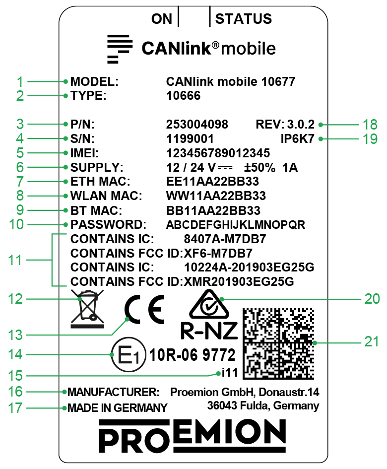
| # | Item |
|---|---|
| 1 | Model designation |
| 2 | Type |
| 3 | Part number |
| 4 | Serial Number |
| 5 | IMEI number |
| 6 | Power supply |
| 7 | Ethernet MAC address |
| 8 | WLAN MAC address |
| 9 | Bluetooth MAC address |
| 10 | Password, initial |
| 11 | IC-ID, FCC-ID |
| 12 | Disposal symbol |
| 13 | CE mark |
| 14 | ECE certification mark |
| 15 | Product Change Index |
| 16 | Manufacturer address |
| 17 | Country of origin |
| 18 | Hardware version |
| 19 | Protection class |
| 20 | RCM (Regulatory Compliance Mark, Australia/New Zealand) |
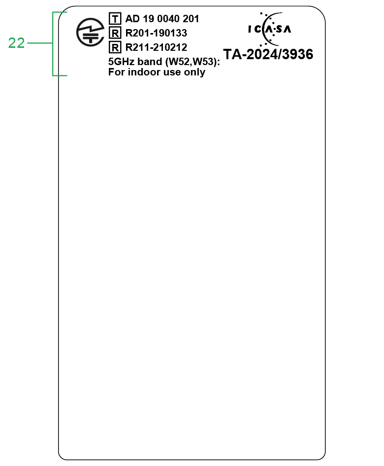
| 21 | Traceability code |
| 22 | ICASA & TRC Certification (South Africa, Taiwan) |
Note
Use of solvents on the product label can remove or destroy product information.
- Keep solvent-containing substances away from the label!
Traceability code
The traceability code contains the following information. Example:
253004093000000000001122333(I)867698041234567(W)W12233445566(B)B12233445566(E)E12233445566
| Item | Description |
|---|---|
| 9-digit part number: | 253004093 |
| Serial number 0-padded: | 1122333 |
(I) followed by the IMEI Number: |
867698041234567 |
(W) followed by the WLAN MAC Address: |
12233445566 - only certain types |
(B) followed by the Bluetooth MAC Address: |
12233445566 - only certain types |
(E) followed by the Ethernet MAC Address: |
12233445566 |
Note
The device's type label contains important information. Do not remove the type label!
Intended Use
The device is used for the wireless transmission of CAN and Ethernet data from a vehicle or stationary system according to the 2G, 3G and 4G cellular standards.
Depending on the type, you can also receive and transmit GNSS positioning data via Ethernet/Wi-Fi interfaces.
Depending on the type, you can also use the Ethernet interface to access the graphical Configuration Web User Interface, or to go online via Ethernet, and/or to grant access to the Internet for other connected network participants. The Launch Kit provides the Ethernet cable to connect to a PC.
Depending on the type, the device is equipped with an integrated battery. The integrated battery provides temporary backup in the event of power failure. It is not intended as a permanent power source for the device.
The device is suitable for use in mobile and stationary systems for industry, small businesses, earth-moving and construction machinery and in agricultural and forestry machinery.
The device can be used in environments that require protection class IP6K7.
Note
Protection class IP6K7 is only ensured when all the device connectors are provided with plug connectors or corresponding protection caps/protection plugs.
Please refer to chapter Connectors, Cables and Cleaning.
Only use the device within the permitted temperature range and the other parameters specified in the technical data. Any use other than that described under “Intended use” is considered unintended use.
MISUSE
The device does not comply with Directive 2014/34/EU and may not be used in potentially explosive areas. The device must not be cleaned with a pressure washer.
Note
Risk of Property damage.
- The device must not be permanently submerged in water and must be protected from direct high-pressure jets.
- The device must not be exposed to following non-recommended substances: oxidizing agent solutions, mineral acids, formic acid, strong alkalis, phenols, cresols and glycols. Read also the Technical Data.
- During transport or when you unscrew the M12 connector, there is a possibility that the seal (O-ring) will become loose/lost. You must ensure that the O-ring is present on the M12 connector before mounting the mating connector. If no plug is connected, a dummy plug (not a cover cap) must be used so that the O-ring is clamped between the sleeve and plug. This prevents water from penetrating and also prevents vibrations. Dummy plug example: {dummy-plug}.
QUALIFIED PERSONNEL
The device must only be put into operation by qualified technicians and electricians with advanced knowledge of electrical engineering and fieldbus systems. The specialist personnel must know the contents of this manual and always have access to it.
Risk of property damage
Do not open the device housing unless you are explicitly instructed to do so. Use only approved tools and follow the specified procedures. Unauthorized opening may damage the device and may affect warranty coverage. The device must be inspected and repaired only by trained Proemion service technicians. Contact our Service and Support.
Note
Risk of Property damage.
Device is not installed in accordance with the setup requirements and permitted environmental conditions.
- The system integrator is responsible to install the device according to the specification and take corrective action in regards mechanical protection against soiling, water penetration and vibration.
- If necessary, install external protection shields. For example, an additional housing to protect the device from jet water.
- Install the device according to the recommended mounting position.
- Ensure that the cable management fulfills the required mechanical protection, insulation from vibration and strain.
Conformity
For details of the corresponding approval tests, see Certification and Qualification. The device meets the requirements of the following standards and legal requirements:
 |
Simplified CE Declaration of Conformity |
 |
ISED Compliant This device complies with the directives, standards and normative documents. |
 |
FCC Compliant This device complies with Part 15 of the FCC rules. Operation is subject to the following conditions: * The device may not cause harmful interference. * The device must accept any interference received, including interference that may cause undesired operation. |
 |
E1 Compliant This device has been approved by the KBA (Kraftfahrtbundesamt, Federal Office for Motor Traffic) as compliant with Regulation No. 10. |
 |
TELEC compliant for Japan This device is certified under business law  AD190040201 and radio law AD190040201 and radio law  R201-190133. The Model CANlink mobile 10677 is additionally certified under radio law R211-210212 and utilizes the 5GHz band (W52, W53): For indoor use only. R201-190133. The Model CANlink mobile 10677 is additionally certified under radio law R211-210212 and utilizes the 5GHz band (W52, W53): For indoor use only. |
The full text of the declarations of conformity, as well as further certificates (e.g. FCC and Bluetooth SIG), are available at our website Declarations of Conformity (DoC)for CANlink® mobile 1000 series.
Go to 01_Proemion_Devices > 01_CANlink mobile 1000 > CANlink mobile 10000 Radio Type Approvals Country List.pdf in the Download Center for a full list of countries where CANlink® mobile 10000 devices have a radio approval.
Available Models/Types
The CANlink® mobile 10000 series includes several Models and Types that differ by their provided interfaces and hardware options. The following optional upgrades are available to tailor the device to specific customer needs:
-
Wireless module for Wi-Fi® and Bluetooth
-
Integrated battery
-
Dualband GNSS
For detailed information on the supported mobile radio and Wi-Fi® standards as well as the Bluetooth profiles, see Chapter Interfaces. The table below summarizes the available Models, Variants, and their key features.
The CRT Types are shipped with two CODESYS licenses activated by default:
- CODESYS Control Basic M
- CODESYS IIoT Libraries SL
The Model designation remains CANlink mobile 10677 for all Types and Variants.
Available Types for Model 10677
| Type | Variant Description | Part number | WLAN/ Bluetooth | GNSS Receiver | Battery | # CAN IF | CAN3 | Co-MCU |
|---|---|---|---|---|---|---|---|---|
| 10666 | Standard3 | 253004098 | Yes | Singleband | Yes | 3 | Yes | No |
| 10666 | CRT | 253004818 | Yes | Singleband | Yes | 3 | Yes | No |
| 10662 | Standard3 | 253004802 | Yes | Singleband | No | 3 | Yes | No |
| 10662 | CRT | 253004819 | Yes | Singleband | No | 3 | Yes | No |
| 106771 | CRT | – | Yes | Dualband | Yes | 3 | Yes | Yes2 |
| 106721 | CRT | – | Yes | Dualband | No | 3 | Yes | No |
| 106671 | CRT | – | Yes | Singleband | Yes | 3 | Yes | Yes2 |
All Models/Types are equipped with an eSIM card using the 4G Mobile Radio Interface and include an integrated Acceleration Sensor and Gyro Sensor.
Scope of Delivery
-
CANlink mobile 10xxx
-
Product information sheet with brief CE declaration
Launch Kit
The Launch Kit (253000183) contains all hardware components required for putting the CANlink mobile into operation. Before you can use the DataPlatform, you must obtain the corresponding access. This access must be a component of the quotation and finally of the sales order.
| Material | QTY |
|---|---|
| Ethernet-Cable, M12 4-pol. (D) CAT6 - RJ45, 2m | 1 |
| CLM3600/10K Startercable 6open 3dsub 1pw 2m | 1 |
| Cable MTII 14pin code1 14open 2m | 1 |
| Antenna LTE GNSS DA 3M0 FAKRA-D FAKRA-C FA | 1 |
| PCAN-USB - CAN/USB Interface | 1 |
| CAN bus terminator D-Sub/D-Sub, 120Ω | 1 |
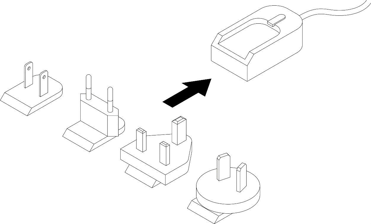
| Power supply unit with set of connectors (US, EU, UK, AU) | 1 |
| Mounting kit M5 Enclosure GH1208 | 1 |
| CANlink Connector Kit | 1 |
| CANlink® mobile Opening Tool for GH1209 housings (see CANlink mobile Opening Tool manual) | 1 |
Software and Accessories
Additional software can be downloaded from our Download Center under: 03_Proemion Tools Software > 01_Software.
| Material | Part Number |
|---|---|
| PCAN-USB - CAN/USB Interface CAN-PC communication gateway for configuration and test purpose | 257001041 |
| CANlink Connector Kit MT II 14-pin socket housing, 14x MT II contact type A, 14x MT II gray single-wire sealing, 14x dummy plugs only for machine processing, refer to Connector Kit Datasheet for further information | 132600031 |
| ERGOCRIMP HAND TOOL 539635-1 without die set Hand Tool Direct order at supplier | |
| ERGOCRIMP DIE SET for MICRO Timer and Micro Timer (SWS) 539663-2 Micro Timer Direct order at supplier | |
| MT2 A REC 1.6 Contact SWS Sn (LP) for crimping with hand tool Crimping Hand Tool Direct order at supplier | |
| CAN bus termination, D-Sub/D-Sub CAN 120 Ohm | 157000033 |
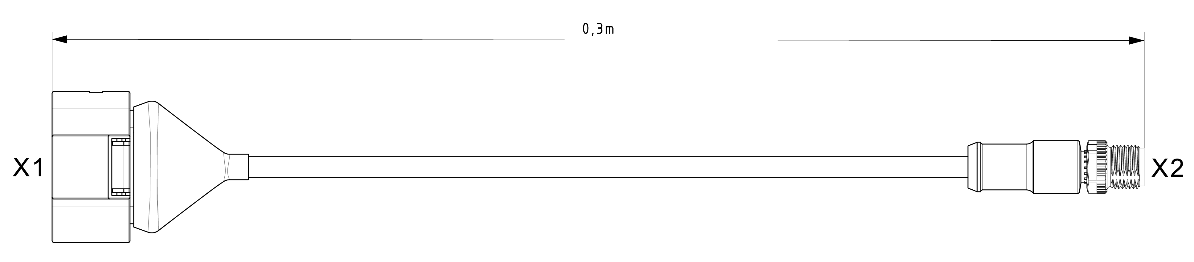
| MT II socket, 14-pin, cod.1, open, 30 cm Connection cable for main plug connector, 14-pin with open cable, 0.3m | 136000188 |
| MT II socket, 14-pin, cod.1, open, 2 m Connection cable for main plug connector, 14-pin with open cable ends, 2 m | 136000198 |
| CLM3600/10K Startercable 6open 3dsub 1pw 2m (Starter cable for main plug connector) Cable for initial startup with complete connector assignment for main plug connector, 14-pin, ready-to-use, 2 m long | 136000202 |
| Cable, M12 4-pin (D) CAT6 - RJ45, 2m Ethernet cable | 136000207 |
| ANT LTE GNSS DA 3M0 FAKRA-D FAKRA-C FA (Shark fin) GNSS / mobile radio antenna | 157000109 |
| ANT LTE GNSS DA 3M0 FAKRA-D FAKRA-C FAR (Flat Rectangle) GNSS / mobile radio antenna | 157000121 |
| ANT GNSS DB DA 3M0 FAKRA-C FA1 GNSS Dualband antenna 1available on request |
157000131 |
| Mounting kit M5 Enclosure GH1208 fixing set | 141000017 |
| Power supply unit, US EU UK AU 24V/0.83A/20W Power supply unit without AC plug 24 V 0,83 A 20 W, plug adapter set (US, EU, UK, AU), adapter DC 5.5x2 mm BU / 3.5x1.35 mm ST | 257004007 |
| CODESYS Control Basic M (License Key)1 | 157 002 066 |
| CANlink® mobile Opening Tool for GH1209 housings (see CANlink mobile Opening Tool manual) | 157012001 |
-
Read in CODESYS Control Basic M bundle what is included in the CODESYS license. Note that this license will only include up to 2 CANopen/Profibus/Modbus/J1939 instances.
Each interface, like for instance each CAN channel, needs a dedicated instance.
If you need more instances, you would need to upgrade your license. For example, J1939 messages in the 3 CAN channels. ↩
Safety Information
Safety Instructions
This section contains safety instructions that must be followed to prevent injury, death, or damage to the device.
Intended Use
The device is designed for use in industrial environments as well as in earth-moving machinery.
The device is not intended for safety-related applications.
Foreseeable Misuse
The device must not be used in the following ways:
- Use in safety-related or safety-critical applications (e.g. according to ISO 26262)
- Use in potentially explosive atmospheres
- Use as a permanent power source via the internal battery
- Cleaning with high-pressure equipment (e.g. pressure washer)
- Any use outside the specified environmental and operating conditions
Qualified Personnel
The device must only be installed, commissioned, and serviced by qualified personnel.
Qualified personnel are trained technicians or electricians with knowledge of:
- Electrical systems
- Fieldbus communication (e.g. CAN)
- Applicable safety regulations
Personnel must have read and understood this documentation and have access to it at all times.
The responsible organization must ensure that only qualified personnel work with the device.
Functional Safety Restrictions
DANGER: Use in safety-related applications
Risk of severe or fatal injury.
The device operates using wireless communication. Data transmission cannot be guaranteed at all times due to possible network limitations, interference, or device malfunctions. The device is not designed, certified, or authorized for use in functional safety or safety-related applications (e.g. according to ISO 26262). Any failure, misconfiguration, or misuse may lead to malfunction of safety-critical systems.
- Never use this device in applications where human safety depends on its correct operation.
- Never use the device to influence or interfere with safety-relevant communication (e.g. powertrain CAN or other safety-related networks).
- The system integrator is responsible for ensuring that the device does not affect safety functions.
- Do not rely on wireless communication for critical or safety-relevant data transmission.
Explosion and Hazardous Environments
DANGER: Explosion hazard
Risk of severe or fatal injury.
Operation of electrical equipment in potentially explosive atmospheres may cause ignition.
- Observe all applicable regulations for hazardous areas.
- Do not install antennas near flammable substances (e.g. fuel tanks).
Aircraft Restrictions
DANGER: Interference with aircraft systems
Risk of severe or fatal injury.
Radio frequency emissions may interfere with aircraft communication systems.
- Disconnect the power supply before entering an aircraft.
- Ensure the device cannot be switched on during flight.
Electrical Safety
WARNING: Electric shock
Risk of severe or fatal injury.
- Do not use the device if there is visible damage.
- Do not open or repair the device.
- Repairs must only be carried out by the manufacturer.
Radio Frequency (RF) Exposure
WARNING: RF exposure and interference
Risk of severe or fatal injury.
Radio frequency emissions may interfere with medical and electronic equipment.
- Keep a minimum distance of 20 cm between antennas and persons.
- Do not operate the device near medical equipment (e.g. pacemakers) without verifying compatibility.
- Follow local regulations in hospitals and sensitive environments.
Installation and Power Supply Risks
WARNING: Improper installation or power supply
Risk of injury or device damage.
- Installation must be performed by qualified personnel.
- Protect the power supply circuit with an external 2 A fuse.
- Disconnect all connections before working on the device.
Mechanical Protection
Risk of property damage
The device is protected against mechanical impacts according to class IK07 (IEC 62262, impact energy 2 joules).
- If higher protection is required, additional external protection must be provided.
- If necessary, install external protection measures such as protective housings or shields to protect the device from external influences (e.g. water spray or mechanical impact).
Device Integrity and Handling
Risk of property damage
Improper handling may lead to device malfunction or damage.
- Do not use damaged cables or connectors.
- Ensure all connections are correctly assigned and not forced.
- Do not expose the device to solvents.
- Do not immerse the device in liquids.
- Ensure all connectors are properly sealed to maintain protection class (IP).
Cleaning and Environmental Limits
Risk of property damage due to water exposure
The device is resistant to water jets according to IPxK5. Higher pressure or flow rates may cause damage.
- Do not clean the device with a pressure washer.
Antenna Placement
Interference due to incorrect antenna positioning
Improper antenna placement may reduce performance or cause interference.
- Maintain a minimum distance of at least 1/4 wavelength between antennas.
- Avoid distances that are multiples of the wavelength.
- Do not operate antennas together with other transmitters unless properly evaluated.
CE Notes European Union
The devices described in this device manual may only be used in mobile or stationary systems in which the distance between antennas and persons is at least 20 cm. Furthermore, antennas may only be operated in conjunction with other antennas or transmitters when the correct horizontal distance between them is observed.
Note
Loss of CE conformity is possible. Only use antennas with a maximum antenna gain (incl. cable and connector loss) of:
CANlink® mobile 10000:
- 2.98dBi (GSM)
- 2dBi (DCS)
- 1.53dBi (WCDMA B1)
- 2.98dBi (WCDMA B8)
- 2.29dBi (WCDMA B5)
- 1.53dBi (LTE B1)
- 2dBi (LTE B3)
- 2.29dBi (LTE B5)
- 3dBi (LTE B7)
- 2.98dBi (LTE B8)
- 2.64dBi (LTE B20)
- 3.95dBi (LTE B28)
- 2.06dBi (LTE B38)
- 1.88dBi (LTE B40)
Note
Loss of CE conformity is possible. The allowed maximum equivalent isotropically radiated power (EIRP) according to ETSI for Bluetooth is:
Model CANlink mobile 10677 with Bluetooth
- Bluetooth Classic: max. 9.76dBm at 2.402 - 2.480 GHz
- Bluetooth LE: max. 9.98dBm at 2.402 - 2.480 GHz
Note
Loss of CE conformity is possible. The allowed maximum equivalent isotropically radiated power (EIRP) according to ETSI for Wi-Fi® is:
Model CANlink mobile 10677 with Wi-Fi®
- max. 18.58dBm at 2.412 - 2.472 GHz
- max. 19.62dBm at 5.150 - 5.350 GHz
- max. 17.64dBm at 5.470 - 5.725 GHz
- max. 13.88dBm at 5.725 - 5.825 GHz
Changes or modifications to this device not expressly approved by the manufacturer can void the user's authority to operate the device under CE rules.
Note
Loss of CE conformity is possible.
Applicable for Model CANlink mobile 10677 with Wi-Fi®
This device is restricted to indoor use only when operating Wi-Fi® channels in the frequency range 5150 to 5350 MHz for the following countries:

FCC Notes USA
The devices described in this device manual may only be used in mobile or stationary systems in which the distance between antennas and persons is at least 20 cm. The antennas must further not be co-located or operated in conjunction with any other antennas or transmitters.
Note
This device has been tested and found to comply with the limits for a Class B digital device pursuant to part 15 of the FCC rules. These limits are designed to provide adequate protection against harmful interference in a residential installation. This device generates, uses, and can radiate radio frequency energy and, if not installed and used in accordance with the instructions, may cause interference to radio communications. There is no guarantee that interference will not occur in a particular installation. If this device does cause interference to radio or television reception, which can be determined by switching the device on and off, the user is advised to try to correct the interference by one or more of the following measures:
- Realign the receiving antenna or put it in a different place.
- Increase the distance between the device and the receiver.
- Connect the device and the receiver to different supply circuits.
- Consult the dealer or an experienced radio/TV technician for help.
Note
Loss of FCC certification possible. Only use antennas with a maximum antenna gain (incl. cable and connector loss) of:
CANlink® mobile 10000:
- 8dBi in WCDMA Band 2/LTE Band 2/7/25/38/41
- 5dBi in WCDMA /LTE Band 4
- 8.6dBi in GSM850
- 10.19dBi in PCS1900
- 9.42dBi in WCDMA Band 5
- 9.41dBi in LTE Band 5
- 8.7dBi in LTE Band 12
- 9.16dBi in LTE Band 13
- 9.36dBi in LTE Band 26(814-824)
- 9.41dBi in LTE Band 26(824-849)
Changes or modifications to the device not expressly approved by the manufacturer can void the user's authority to operate the device under FCC rules.
ISED Notes Canada
English
This product meets the applicable Innovation, Science and Economic Development Canada technical specifications.
This Class B equipment complies with the applicable ISED RSSs Standards and CAN ICES-003. Operation is subject to the following two conditions:
(1) This device may not cause interference, and
(2) This device must accept any interference, including interference that may cause undesired operation of the device.
Radiation Exposure Statement
This device complies with radiation exposure limits prescribed for an uncontrolled environment for fixed and mobile use condition. This equipment should be installed and operated with minimum distance of 20cm between the radiator and the body of the user or nearby persons.
Maximum Cellular Antenna Gain
The maximum antenna gain including cable and connector loss in a fixed or mobile exposure condition must not exceed +5dBi for all applicable GSM (850, 1900), WCDMA (2, 4, 5) and LTE (2, 4, 5, 7, 12, 13, 25, 26, 38, 41) Bands.
Changes or modifications to this device not expressly approved by the manufacturer can void the user's authority to operate the device under ISED rules.
Warning
Harmful interference.
Applies to Model CANlink mobile 10677 with WLAN
This device is restricted to indoor operation only in the band 5150-5250 MHz to reduce the potential for harmful interference to co-channel mobile satellite systems.
However, original equipment manufacturer (OEM) devices, which are installed in vehicles by vehicles manufacturers, are permitted.
The high-power radars are allocated as primary users (i.e., priority users) of the bands 5250-5350 MHz and 5650-5850 MHz and that these radars could cause interference and/or damage to this device.
This device is not capable of transmitting in the band 5600-5650 MHz in Canada.
Français
Ce produit est conforme aux spécifications techniques applicables d'Innovation, Sciences et Développement Économique Canada.
Cet équipement de classe B est conforme aux normes ISDE RSS applicables et à la norme CAN ICES-003. Son fonctionnement est soumis aux deux conditions suivantes:
(1) Cet appareil ne doit pas provoquer d'interférences et
(2) Cet appareil doit accepter toute interférence, y compris les interférences qui peuvent provoquer un fonctionnement indésirable de l'appareil.
Déclaration d'exposition aux rayonnements
Cet appareil est conforme aux limites d'exposition aux rayonnements prescrites pour un environnement non contrôlé dans des conditions d'utilisation fixe et mobile. Cet équipement doit être installé et utilisé à une distance minimale de 20 cm entre le radiateur et le corps de l'utilisateur ou des personnes à proximité.
Gain d'antenne cellulaire maximal
Le gain d'antenne maximal, y compris les pertes du câble et du connecteur dans des conditions d'exposition fixe ou mobile, ne doit pas dépasser +5 dBi pour toutes les bandes GSM (850, 1900), WCDMA (2, 4, 5) et LTE (2, 4, 5, 7, 12, 13, 25, 26, 38, 41).
Les changements ou modifications de cet appareil non expressément approuvés par le fabricant peuvent annuler le droit de l'utilisateur à utiliser l'appareil selon la réglementation ISDE.
Avertissement
Interférences nuisibles
S'applique au Model CANlink mobile 10677 avec WLAN
Cet appareil est limité à un fonctionnement en intérieur uniquement dans la bande 5150-5250 MHz pour réduire le potentiel d'interférences nuisibles aux systèmes mobiles par satellite sur le même canal.
Toutefois, les dispositifs de fabricant d'équipement d'origine (OEM), qui sont installés dans les véhicules par leurs constructeurs, sont autorisés.
Les radars haute puissance sont considérés comme utilisateurs principaux (c'est-à-dire utilisateurs prioritaires) des bandes 5250-5350 MHz et 5650-5850 MHz et ces radars pourraient causer des interférences et/ou endommager cet appareil.
Cet appareil n'est pas capable d'émettre dans la bande 5600-5650 MHz au Canada.
Warranty and Liability
Proemion assumes no liability for defects caused by normal wear, external influences and incorrect installation, operation or maintenance. This also applies if the customer or a third party modifies the devices, any accessories, or the software without permission from Proemion.
Functionality and Features
Functions
The following sections contain information on device functionality and features. It provides details of the operating modes, connectors, cables, pin assignments, interfaces and indicator elements.
The CRT Types are shipped with two CODESYS licenses activated by default:
- CODESYS Control Basic M
- CODESYS IIoT Libraries SL
The Model designation remains CANlink mobile 10677 for all Types and Variants.
Available Types for Model 10677
| Type | Variant Description | Part number | WLAN/ Bluetooth | GNSS Receiver | Battery | # CAN IF | CAN3 | Co-MCU |
|---|---|---|---|---|---|---|---|---|
| 10666 | Standard3 | 253004098 | Yes | Singleband | Yes | 3 | Yes | No |
| 10666 | CRT | 253004818 | Yes | Singleband | Yes | 3 | Yes | No |
| 10662 | Standard3 | 253004802 | Yes | Singleband | No | 3 | Yes | No |
| 10662 | CRT | 253004819 | Yes | Singleband | No | 3 | Yes | No |
| 106771 | CRT | – | Yes | Dualband | Yes | 3 | Yes | Yes2 |
| 106721 | CRT | – | Yes | Dualband | No | 3 | Yes | No |
| 106671 | CRT | – | Yes | Singleband | Yes | 3 | Yes | Yes2 |
All Models/Types are equipped with an eSIM card using the 4G Mobile Radio Interface and include an integrated Acceleration Sensor and Gyro Sensor.
Wi-Fi®
Wi-Fi® Encryption
| Name | Authentication | Data Protection | Notes |
|---|---|---|---|
| WPA2 + WPA3 Personal | Yes | Yes | Hotspot/Access Point Mode: Key must be between 16 and 63 characters long. Client Mode: Key must be between 8 and 63 characters long. |
| WPA3 Personal only (SAE) | Yes | Yes | Hotspot/Access Point Mode: Key must be between 16 and 63 characters long. Client Mode: Key must be between 8 and 63 characters long. |
Note
Enterprise WiFi may be supported as part of a separate project agreement. For more information, contact Service and Support.
Wi-Fi® Frequencies and Channels
The device's Wi-Fi® interface features automatic domain recognition and supports the following regulatory domains: WORLD, ETSI, FCC. If neither ETSI nor FCC are recognized, the radio module uses WORLD as a standard.
| Name | Band | TX Channel |
|---|---|---|
| World | 2.4 Ghz | 1, 2, 3, 4, 5, 6, 7, 8, 9, 10, 11 |
| U-NII-1 | 36, 40, 44, 48 | |
| U-NII-2 | 52, 56, 60, 64 | |
| U-NII-2e | 100, 104, 108, 112, 116, 132, 136, 140 | |
| U-NII-3 | - | |
| ETSI | 2.4 GHz | 1, 2, 3, 4, 5, 6, 7, 8, 9, 10, 11, 12, 13 |
| U-NII-1 | 36, 40, 44, 48 | |
| U-NII-2 | 52, 56, 60, 64 | |
| U-NII-2e | 100, 104, 108, 112, 116, 120, 124, 128, 132, 136, 140 | |
| U-NII-3 | 149, 153, 157, 161, 165 | |
| FCC | 2.4 GHz | 1, 2, 3, 4, 5, 6, 7, 8, 9, 10, 11 |
| U-NII-1 | 36, 40, 44, 48 | |
| U-NII-2 | 52, 56, 60, 64 | |
| U-NII-2e | 100, 104, 108, 112, 116, 132, 136, 140 | |
| U-NII-3 | 149, 153, 157, 161, 165 |
Note
When the Wi-Fi® is using a channel that is not available in the recognized domain, it is possible that the communication may not work.
Mobile Radio Interface
The device is equipped with a mobile radio interface for mobile data transmission.
All Models/Types support 2G, 3G and 4G.
To achieve greater network coverage, all types feature a fallback function to a 2G and 3G mobile network. The device detects the mobile network with the best transmission speed and automatically changes to the corresponding mobile network.
You can use the mobile interface to transmit data bidirectionally via the mobile network.
Input/Output Functions
The device is equipped with additional input/output functions (3 analog inputs, 1 digital output). You can use the input function, for instance, to log status information from devices or machines as well as to directly determine and monitor switch and key states.
For detailed information on the electrical behavior and limitations of the digital output, see Digital Output.
Acceleration Sensor
The acceleration sensor registers and evaluates accelerations in the directions of the X, Y, and Z axes, provides the measurements to the configuration logic and can send them via the CAN bus.
Note
Sensor is not calibrated.
Gyro Sensor
The 3-axis gyro sensor registers and evaluates the angle speeds in the X, Y, and Z axes, provides the measurements to the configuration logic and can send them via the CAN bus.
Note
Sensor is not calibrated.
GNSS - Global Navigation Satellite System
The device is equipped with a GNSS receiver. You can send the position data determined by the GNSS receiver via the CAN bus or the mobile radio network. The receiver can process signals from GPS, GLONASS and BeiDou satellites. It can process data from two navigation systems simultaneously. This increases the accuracy.
The GNSS-Signal is received via an external active antenna connected to an antenna connector.
Digital Output
The digital output is implemented as a high-side switch and switches Terminal 30 (supply voltage). The load must be connected to GND.
The output is protected by the over-current protection of an integrated smart high-side power switch.
There is no fuse in the output line. The maximum allowed load current is 500 mA.
If additional protection (e.g. a fuse) is required, it must be implemented externally by the customer (e.g. in the wiring harness).
Further electrical specifications can be found in the Annex.
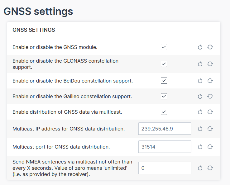
Configuration
In the Configuration Web User Interface via the Advanced Settings, you can configure following settings:
-
Enable the GNSS module, if not done yet.
-
Enable the GLONASS, BeiDou, Galileo as needed.
-
The distribution of GNSS data via multicast is enabled by default.
-
Adapt the IP address for the multicast, if needed.
-
Adjust the sending of NMEA frames as a multicast message by entering the interval in seconds.
Receive GNSS Multicast Messages
To receive the NMEA GNSS strings via Ethernet/IP shared by the device, the socket must join the multicast group.
The strings are raw NMEA sentences that are terminated by \r\n.
The strings include the position data, i.e. latitude/longitude, the number of satellites, the level.
For testing purposes, you can use a tool that listens to the incoming strings, e.g. Packet Sender or implement a listener on your own, see Receiving multicast messages.
Note
Make sure to connect the GPS antenna to the device and place the antenna outside or close to a window.
Note
Make sure that the computer and the device are on the same LAN for testing.
Note
You might need to open the port (by default 31514).
For Windows operating systems, there might be more settings to configure for multicast, e.g. the receiving interface.
eSIM card
All device types are equipped with an integrated eSIM card. On delivery, the eSIM card already has an eSIM profile with all the necessary communication settings.
Note
Potential connectivity loss with custom SIM card
The device cannot establish an online connection to the Proemion DataPlatform when using a customer specific eSIM card and wrong firewall settings at the SIM provider. IP addresses of the DataPlatform may change without prior notice.
- Make sure that the SIM card provider is not using IP address based white-listing for any DataPlatform communication.
- Make sure that - if white-listing is required - the corresponding DNS names are white-listed at the SIM provider's firewall.
Note
On delivery, the device's eSIM card is not yet activated. After registration of the CANlink® mobile 10000, activation of the eSIM card is triggered automatically. Usually this process takes about 15 minutes. In exceptional cases it can take up to 1 working day.
Nano-SIM card
The CANlink® mobile 10000 is equipped with a hinged nano-SIM card slot that is not accessible from the outside. This type is only available as a customer-specific variant, in which the nano-SIM card provided by the customer is already installed and tested at the Proemion factory.
Replace the nano-SIM card only if the device variant supports this feature and follow the procedure described in the Install the nano-SIM card. Use only approved tools and follow the specified instructions. Improper handling may damage the device and may affect warranty coverage.
Note
Potential connectivity loss with custom SIM card
The device cannot establish an online connection to the Proemion DataPlatform when using a customer specific nano-SIM card and wrong firewall settings at the SIM provider. IP addresses of the DataPlatform may change without prior notice.
- Make sure that the SIM card provider is not using IP address based white-listing for any DataPlatform communication.
- Make sure that - if white-listing is required - the corresponding DNS names are white-listed at the SIM provider's firewall.
Note
Potential connectivity loss with custom SIM card
Malfunction due to defective nano SIM may occur.
- Make sure that the specification of the selected nano-SIM card meets the environmental requirements of the CANlink mobile. Refer to Mechanical.
- Ensure that the dimension of the selected nano SIM is according to form factor 4FF.
Note
If a larger quantity of the CANlink® mobile 10000 with a specific nano-SIM card is required, please get in touch with your responsible sales contact person. A separate order number will then be created.
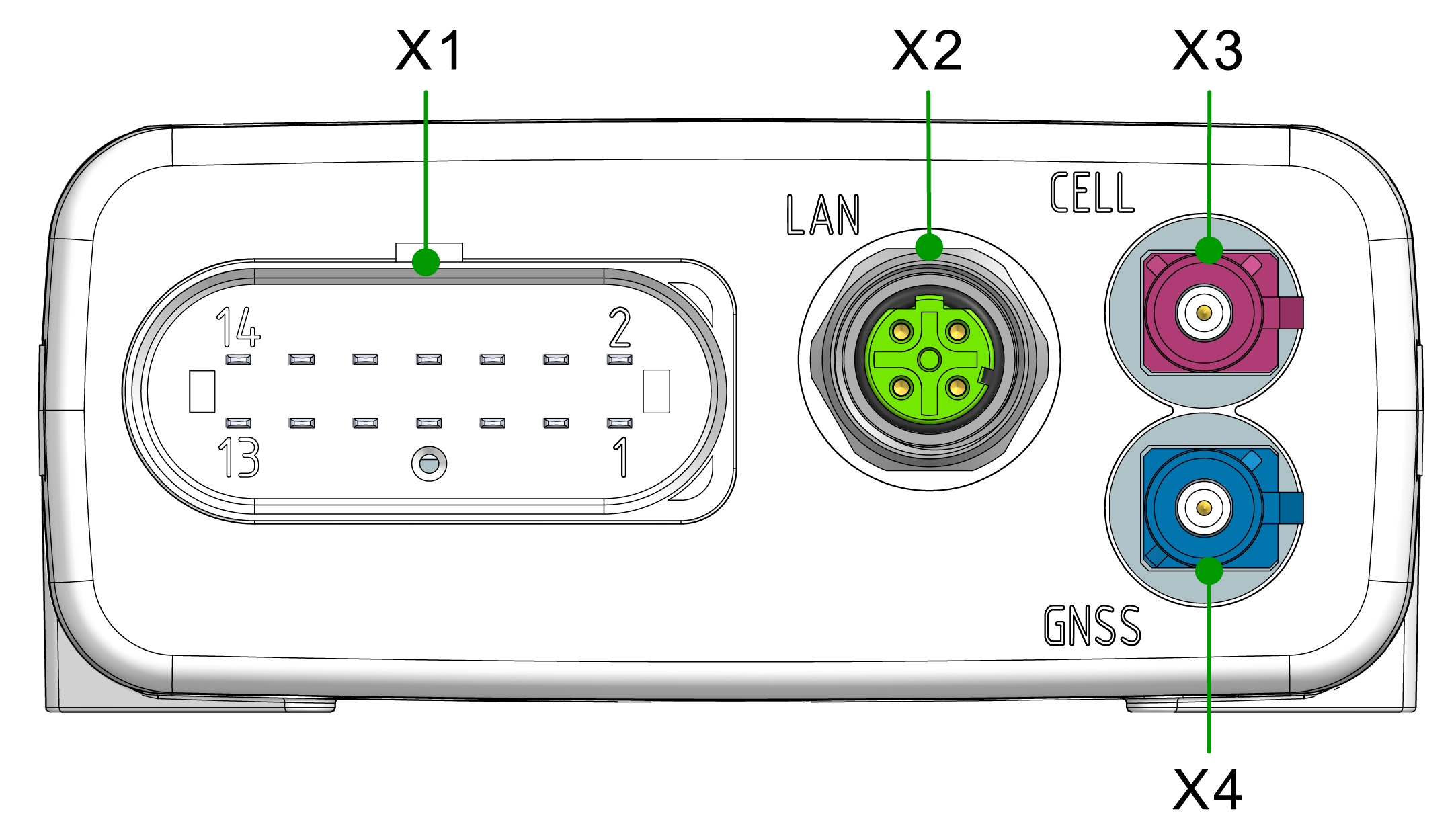
Connectors
The device is equipped with the following connectors:
- X1 - main plug connector
- X2 - Ethernet, LAN
- X3 - cellular antenna connector
- X4 - GNSS antenna connector
Note
Mating Cycles According to the manufacturer's information, the connectors are equipped for the following minimum number of mating cycles:
- Main plug connector: 10 cycles
- Fakra plug: 100 cycles
- Cellular Antenna Port: 100 cycles
- Ethernet connector: 100 cycles
If the minimum number of mating cycles is exceeded, individual parameters could lie outside those in the specification; meaning, the mating cycles can be carried out without quality problems at least for the minimum numbers of mating cycles.
The basic function of the connectors remains intact.
Please be aware that the process of the CANlink mobile system integration is not designed for a high number of mating cycles.
Ideally the device is configured with an adapter cable from the Launch Kit in the first instance and in the second step installed and cabled within the machine.
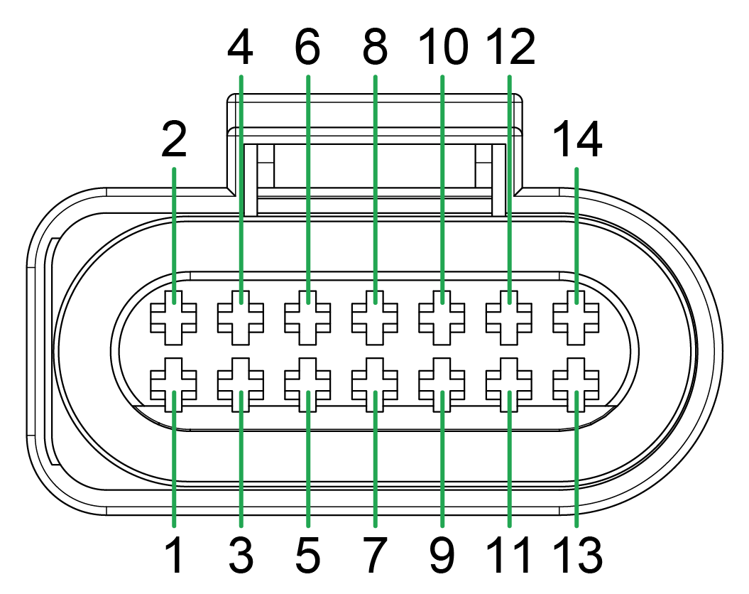
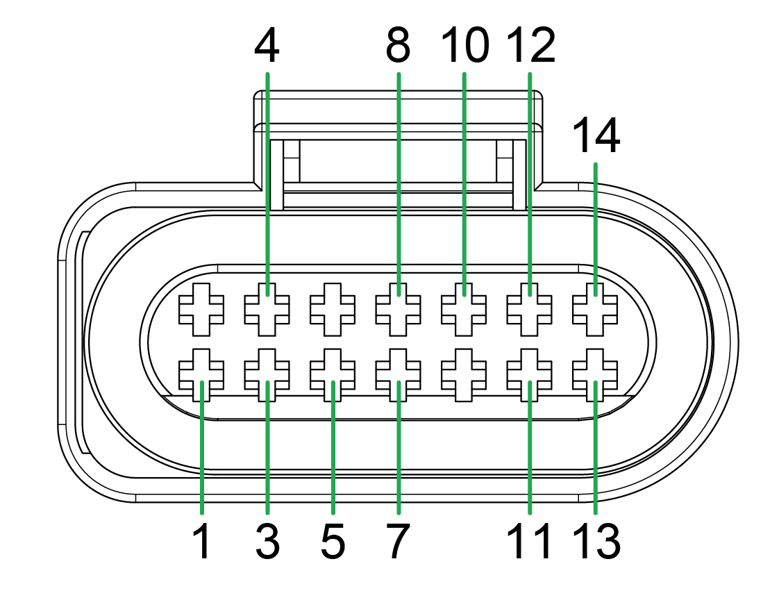
X1 - Main Plug Connector
Use the main plug connector to connect the device to the CAN bus and supply it with power. The I/O signals are integrated in the plug connector.
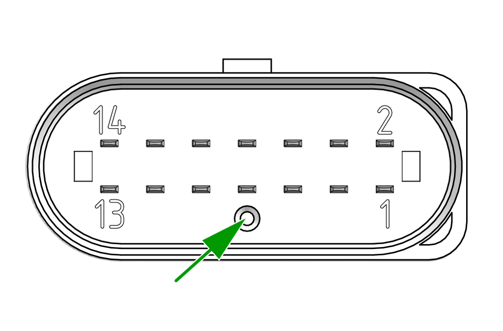
Note
The main plug connector contains a reset button. The Reset button is used to reset and thereby reboots the device, see Reset Device.
Note
The pin assignment shown here can vary depending on the type.
Note
The analog inputs operate in a range of 0 VDC to 15 VDC.
Optionally, you can use the input as a digital input with a maximum voltage of 36 VDC.
The digital output switches to supply voltage on terminal 30 and can only take a maximum load of 500 mA.
Provide an external safeguard if this limit is not ensured by the external terminal 30 power supply.
Input terminal 15 detects "high" from a voltage of 5.5 V and "low" below a voltage of 2.3 V.
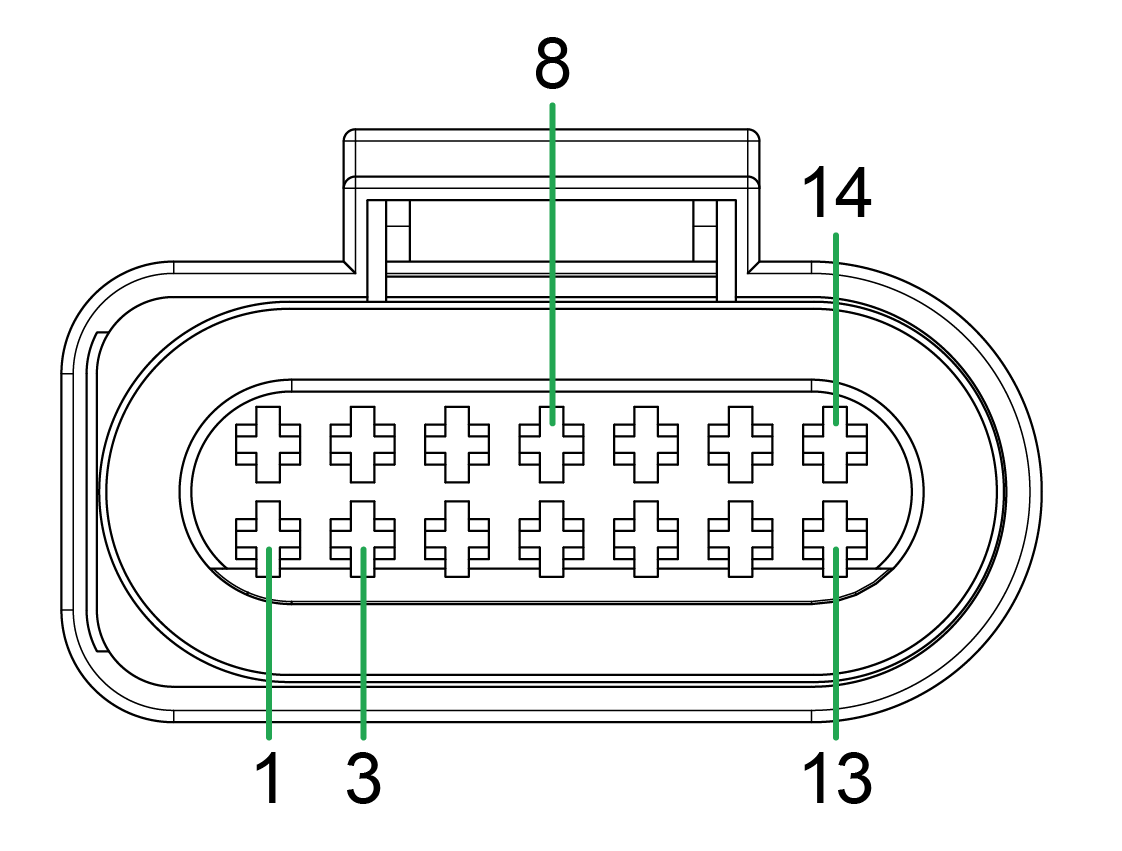
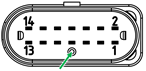
Pin assignment
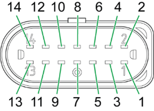
| Pin | Designation | Description |
|---|---|---|
| 1 | Terminal 30 / VCC | Power supply |
| 2 | CAN3-Low | CAN, bidirectional |
| 3 | Terminal 31 / ground | Power supply |
| 4 | Analog input 1 | I/O input |
| 5 | Analog input 2 | I/O input |
| 6 | Analog input 3 | I/O input |
| 7 | Digital output | I/O output |
| 8 | Terminal 15 | Input (ignition signal) |
| 9 | CAN3-High | CAN, bidirectional |
| 10 | Terminal 31 / ground | Power supply |
| 11 | CAN2-High | CAN, bidirectional |
| 12 | CAN2-Low | CAN, bidirectional |
| 13 | CAN1-High | CAN, bidirectional |
| 14 | CAN1-Low | CAN, bidirectional |
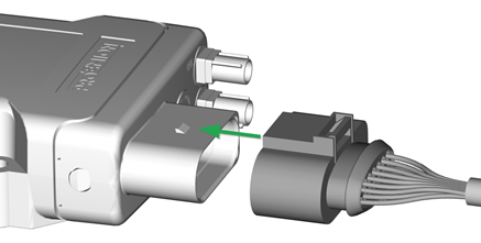
Connect main plug connector
Carefully connect the cable with the main plug connector.
The engagement force of the connector should be up to 86.0N.
When connecting the plug, there must be a clear audible click. Then the lock is correctly engaged.
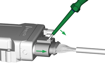
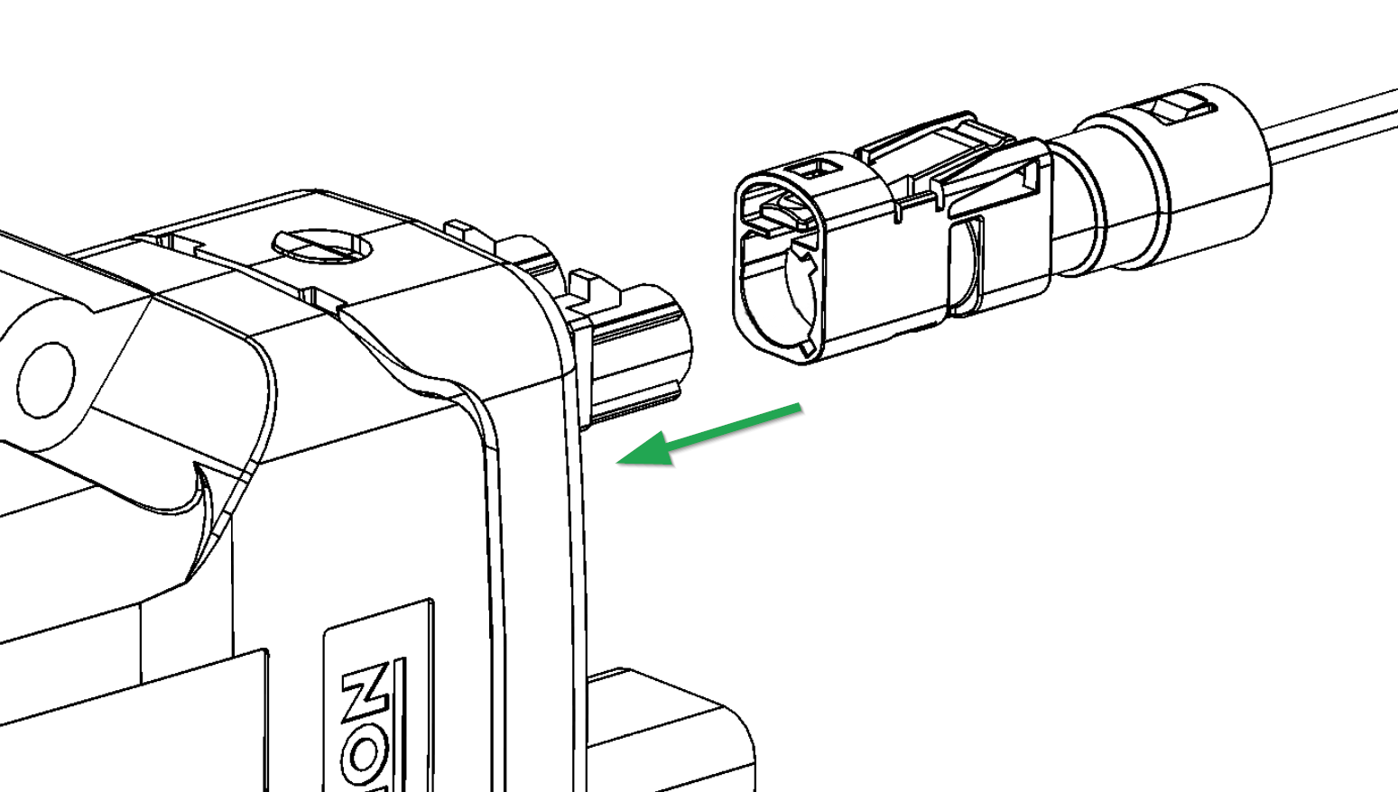
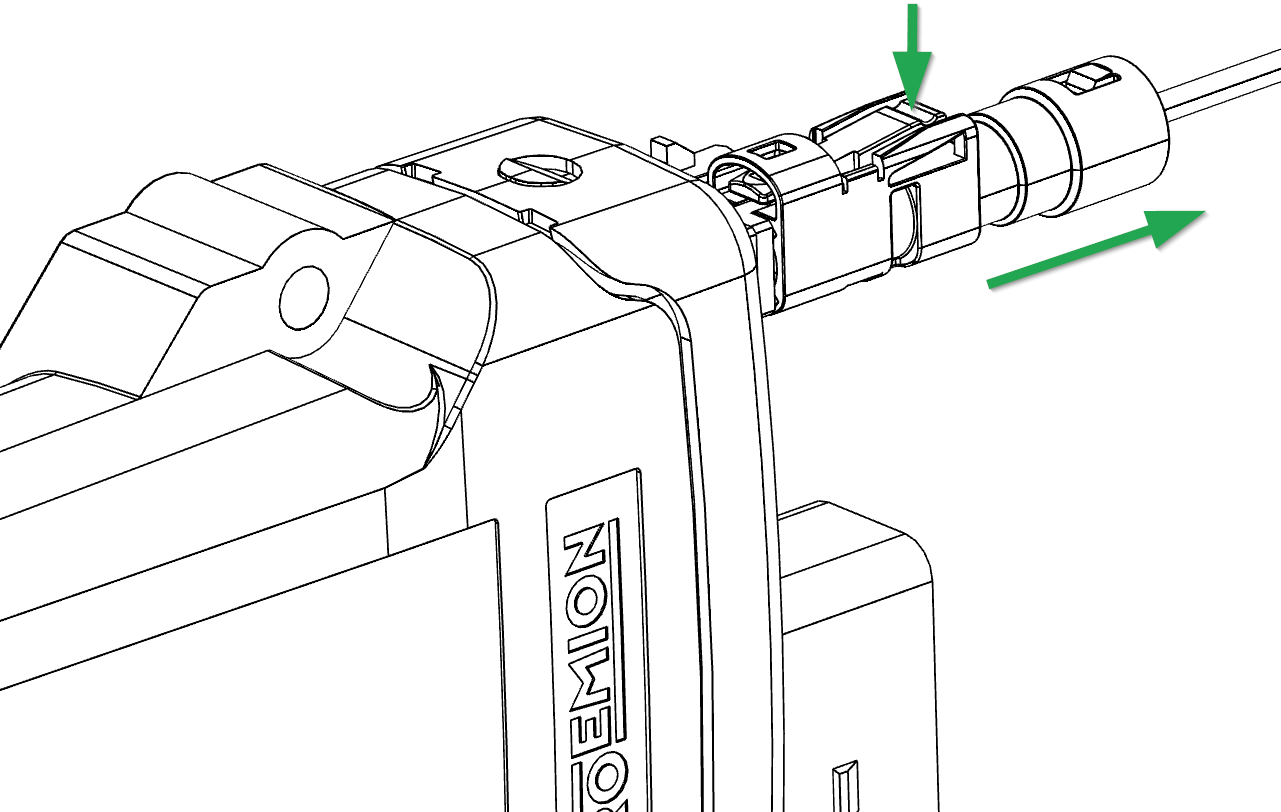
Disconnect main plug connector
To unplug the connection, slightly push the connector housing.
Then actuate the locking arm.
When the clicking is detached, the housing can be taken off.
In case there is no space to disconnect the plug as described, you can use an appropriate flat-blade screwdriver to release the lock (min. 5 mm).
Insert the screwdriver into the tab from above, then gently lever it down and back. At the same time, pull the plug slightly backwards by hand. If you can hear a click, the lock has been released and the connector can be removed.
Note
Risk of property damage
Leakage and contamination due to an increased number of mating cycles and improper disconnecting of the main plug connector.
- Make sure the device is switched off during installation.
- Do not forcibly lever the main plug connector off the device connector.
- Refer to the handling manual from the manufacturer at Automotive Connectors/DeyTrade Connecting - Handling Manual FEP Sealed Connectors.
X2 - Ethernet, LAN
Use the LAN connector to connect the device to a local area network and transmit data directly via the Ethernet connection.
The LAN connector is a standard M12 D-coded threaded connector. The recommended tightening torque is 0.6 Nm ±10%.
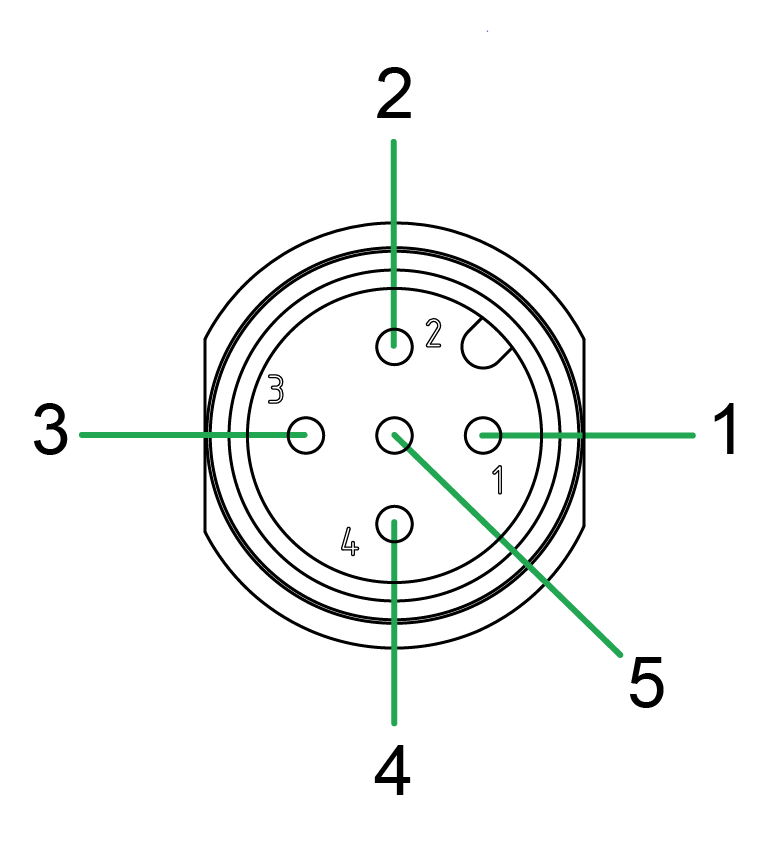
Pin assignment
See the following overview for the pin assignment of the Ethernet connector:
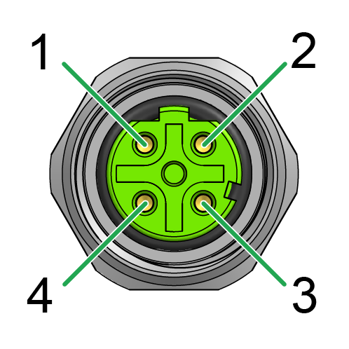
| Pin | Designation | Description |
|---|---|---|
| 1 | TxD+ | Transmit (output) |
| 2 | RxD+ | Receive (input) |
| 3 | TxD- | Transmit (output) |
| 4 | RxD- | Receive (input) |
| Metal thread | Shield | Earth connection |
Note
Connect Ethernet with mating connector IP6K7 and torque 0.6 Nm ±10%.
Note
The Ethernet-SHIELD must be connected to EARTH. This is normally done by use of a shielded cable with the Shield connected to an Ethernet-Switch with Earth-Connection.
Not doing so will result in regulatory non-compliance of the device and possibly failure of the Ethernet connection.
X3 - Cellular Antenna Connector
The cellular antenna connector is used to connect the device to an antenna to receive cellular signals.
Use only matching FAKRA mating connectors (C-coded for GNSS, D-coded for cellular) to maintain the device's IP protection class and electrical safety.
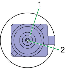
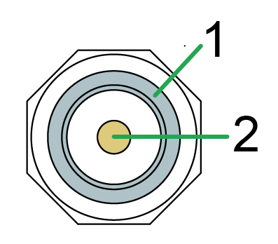
Pin assignment
See the following overview for the pin assignment:
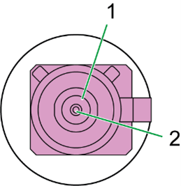
| Pin | Designation | Description |
|---|---|---|
| 1 | Ground | Signal ground /shielding |
| 2 | Signal | Cellular signal |
Note
Do not short-circuit the connector with Terminal 30 voltage.
This may damage the device.
Connect antenna cable
Carefully connect the antenna cable with the coded antenna connector. Make sure that the coding within the socket is matching the coding of the connector. When connecting the plug, there must be a clear audible click. Then the lock is correctly engaged.
Disconnect antenna cable
Use your finger to release the lock by gently levering it down. At the same time, pull the plug slightly backwards by hand.
X4 - GNSS Antenna Connector
The GNSS antenna connector is used to connect the device to an active antenna to receive signals from GNSS satellites.
Use only matching FAKRA mating connectors (C-coded for GNSS, D-coded for cellular) to maintain the device's IP protection class and electrical safety.
Pin assignment
See the following overview for the pin assignment:
| Pin | Designation | Description |
|---|---|---|
| 1 | Ground | Signal ground /shielding |
| 2 | Signal | GNSS signal / supply voltage 3.3 V |
Note
Do not short-circuit the connector with Terminal 30 voltage.
This may damage the device.
For device Variants with dual-band GNSS support, use a compatible active GNSS antenna.
Using an incompatible antenna may reduce positioning performance.
For connecting and disconnecting the antenna, refer to Connect antenna cable and Disconnect antenna cable.
Indicator Elements
Two LEDs are installed on the front of the device to indicate operation and status.
The LEDs make it possible to recognize the status of the CANlink® mobile 10000 at a glance.
This enables trained personnel, i.e. service technicians, in the field to perform an initial error diagnosis in order to be able to initiate further steps (e.g. detailed search or debugging). Furthermore, the LEDs provide visual feedback when performing an update during the process.
Note
Note that there is also a graphical user interface for updates and configuration.
Note
The LEDs have the colors red, green, and blue.
The following tables show possible LED statuses:
ON LED
The ON LED indicates the power supply status.
There are two states of the ON LED:
-
Fading - the device is in a boot/update process.
-
Static - the device is stable (terminal 30).
| Color | State | Meaning |
|---|---|---|
| - | Off | Device switched off or in sleep mode. |
| White | Static | The device starts (e.g. power supply connected) - only visible for a couple of seconds. |
| Blue | Fading | The device is booting. |
| Green | Static | The device switched on, terminal 30 voltage in permitted range. |
| Green | Fading | The device is performing an update while on terminal 30. |
| Yellow | Fading | The device is performing an update while on battery. |
| Yellow | Static | The device switched on is running on battery. |
STATUS LED
The STATUS LED indicates the operating status of the active connections. The various colors reflect the respective priority, from 6 (low) to 1 (high). If several modes are active simultaneously, the STATUS LED always indicates the status with the highest priority (smallest number).
| Color | State | Priority | Meaning |
|---|---|---|---|
| - | Off | 0 | ON LED is also off; |
| the device is switched off. | |||
| The device is in sleep mode; | |||
| The device is booting. | |||
| White | Static | 0 | The device starts (e.g. power supply connected). |
| Green | Fading | 1 | The device initializes the interfaces/service. |
| Red | Fading | 2 | Errors Active. |
| Blue | Static | 3 | The device performs an active diagnostics session. |
| Green | Static | 4 | The device is in normal operation. |
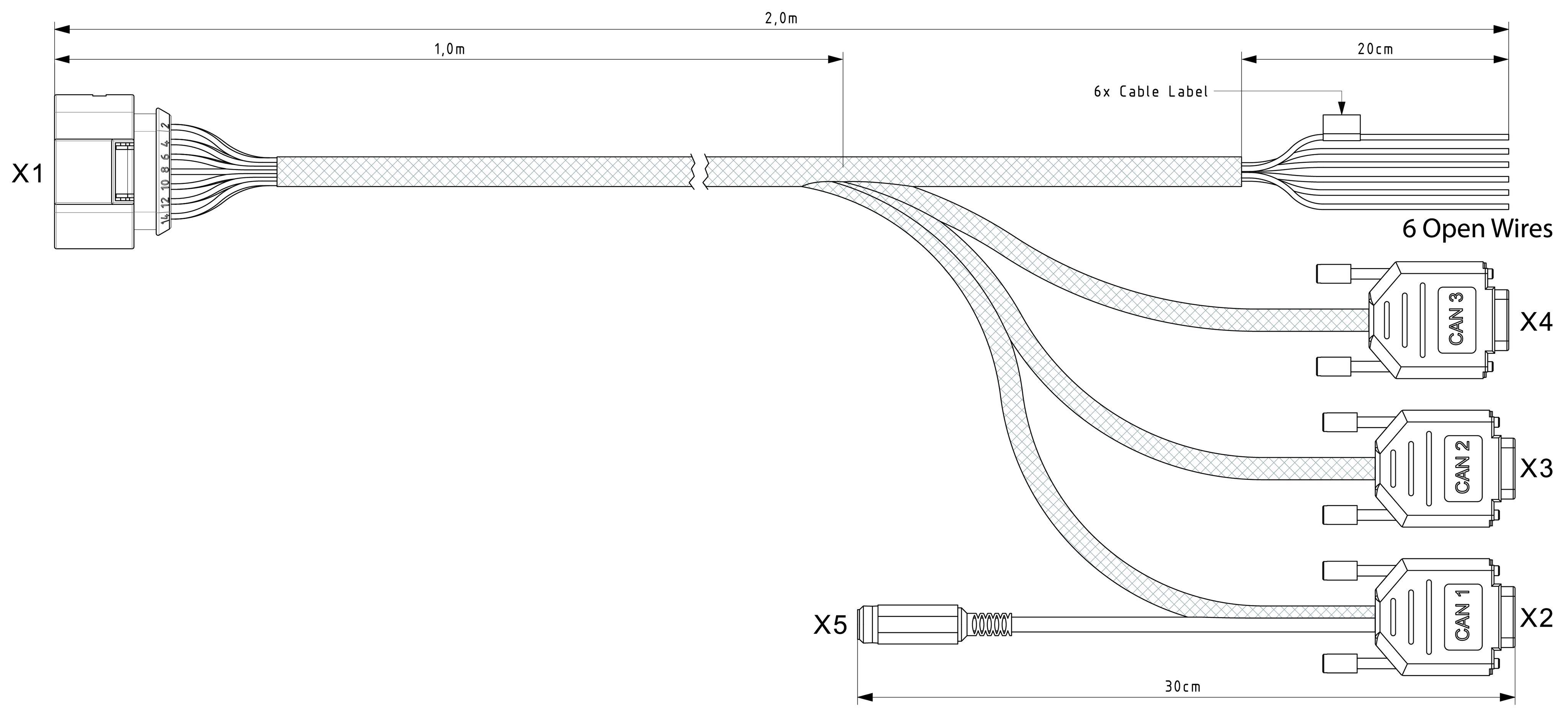
Starter Cable
The cable CLM3600 Starter Cable 6open 3dsub 1pw 2m (part number 136000202), which is also applicable for the CANlink® mobile 10000, must be used for the CANlink® mobile 3600 and CANlink® mobile 10000 variants and is equipped with the following connectors and open individual wires:
- X1: Main Plug Connector
- X2: CAN 1
- X3: CAN 2
- X4: CAN 3
- X5: Power Supply Connector
- 6 Open Wires
X1 - Main Plug Connector
| Pin | Designation | Color | Description |
|---|---|---|---|
| 1 | Terminal 30 / VCC | White | Power supply (steady plus vehicle battery) |
| 2 | CAN3-Low | Brown | CAN, bidirectional |
| 3 | Terminal 31 / ground | Green | Power supply |
| 4 | Analog input 1 | Yellow | I/O input |
| 5 | Analog input 2 | Gray | I/O input |
| 6 | Analog input 3 | Pink | I/O input |
| 7 | Digital output | Blue | I/O output |
| 8 | Terminal 15 | Red | Input (ignition signal) |
| 9 | CAN3-High | Black | CAN, bidirectional |
| 10 | CAN2-GND | Violet | - |
| 11 | CAN2-High | Gray-pink | CAN, bidirectional |
| 12 | CAN2-Low | Red-blue | CAN, bidirectional |
| 13 | CAN1-High | White-green | CAN, bidirectional |
| 14 | CAN1-Low | Brown-green | CAN, bidirectional |
6 Open Wires
Starter cable for main plug connector with 6 Open Wires
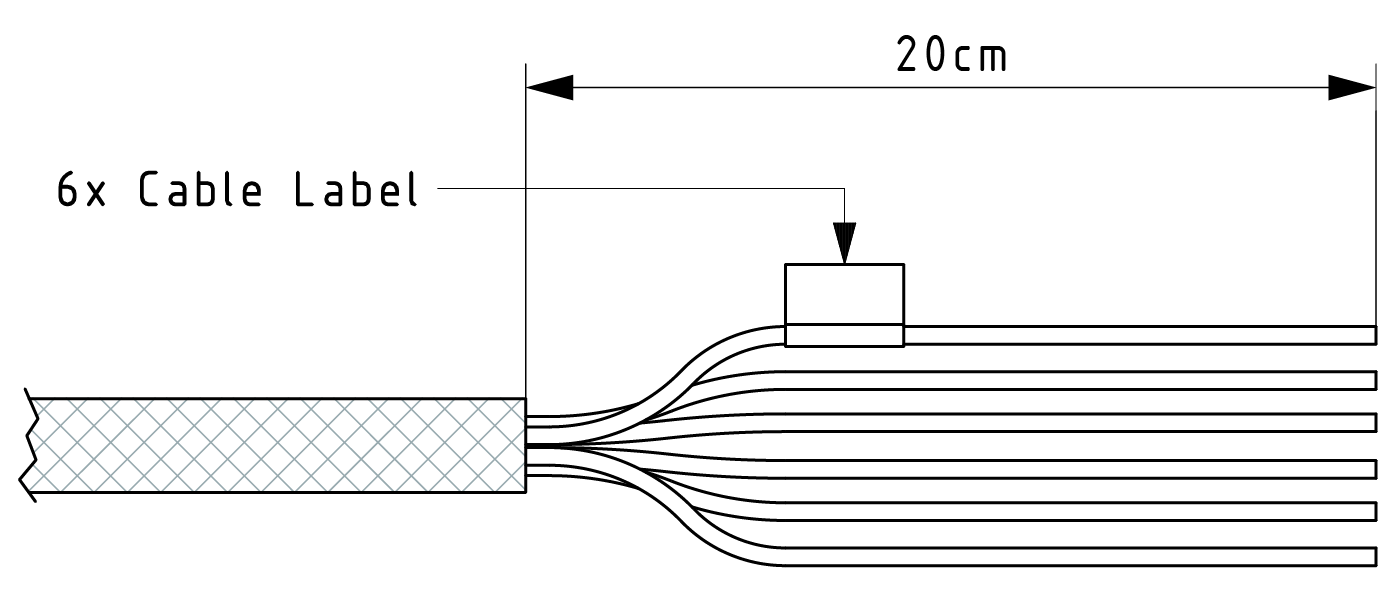
| Designation | Color | Description |
|---|---|---|
| Terminal 31 / ground | Green | Power supply |
| Analog input 1 | Yellow | I/O input |
| Analog input 2 | Gray | I/O input |
| Analog input 3 | Pink | I/O input |
| Digital output | Blue | I/O output |
| Terminal 15 | Red | Input (ignition signal) |
X2 - CAN 1
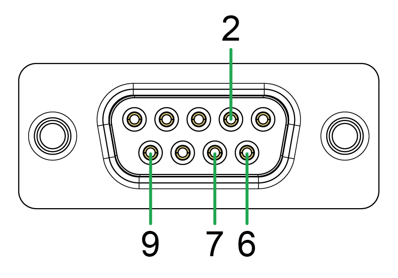
| Pin | Designation | Color | Description |
|---|---|---|---|
| 1 | Not connected | - | - |
| 2 | CAN1-Low | Brown-green | CAN, bidirectional |
| 3 | Not connected | - | - |
| 4 | Not connected | - | - |
| 5 | Not connected | - | - |
| 6 | Terminal 31 / ground | Green | - |
| 7 | CAN1-High | White-green | CAN, bidirectional |
| 8 | Not connected | - | - |
| 9 | Terminal 30 / VCC | White | Power supply |
X3 - CAN 2
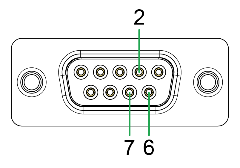
| Pin | Designation | Color | Description |
|---|---|---|---|
| 1 | Not connected | - | - |
| 2 | CAN2-Low | Red-blue | CAN, bidirectional |
| 3 | Not connected | - | - |
| 4 | Not connected | - | - |
| 5 | Not connected | - | - |
| 6 | CAN2-GND | Violet | - |
| 7 | CAN2-High | Gray-pink | CAN, bidirectional |
| 8 | Not connected | - | - |
| 9 | Not connected | - | - |
X4 - CAN 3

| Pin | Designation | Color | Description |
|---|---|---|---|
| 1 | Not connected | - | - |
| 2 | CAN3-Low | Brown | CAN, bidirectional |
| 3 | Not connected | - | - |
| 4 | Not connected | - | - |
| 5 | Not connected | - | - |
| 6 | CAN3-GND | Green | - |
| 7 | CAN3-High | Black | CAN, bidirectional |
| 8 | Not connected | - | - |
| 9 | Not connected | - | - |
X5 - Power Supply Connector
| Pin | Designation | Color | Description |
|---|---|---|---|
| 1 | Terminal 31 / ground | Green | Power supply |
| 2 | Terminal 30 / VCC | White | Power supply |
Adapter Cables
The following adapter cables are applied when replacing old devices.
Adapter Cable to M12, 5-Pin
The Adapter Cable to M12, 5-Pin (part number 136200001).
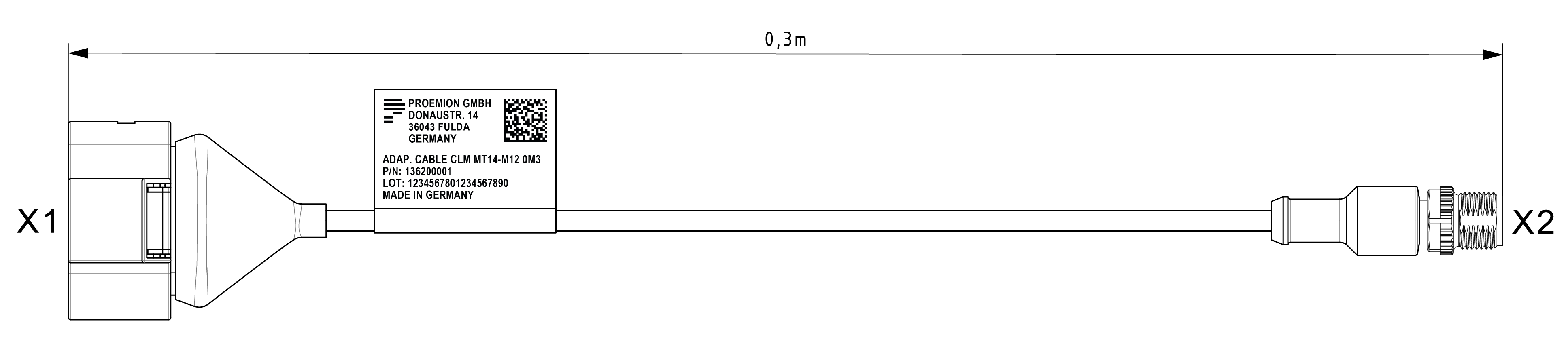
It has the following connectors:
- X1 - Micro-Timer II socket connector, 14-pin, female, code I
- X2 - M12 connector, 5-pin, male, code A
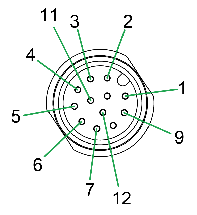
X1 - Micro-Timer II socket connector, 14-pin, female, code I
X2 - M12 connector, 5-pin, male, code A
Adapter Cable to M12, 12-Pin
The Adapter Cable to M12, 5-Pin (part number 136200002).
It has the following connectors:
- X1 - Micro-Timer II socket connector, 14-pin, female, code I
- X2 - M12 connector, 5-pin, male, code A
X1 - Micro-Timer II socket connector, 14-pin, female, code I
X2 - M12 connector, 5-pin, male, code A
Activation of the Device
Note
For the activation, i.e. provisioning and go-live, a Proemion DataPortal (DataPortal) account is needed.
The CANlink® mobile 10000 device is equipped with an integrated eSIM card. Upon delivery, the eSIM card already has an eSIM profile with all the necessary communication settings.
Before you can use the device, it must be activated via the DataPortal.
Note
The user that wants to activate the device needs at least the permission set (Machine:Admin) and the feature switch (Machine Lifecycle) must be enabled for the user's organization unit.
If this should not be the case, please get in contact with the administrator of your organization or our support team, see Service and Support.
For more information, see the chapters Permissions > Machines Service and Feature Switch in the DataPortal User Manual.
-
Log in to the DataPortal.
-
Go to Settings > Administration > Organization Structure.
-
Select the Machines tab.
-
Select Provision Machine button and follow the instruction in the chapters Provisioning and GoLive in the DataPortal User Manual for activating the device.
Recommendations after Activation
-
Consider that after the go-live, the connection of the device to the DataPortal may take up to 24h. You may access to the device via Ethernet to check the connectivity, see also Configuration Web User Interface.
-
For examining the expected LED colors of the device after the first connection both to the power supply and DataPortal, read Indicator Elements to be able to read the LED colors.
-
It is recommended to enable GNSS also for test devices.
CODESYS Development System
For the CODESYS Development System descriptions, read the CANlink® mobile 10000 Quick Start.
Security Features
The CANlink® mobile 10000 has implemented the following security features.
| Area | Feature | Benefit |
|---|---|---|
| Secure communication - system controller (MCU) | Flash read-out protection and removal of Serial Wire Debug (SWD) interface. | Prevents read-out of code and thereby protects against hacking of the software. |
| Secure communication - system controller (MCU) | Removal of debug functionality. | Removes unnecessary functionality in production. |
| Secure boot - main MPU/MCU (MP1) | Restriction of bootloader to specific devices. | Enhanced security by reducing the devices for booting. |
| Secure communication - main MPU/MCU (MP1) | Peripheral isolation of interfaces. | Enhanced reliability. |
| Secure boot - main MPU/MCU (MP1) | OTP lock (closing the device) and PKH check for trusted boot chain, i.e. check of signed software. | Enhanced security by booting only verified software and thereby preventing the installation of malware. |
| Secure boot - main MPU/MCU (MP1) | Trusted boot chain for verifying software up to the second stage bootloader (SSBL). | Implements basic secure boot by securing it up to (including) the SSBL. |
| Main MPU/MCU (MP1) | Disable JTAG port for MP1. | Prevents physical attacks on the device. |
Reset Device
You may reset the device manually via the hardware button which is placed under the main plug connector, see Device Elements.
A manual reset of the device is used to disconnect it completely from any power supply, in order to reset to the standard configuration of the respective firmware variant. This might be useful, for example, when the access to the device got lost due to a misconfiguration of the Configuration Web User Interface during testing.
Note that remote resets or via the Configuration Web User Interface are not enabled.
Note
Make sure that the device was connected to a power supply for ~30 min before removing the main plug.
Note
Note that the device functions will be severely restricted due to device reset and, therefore, only trained personnel should carry out a device reset. Consider to back up your data before a device reset as all logged data is deleted from the device memory.
To reset the device, proceed as follows
Press the Reset button on the main plug connector, see following image, using a suitable tool (1 mm diameter) with the reset duration for the different modes described in the table below:
Switching to a new reset mode is indicated by the ON LED. The STATUS LED is partially illuminated and therefore imitates the ON LED in a slightly darker tone.
| Press Duration | Reset Mode | LED indicator |
|---|---|---|
| t < 5s | Power Reset (disconnect internal battery) | LEDs blink red in a 95/5 period. |
| 5s < t < 10s | Reset the Bridge (only for models with Wi-Fi module) or Ethernet network settings to factory configuration | LEDs start blinking in a 50/50 period. Once 10 seconds are reached the LEDs go off. |
| 30s < t < 40s | Reset to factory settings/configuration | LEDs start blinking in a 25/75 period. Once 40 seconds are reached the LEDs go off. |
| t > 45s | Start Recovery Mode Recovery mode is currently only relevant for Proemion. It allows the CANlink® mobile 10000 to receive a completely fresh firmware installation even if the device refuses to boot. A power reset (t < 5s) allows the CANlink® mobile 10000 to boot normally (and exit recovery mode). |
LEDs start blinking in a 5/95 period when holding the button for more than 45 seconds. Once 100 seconds are reached the LEDs go off. |
You can cancel the reset in the periods between resets. If the reset button is released during this time, the button press is ignored and the device remains in its starting state.
Recovery Mode
The CANlink® mobile 10000 includes an operating mode that supports recovering the device. Once the CANlink® mobile 10000 entered the Recovery Mode both LEDs are static red.
The Recovery Mode can be started manually by the user or automatically in the event that the system is no longer in a healthy/sane state.
While the Recovery Mode is active the device does not run the main application and most of the default functionalities are not operational. The device cannot go online and is not available remotely.
Entering Recovery Mode
There are two scenarios the CANlink® mobile 10000 switches into the Recovery Mode.
-
Initiated by the user by pressing and holding the reset button below the main plug for at least 45 seconds.
See: Reset Device
-
The CANlink® mobile 10000 repeatedly fails to start the main application.
-
With the latest firmware version the CANlink® mobile 10000 attempts to start the main application 10 times per boot partition before considering the boot impossible, see note below.
-
The CANlink® mobile 10000 judges a boot successful if all services are fully operational which can take up to 45 seconds.
-
Note
The CANlink® mobile 10000 has two boot partitions for fallback mechanims. With the latest firmware version the device performs 10 boot attempts per boot partition. Factory devices come with one prepared boot partition the second one is empty. In this case the device will only attempt to boot 10 times before switching into the Recovery Mode. Once the user has performed a new firmware update both boot partitions are in use and the device performs a total of 20 (2*10) boot attempts before switching into the Recovery Mode.
Firmware versions < 2.x.x
For firmware versions < 2.x.x CANlink® mobile 10000 only attempts to start the main application 3 times per boot partition before considering the boot impossible.
Exit the Recovery Mode
The Recovery Mode initiated manually via the reset button can be exited by performing a Power Reset via the reset button of the CANlink® mobile 10000.
Note
This requires the user to press the reset button below the main plug for not longer than 5 seconds. A simple power cycle of the CANlink® mobile 10000 is considered as not reliable. Especially on devices equipped with an internal battery.
If the Recovery Mode was entered because of too many failed boot attempts the system is classified as damaged and a manual recovery is required. The CANlink® mobile 10000 remains in this mode until its recovery.
Recover the CANlink® mobile 10000
Please contact Service and Support for further steps to recover your CANlink® mobile 10000 in case you are facing a broken system.
Remote Machine Tunnel
The Remote Machine Tunnel feature allows secure remote access to machine components that are connected to the same Ethernet network as the CANlink® mobile 10000. This includes remote access to the CANlink® mobile 10000 itself.
Since the CANlink® mobile 10000 supports the CODESYS EdgeGateway service, it can also be used remotely to access other CODESYS-compatible devices on the same local network. The CODESYS EdgeGateway service is disabled by default and must be enabled via the device configuration.
For detailed information on how to configure the Remote Machine Tunnel feature in the DataPortal read the section Remote Machine Tunnel in the DataPortal user manual.
Default Interfaces and Services
This section provides an overview of all network interfaces and services that are enabled/disabled in the factory default configuration of the CANlink® mobile 10000. It describes:
- All network interfaces that are exposed/hidden upon initial setup, and
- All services accessible/inaccessible through these interfaces by default.
The purpose of this section is to offer transparency into the initial communication capabilities of the CANlink® mobile 10000. This supports secure integration into managed environments and the application of organization-specific security policies.
Default Interface States
| Interface | Default State |
|---|---|
| CAN | Disabled |
| Cellular | Enabled |
| Ethernet (DHCP Server) | Enabled |
| WiFi | Disabled |
| GNSS | Enabled |
The CAN interfaces are managed by the CODESYS application and are automatically enabled/disabled based on operational requirements. All other network interfaces can be configured, enabled, or disabled via the Configuration Web User Interface.
Default Service States
| Service | Port(s) | Protocol(s) | Can be disabled |
|---|---|---|---|
| Web Server (WebUI, JSON API) | 80, 443 | TCP | No |
| DHCP Server on Ethernet | 67 | UDP | Yes |
| Domain Name System on Ethernet | 53 | UDP, TCP | Yes (DHCP Server) |
| Network Time Protocol Client | 123 | UDP | Yes |
| Link Local Multicast Resolution | 5355 | UDP | No |
| Multicast DNS | 5353 | UDP | No |
Getting Started
Connecting the Device
Connecting the Device
When connecting the device to a PC, it may be helpful to use a USB-to-Ethernet adapter, as many PCs have only a single Ethernet port. It is also recommended to connect the device via Wi-Fi if a wired connection is not available.
To protect the device from damage and data loss, a correct wiring and configuration of the power management settings is mandatory. The main purpose of the power management settings is that the device has a safe shutdown before the supply voltage (terminal 30/31) is disconnected.
Warning
Overload damage due to malfunction.
Risk of severe or fatal injury.
- To limit power in the event of malfunction, secure the DC power supply circuit during installation with an external 2 A fuse.
Risk of property damage
- The device must be installed, connected, and commissioned by a qualified technician.
- Ensure the power supply is disconnected before connecting the device.
- Only use components from the launch kit or the accessories supplied. Refer to chapters Launch Kit and Software and Accessories.
If you have any questions or anything is unclear, please contact our support before getting started. See Service and Support.
Note
Device defect due to power failure.
Destroyed hardware component on the device. Repair not possible.
Destroyed file system on the device. Repair by Proemion necessary.
- Permanently connect terminal 30 to steady power supply (vehicle battery) to ensure that the required power management settings can be applied to the device in the right manner.
- Permanent disconnection from the power supply is only permitted when the device was set to sleep mode before.
- Connect terminal 15 correctly and configure secure switching to sleep mode in the Power Management section of the device configuration.
- Do not disconnect the device from the power supply until it has completely switched to sleep mode (all LEDs off).
Power Supply
The main plug connector supplies the device with power. If you use the power supply unit from the kit, make sure you use the country adapter for your country.
Charging the Battery
Before you use the device for the first time, fully charge the integrated battery using main plug connector cable supplied. See Starter Cable for Main Plug Connector.
Lithium-Polymer batteries have a limited storage time and lifetime.
During storage, the charge level must be kept in certain limits.
The limited lifetime reduces the full charge capacity of the battery after 500 charging cycles to 80% of the rated capacity.
Note
- The integrated battery can only be charged in the limited battery temperature1 range of 0 °C ... +45 °C / +32 °F ... +113 °F.
- Battery operation of the device is only possible in a limited battery temperature1 range of -20 °C ... +60 °C / -4 °F ... +140 °F
1 Due to self-heating of the device, the battery temperature is approx. 15°C higher than the ambient temperature, depending on device TYPE (see Device Elements) and device usage (see Intended Use).
The firmware/software implementation for the battery related device variables is not specified yet.
Install the nano-SIM card
This chapter describes how to properly install the nano-SIM card in the CANlink® mobile 10000 device.
Note
Ensure the device is powered off before proceeding. Observe all ESD protection measures: wear a grounding wrist strap, work on an antistatic surface, and avoid touching any other components on the PCB.
Open the Housing
Open the housing using the CANlink® mobile Opening Tool. For detailed instructions, refer to CANlink mobile Opening Tool manual.
Note
Open the housing only for the purpose of inserting or replacing the nano-SIM card. Use only the approved CANlink® mobile Opening Tool and follow the instructions carefully.
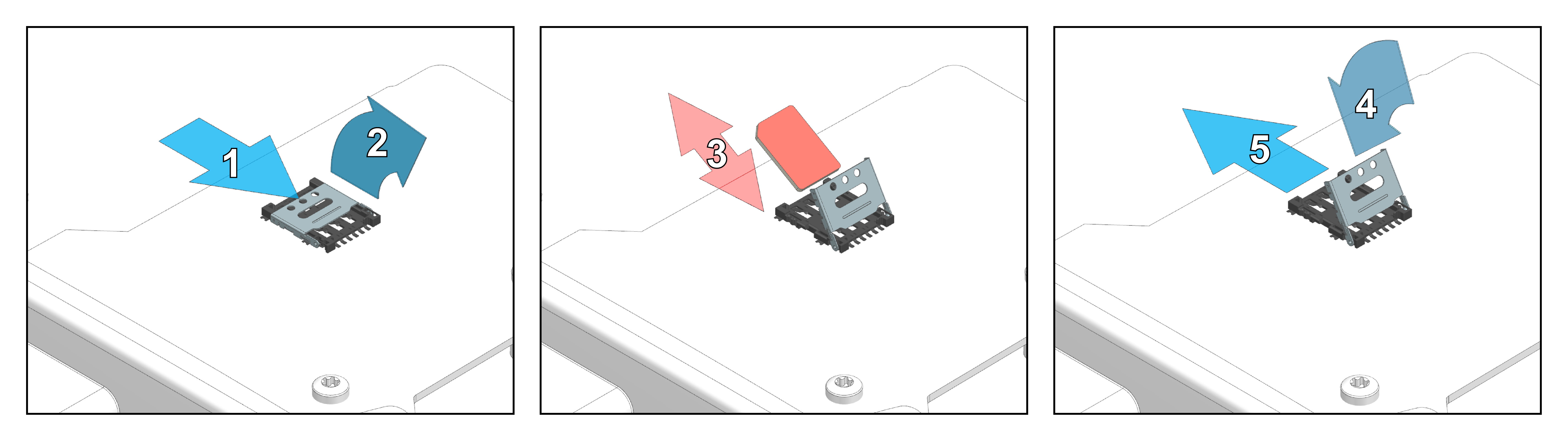
Insert or Replace the nano-SIM card
The following figure shows the steps required to insert or replace the nano-SIM card.
Note
Handle the nano-SIM card with care. Do not force or bend the nano-SIM card during installation.
The nano-SIM card holder is located on the top side of the PCB assembly.
To install the nano-SIM card, proceed as follows:
- Slide the metal shell to unlock the SIM card holder.
- Flip the metal shell open.
- Insert or replace the nano-SIM card carefully. Make sure the chamfered corner aligns correctly with the holder.
- Fold the metal shell back down.
- Slide the metal shell into the locked position until it is securely locked in place.
Close the Housing
Note
Before closing the housing, ensure the nano-SIM card lies flat and is properly seated in the holder.
The housing is equipped with two click fasteners, which must be closed separately and sequentially. Apply force only at the designated pressure points. These pressure points are located at the outer edge of the cover on the short sides, aligned with the click fasteners. Closing the housing requires a higher level of force at these pressure points.
Cellular and GNSS Antenna
The CANlink® mobile 10000 devices are equipped with external antenna ports for mobile radio and GNSS signals.
The antenna ANT LTE GNSS DA 3M0 FAKRA-D FAKRA-C FAR (part number 157000121) and ANT LTE GNSS DA 3M0 FAKRA-D FAKRA-C FA (part number 157000109) features a port for mobile radio signals (FAKRA-D - violet) and a port for GNSS signals (FAKRA-C - blue).
The Cellular and GNSS antenna (part number 157000121) has two separate connectors:
- Cellular (FAKRA-D, violet)
- GNSS (FAKRA-C, blue)
Cellular Antenna Connector
Connect the antenna's FAKRA-D plug (violet) to the device's FAKRA-D port (violet).
- Only use antennas with the maximum gain specified in the Technical Data.
GNSS Connector
Connect the antenna's FAKRA-C plug (blue) to the device's FAKRA-C port (blue).
-
Only use active GNSS antennas with:
- LNA
- Gain max. 25 dBi
- Voltage 3.3 VDC
- Current max. 40 mA
Installation Notes
- Mount the GNSS antenna so that it is level with the horizon and has a clear view of the sky.
- Do not extend antenna cables.
- Ensure the minimum bending radius of the antenna cable is at least 8 times the outer diameter.
- Use only antennas supplied as Proemion accessories.
Switching the Device On/Off
The device does not have an on/off switch.
The device can be powered on by each of the following conditions:
- Terminal 15 level is high
- Detection of a specific Acceleration Sensor Wake-up Force
- Cyclic wakeup time is elapsed
PC connection
When connecting the device to a PC (e.g., for configuration with the Proemion Configurator ) make sure that the ignition input signal (Terminal 15, red wire) is supplied with a voltage of at least 6 V (typically 12 V).
Without this signal, the device will not start completely, and the Proemion Configurator may not display full device information in the Node Scan.
If Terminal 15 is not connected, ensure that Enable sleep mode in the Power Management configuration is disabled via the Configuration Web User Interface to prevent automatic shutdown.
Note
Device defect due to power failure.
Destroyed hardware component on the device. Repair not possible.
Destroyed file system on the device. Repair by Proemion necessary.
- Permanently connect Terminal 30 to steady power supply (vehicle battery) to ensure that the required power management settings can be applied to the device in the right manner.
- Permanent disconnection from the power supply is only permitted when the device was set to sleep mode before.
- Connect Terminal 15 correctly and configure secure switching to sleep mode in the Power Management settings via the Configuration Web User Interface.
- Do not disconnect the device from the power supply until it has completely switched to sleep mode (all LEDs off).
Battery low voltage.
In the case of variants with an internal rechargeable battery and no Power Management configuration, the device continues to operate in Battery mode until it is switched off via the low voltage disconnect function.
- Permanently connect Terminal 30 to steady power supply (vehicle battery) to ensure that the required power management settings can be applied to the device in the right manner.
- Connect Terminal 15 correctly and configure secure switching to sleep mode in the Power Management settings via the Configuration Web User Interface.
In case the proper settings are not made, you can switch the device off via the Reset button:
Disconnect the main plug connector. Actuate the inlying button using an appropriate tool with a diameter of approx. 1mm.
The LEDs and the device are switched off. Please be aware that this is an emergency procedure with the risk of device defect due to power failure!
Mounting
Below you will find instructions on how to mount the device.
To ensure the housing provides proper fire protection and to achieve the best possible reception of radio signals, make sure you install the device in the correct position.
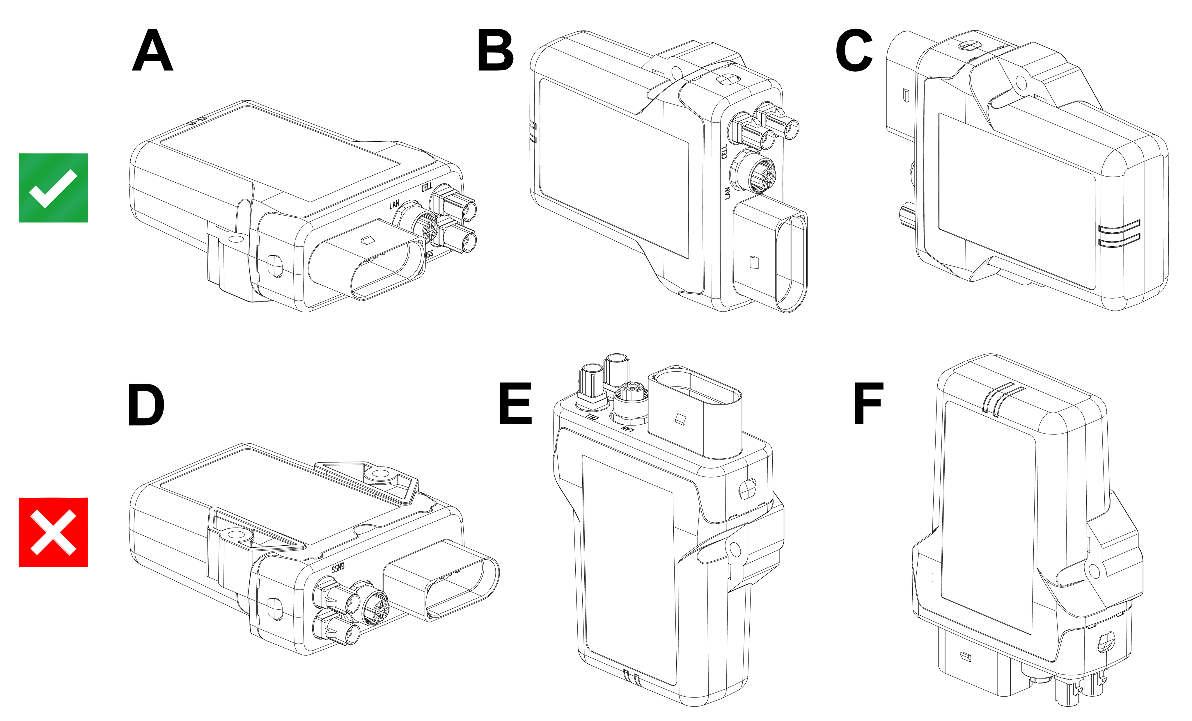
Mounting Orientation
The view elements of the two LEDs on the device do not comply with the flammability class required for a fire protection housing.
Note
Fire protection of the housing is only guaranteed in the installation positions shown in figures A, B or C or F.
Note
Please note that fire protection is not guaranteed in the installation positions shown in figures D and E.
Note
The mounting position F fulfills the requirements of a fire protection enclosure. But is not recommended due to possible liquid ingress.
Note
To avoid water ingress, please make sure that the mounting orientation of your device is either as shown in figure A, B or C.
Note
Risk of property damage.
- The device can be mounted with the plugs pointing to the left or right. Mounting with the plugs pointing up is not permitted. Mounting with the plugs pointing down is not recommended due to the risk of water ingress.
- Only mount the device in one of the installation orientations shown in this chapter.
- The device is protected against mechanical impacts according to class IK07 (IEC62262 impact energy 2 joules). To achieve a higher class, you must provide external protection when installing the device
Functional conditions
Consider the electrical conditions described below and also in the Technical Data including the overload protection.
Antenna Positioning
For optimal reception of Bluetooth, Wi-Fi®, and cellular signals, ensure that radio waves are not obstructed by housing parts or surrounding objects.
Ensure that radio signals are not obstructed by labels, objects, or surrounding structures.
- Only mount the device in the installation position shown in Mount the Device.
- Choose a mounting location with minimal obstructions to ensure reliable communication.
- Do not apply additional labels to the device, as certain materials may significantly reduce signal quality.
- Do not modify the device or its surroundings in a way that affects antenna performance.
- The system integrator is responsible for ensuring adequate antenna performance and compliance with applicable regulations.
Antenna spacing
Maintain sufficient distance between antennas to avoid interference.
- The distance between antennas should be greater than 1/4 of the wavelength
- Avoid distances that are multiples of the wavelength
- When using multiple antennas, base the minimum distance on the lowest frequency
Example:
If using GNSS and Wi-Fi® antennas, maintain a minimum distance of 4.8 cm between antennas.
Internal Antennas
Internal antennas are installed inside the housing on the top of the device.
For the best possible reception of GNSS, Bluetooth, Wi-Fi® and mobile radio signals, the device should be mounted in the position shown here.
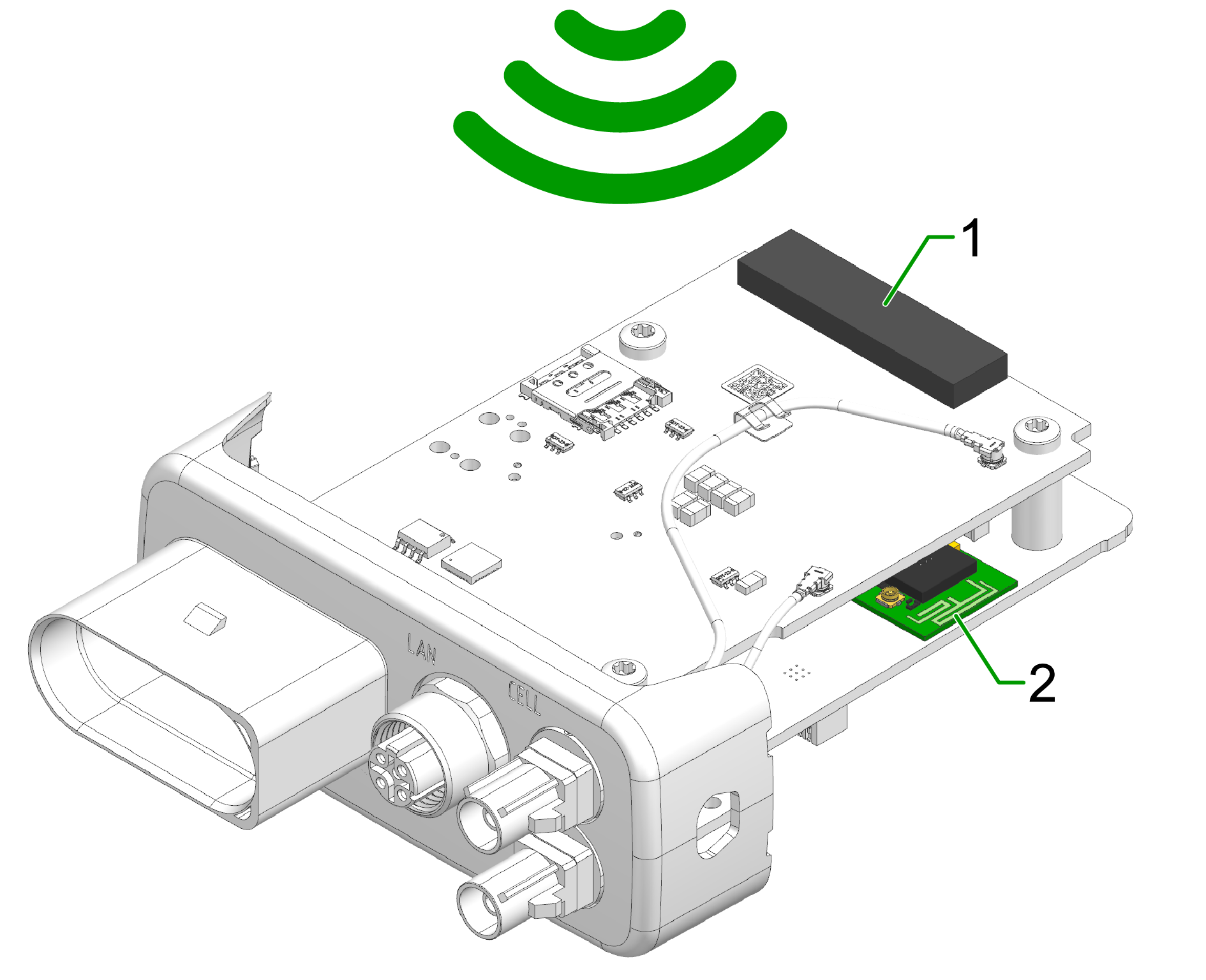
- Diversity cellular antenna
- Main cellular antenna (only for types )
- Wi-Fi / Bluetooth antenna
- GNSS antenna (only for types)
External Antennas
The following information applies to device variants with external antenna connectors.
For information on connector types, pin assignments, and instructions to connect and disconnect the antenna cables, refer to the Connectors chapter.
Refer also to the Safety Instructions for applicable safety requirements.
Antenna installation
Improper antenna installation may reduce cellular communication and GNSS performance.
- Use only approved antennas which are supplied as accessories by Proemion.
- Optimize the mounting position to reduce the distance between the antenna and the device or order an alternative antenna with longer antenna cable.
- Do not extend the antenna cable.
- Ensure that the minimum bending radius of the antenna cables is at least 8 times the outer diameter.
GNSS Antenna
Use only active GNSS antennas with LNA.
For detailed electrical specifications, refer to the CANlink mobile 3600 Datasheet.
For connector details, refer to the GNSS Antenna Interface.
Cable Management
The following chapter describes how to install the cable harness and how to handle custom cabling.
Before starting the installation, read how design the correct electrical connection in Connectors and how to connect the cable to the device in Cables.
Proceed as follows:
Note
Adhere to the following instructions to avoid a malfunction of the device. Problems with the mobile network connectivity can be caused by an insufficient antenna setup and bending radius of the cables.
By that there is a risk of damaged cables and also water penetration due to incorrect assembly of the cable and missing sealing.
-
Assemble the cables in accordance with the recommendation of the manufacturer.
-
When mounting the device, please make sure that there is an adequate bending radius of the cables.
-
Ensure that there is a minimum bending radius of 8 times the outer diameter of the antenna cables.
-
Install strain reliefs for the cables.
-
Fasten the cable harness with a suitable strain relief near the main plug connector in order to avoid the transmission of any tension, strains or vibrations to the main plug connector and the housing.
-
Protect and fix the cables within the machine.
Connectors
For the connection to the device, several connectors are provided that require certain handling of the cables. The main chapter Connectors provides detailed information on connector type, pinning, etc. for the following connectors:
- X1 - Main Plug Connector
- X2 - Service Interface only for CANlink® mobile 3600
- X3 - Cellular Antenna Connector (mobile radio antenna connector)
- X4 - GNSS Antenna Connector
Cables
Different types of cables are used for the mentioned connectors. The following cables are supplied by Proemion:
- Starter cable for main plug connector only for CANlink® mobile 3600; covering also: Starter cable for main plug connector, individual wires open
- USB Connector Cable - Diagnostic only for CANlink® mobile 3600
The chapter Cables provides more information on the different cables and their cable ends.
Tip
Refer to Custom Cable for Main Plug for information on how to integrate the device into a custom cable harness on the machine.
Custom Cable for Main Plug
When creating a customized cable harness for the system integration of the CANlink® mobile 3600, CANlink® wireless 4000, or CANlink® mobile 10000, some important recommendation for the setup of the main plug connector and cable must be considered.
It is recommended to use the connector components included in the Connector Kit, see Launch Kit to create a custom cable harness.
Note
Risk of property damage.
- This chapter contains some important advices. Please follow the instructions from the connector manufacturer and general rules for creating and protecting cable harnesses.
Note
Risk of property damage.
Water penetration due to capillary action of the cable strands.
- Ensure that both ends of the cable strands are sealed and assembled in the correct manner and in accordance to the manufacturer's specifications.
| Product | Recommendation |
|---|---|
 |
For the cable assembly it is essential that the instructions from the handling manual of the connector supplier are followed. Especially the main sealing, wire sealing and dummy plugs must be installed in the right manner. Refer to Automotive Connectors/DeyTrade Connecting - Handling Manual FEP Sealed Connectors. |
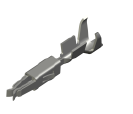 |
Use only the recommended tooling for machine processing. Refer to Connector Kit Datasheet. It is recommended to use tinned contacts. This corresponds the material of the pins |
 |
Use the wire sealing which fits to the outer diameter of the used wires |
 |
Cover the unused contact sockets with dummy plugs to protect the connection from dust and humidity |
Protective Cover
Protect the connector and the cable with sufficient covers and cable tubing:
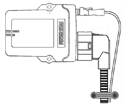
Warning
The following parts are not distributed by Proemion and can only be requested from the manufacturer with a minimum order quantity of 500 units, see Schlemmer.
The following part numbers from the supplier Schlemmer are recommended for the protective cover: 7807174, 7807207, 7807624:
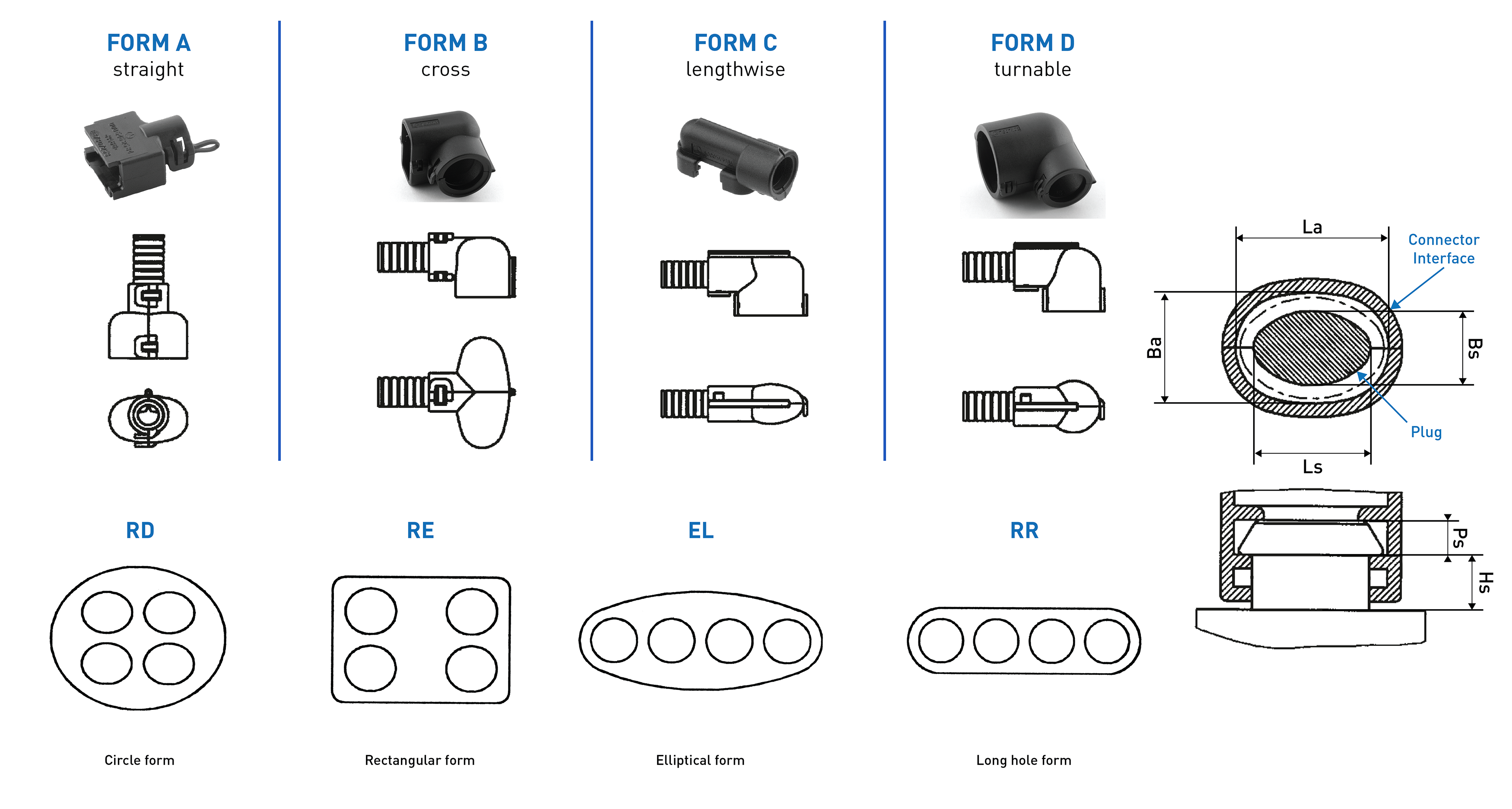
Mount the Device
Tip
Mount the device in such a way that it is not directly exposed to weather conditions, especially rain and direct sunlight as this may influence the ingress protection and thus lead to damage to the device, see also Mounting Orientation.
To mount the device, proceed as follows:
Mount the device directly with 2 socket-head screws (M5) inserted in the mounting holes on the sides and screwed to the mounting surface.
For detailed information on the distances between the holes, see Technical Drawings.
-
The recommended tightening torque for assembly is 2.2Nm +/- 0.3 Nm
-
The mounting is not suitable for hexagon head bolts.
-
An alternative fastening are M5 screws with a head diameter ≤ 12 mm and an internal drive.
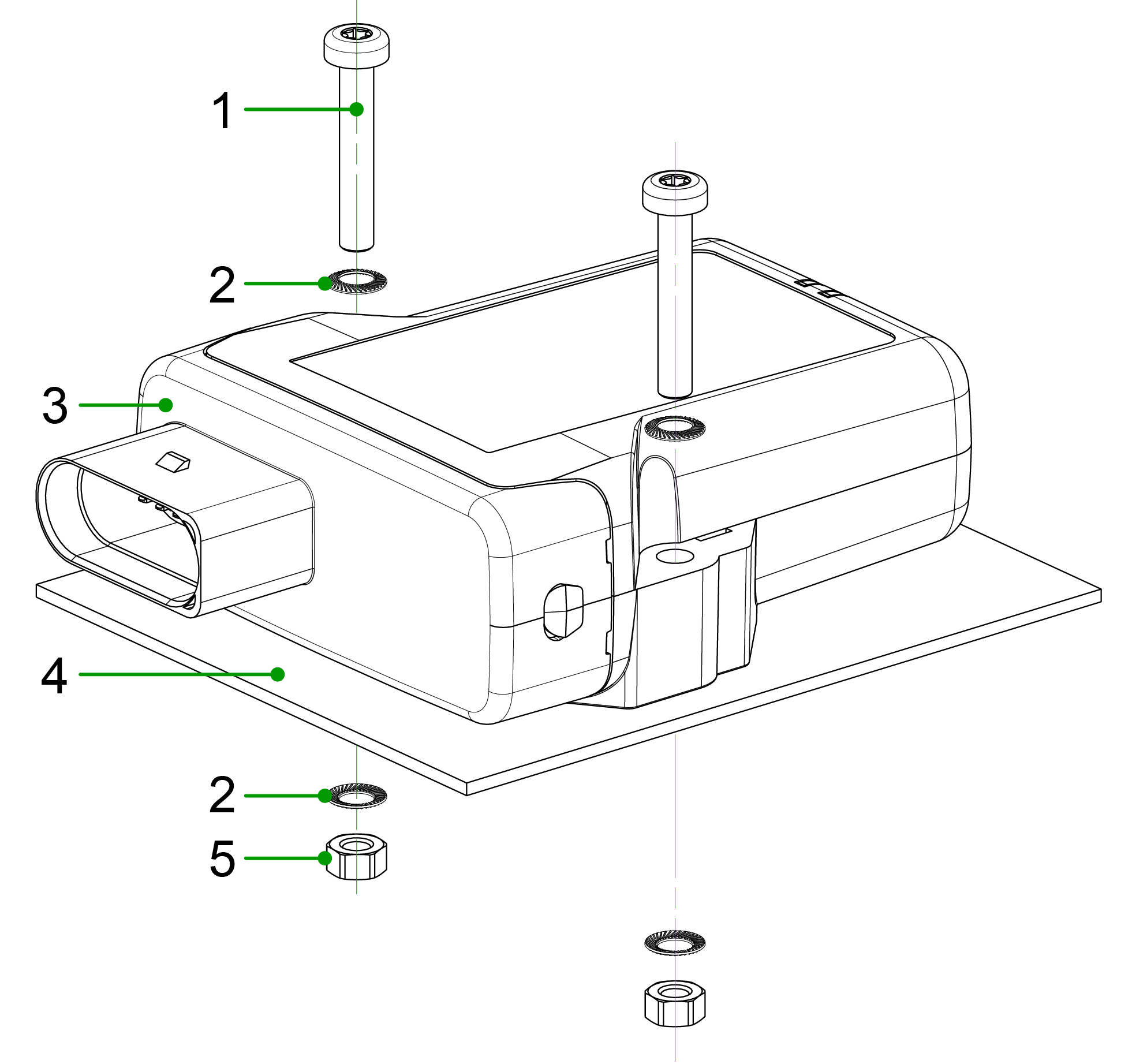
-
Socket-head screw
DIN912 - M5 x 30 mm. The screw should have a length of25 mmplus the mounting plate thickness (up to 5 mmm). For tightening the enclosure, there is a hole on each side with a diameter of 5.5 mm. -
Lock washer
M5, di/D = 5.3/9 mm -
CANlink mobile
-
Mounting plate
-
Hexagon nut
DIN934 / ISO4032 - M5
Note
The mounting material is not included in the scope of delivery. Optionally, you can use the Mounting kit M5 housing GH120x (part number 141000017). The mounting set contains the following components:
- 2 socket-head screws
DIN912 - M5 x 30 mm - 4 lock washers
M5, di/D = 5.3/9 mm - 2 hexagon nuts
DIN934 / ISO4032 - M5
Operation
Configuration Web User Interface
The CANlink® mobile 10000 provides a local web server with a configuration web user interface (configuration web UI) allowing remote maintenance for configuring the network interface, device settings and settings regarding the file upload via the HTTP(S) method.
Access Configuration Web User Interface
Note
In order to access to the configuration web UI, a connection to the device must be established. Make sure that CANlink® mobile 10000 is on and available via the network.
To locally access the configuration web UI of the CANlink® mobile 10000, proceed as follows:
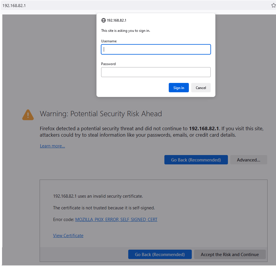
-
In the browser, type in the IP address
192.168.82.1(your local IP address might be a different one).Note
Your browser will show a security warning that you may ignore and "Accept the Risk and Continue".
-
A login window opens where you need to type in the credentials:
- The username is:
admin. - The initial password is provided on the Type Label of the device.
Note
Devices manufactured before August 1st, 2025, use the Ethernet MAC address as the initial password.
- The username is:
It is highly recommended to change the password after initial login, see Security.
In the configuration web UI you can then change between the following configuration menus:
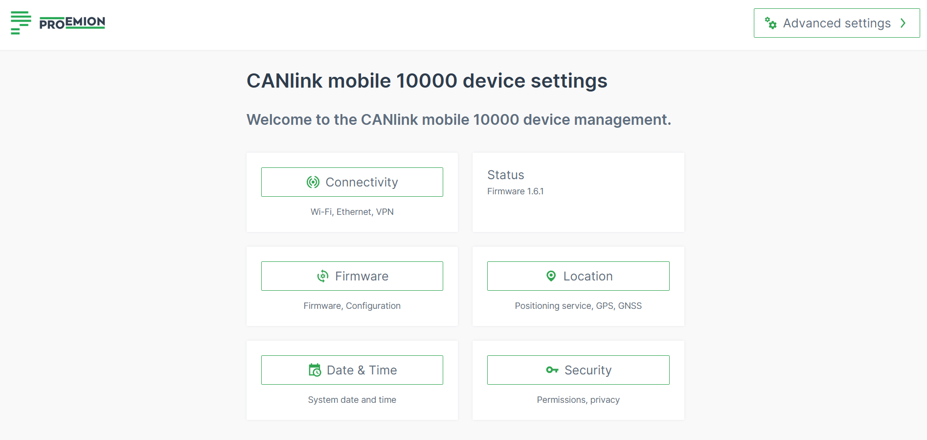
Connectivity
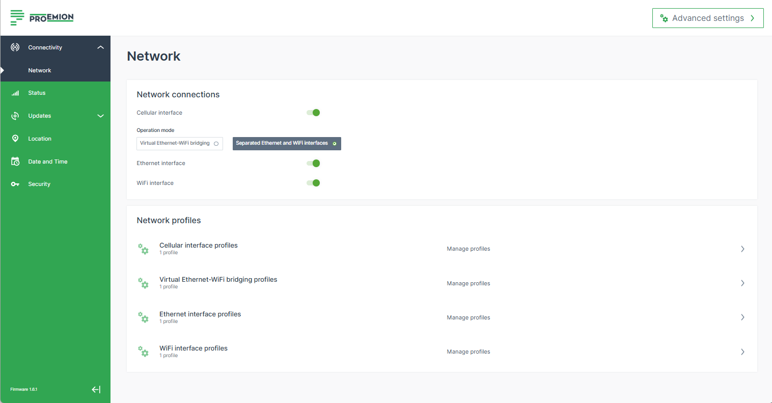
The Connectivity menu provides
- The Network menu for managing the interface/connection profiles for Cellular, Ethernet, WiFi and Virtual Ethernet-WiFi bridging.
- The Remote Machine Tunnel menu for managing the settings for the remote connection functionality.
Find also information on:
- Operation Mode
- Profiles: How to configure Cellular Network Profile, Virtual Ethernet-WiFi Bridging Network Profile, Ethernet Network Profile, WiFi Network Profile.
- How to use Ethernet Access Point with Internet Access, WiFi Access Point with Internet Access and Fallback strategies
Network
In the Network menu you can configure the network interfaces for Cellular (Modem), Ethernet, WiFi and Virtual Bridging Interface to connect the CANlink® mobile 10000 to the DataPlatform.
You can also establish other connections like local direct connections to the device e.g. through WiFi access point.
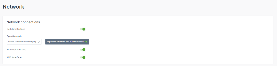
Important
Toggling an interface, en-/disables the connection not only to the DataPlatform, but also the access to the configuration web UI via this interface.
Security Features
The CANlink® mobile 10000 includes traffic control and network monitoring mechanisms as part of compliance with the Radio Equipment Directive (RED), Article 3.3 (EN 18031). These mechanisms help protect the device and connected networks from unauthorized access and different kind of attacks.
In the following sections, the relevant settings are described for adding new profiles. The settings are available for each interface with some dedicated options described in the sections below.
The configuration web UI allows modifying network profiles even if the related operating mode is not active at that moment.
Operation Mode
You can change the Operation Mode to switch between the physical interfaces and the virtual (bridging) interface.
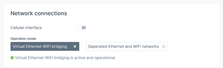
-
Toggle the Virtual Ethernet-WiFi bridging option to activate the virtual (bridging) interface.
Note
When the virtual (bridging) interface is active, the WiFi and the Ethernet interface are always enabled, i.e. cannot be deactivated.
-
Or switch to Separated Ethernet and WiFi networks to separate the individual, physical Ethernet and WiFi interfaces and to work independently of each other (consider adapting the WiFi and Ethernet profiles separately). You may disable an interface.
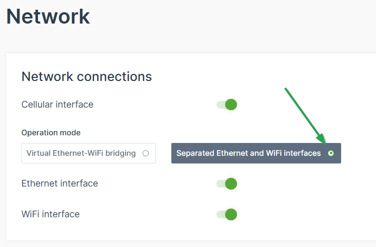
Figure 6: Separated Ethernet and WiFi interfaces Warning
Before switching the mode, make sure to have the profiles configured, otherwise the device might not connect if not configured well, e.g. the profile is still on “auto”.
Profiles
Consider the following conditions for the different profiles:
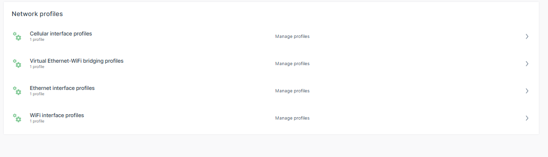
-
Only one profile per interface can be active at a time (even if several are enabled at the same time).
-
For each network interface, Cellular, Ethernet and WiFi, you have a default profile which you cannot delete but only edit.
-
You can add several new profiles with different settings.
To do so, click the plus icon:
Figure 8: New profile -
For each profile of the Cellular, Ethernet or WiFi network interface, you can define the Connection Priority: Enter an arbitrary, positive number - the higher value gives preference.
-
The Connection Priority prioritizes all interface profiles configured by the user for one specific interface.
-
Example: you set up 3 WiFi Interface Profiles for your Home Network, Company Network and Hotspot as fallback. You define the following Connection Priorities:
Home Network: 20
Company Network: 15
Hotspot: 10
If all profiles are set to "Automatically join this network when available" the CANlink mobile will first try to connect to "Home Network", if unsuccessful it will try to connect to "Company Network", if unsuccessful it will start the "Hotspot". This order is just for the WiFi interface. Cellular and Ethernet have their own independent orders of profiles. -
Example:
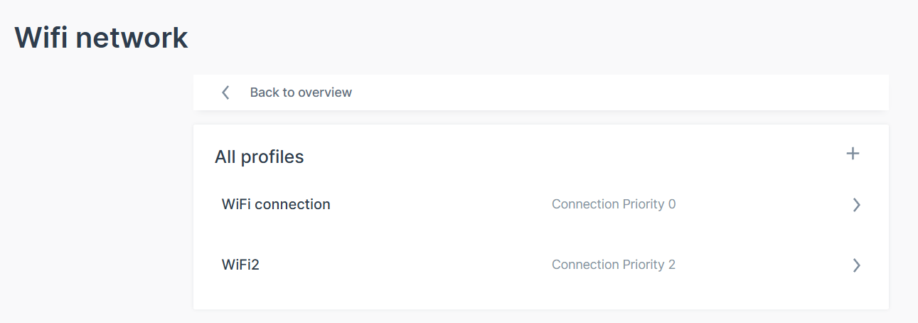
Figure 9: Connection Priority Example Note
For the Routing Metric, the lowest value will be used to route the traffic (e.g. Internet connection).
-
-
Cellular Network Profile
You can use the cellular network profile to establish a DataPlatform connection over the built-in cellular modem.
This can be used to:
- enable bi-directional remote communication with your machines.
- update certain components of the machines via cellular connection.
- use this Internet connection to authenticate to the DataPlatform to exchange relevant data.
- use the cellular modem to share Internet via WiFi and Ethernet, see WiFi Access Point with Internet Access and Ethernet Access Point with Internet Access.
Consider setting the cellular connection as the primary Internet connection, i.e. by changing the Operation Mode or the Lowest routing metric, see Advanced Settings.
The CANlink® mobile 10000 then connects to the provider via a cellular connection.
Add new Cellular Settings - Connection Profile
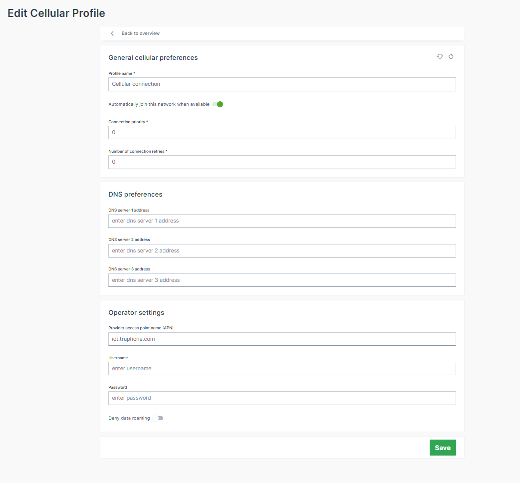
Note
Adjust the Cellular interface carefully considering the SIM traffic consumption.
- Profile name: Add a new profile name.
- Automatically join this network when available: When enabled, it activates this interface profile and takes care that the CANlink® mobile 10000 will try to connect to a network automatically.
- Connection priority: The higher the number (starting at
0), the higher the priority this interface profile is given over other profiles on the same interface for establishing a connection, see Profiles. - Number of connection retries: Specifies how many times a connection attempt should be made using this interface profile before the next interface profile is used according to the connection priority.
- Deny data roaming: To deny the data roaming is not recommended for international deployments as it would block any usage of the device in countries foreign to the SIM card.
- Via the Advanced Settings, you can adapt the SIM settings to enable the PIN (default: disabled).
Virtual Ethernet-WiFi Bridging Network Profile
With the Bridging interface active, Ethernet and WiFi are virtually linked and connected devices, whether via Ethernet or WiFi, are part of the same network and can communicate with each other.
A single IP address is configured with the Virtual Ethernet-WiFi Bridging Network Profile, which is used to set up the network other clients can connect to. The CANlink® mobile 10000 acts as the gateway to allow clients on both interface to communicate.
Thereby, you can avoid connecting Ethernet cables for diagnostics as access to Ethernet clients is possible via the WiFi interface.
Note
If the CANlink® mobile 10000 acts as a DHCP server, it must not be connected to a network with another DHCP Server to avoid network issues.
Exemplary application for the Bridging interface could be as follows:
Laptop -> WiFi Hotspot (CANlink® mobile 10000) -> Ethernet LAN (CANlink® mobile 10000) -> various devices in the network.
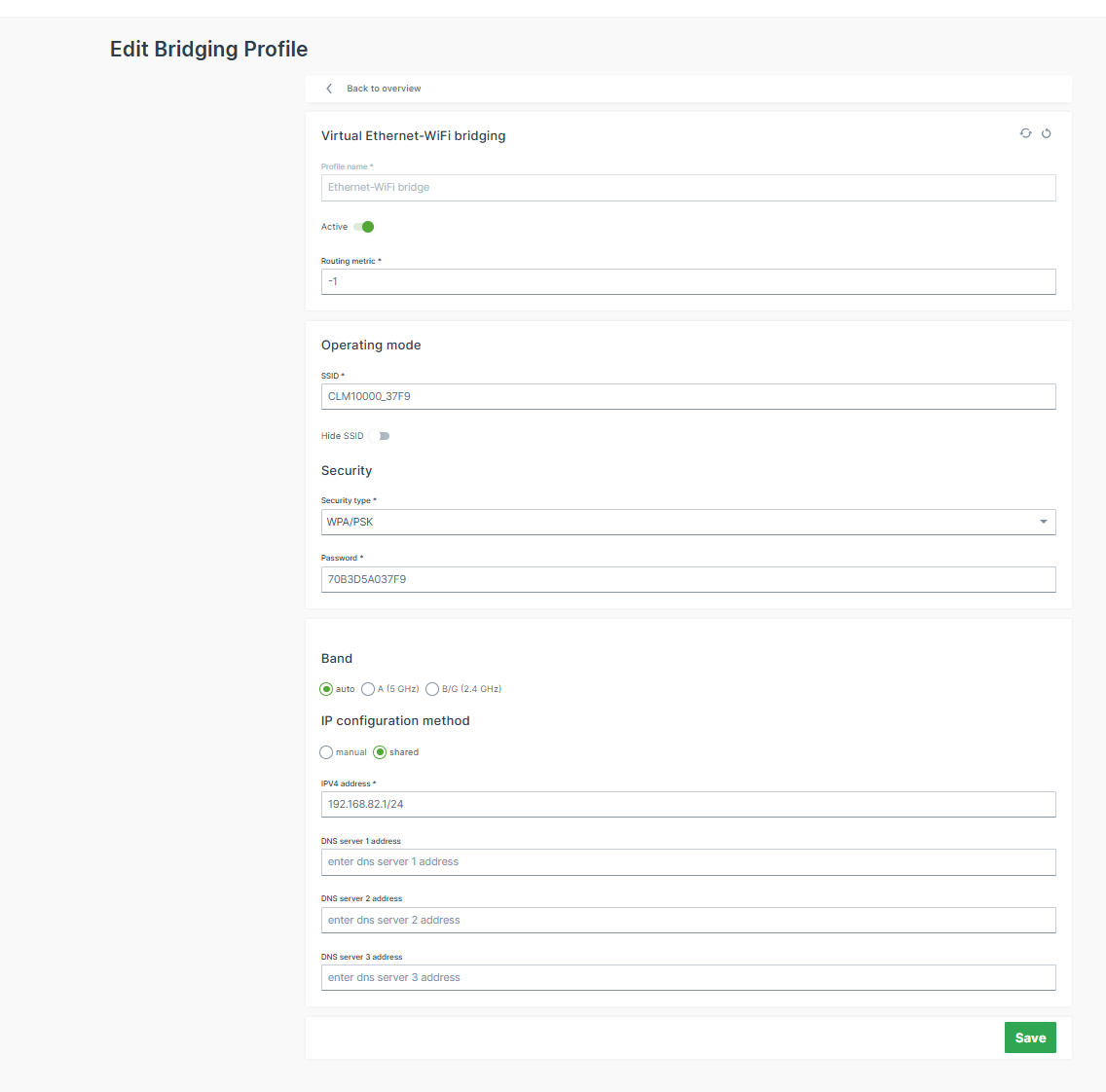
In the Virtual Ethernet-WiFi bridging you can configure the network profile for the Bridging interface (note that you configure only 1 profile, not multiple as in the other network connections):
- SSID: Name of the WiFi Access Point.
- IP configuration method:
- shared (default): The CANlink® mobile 10000 acts as the DHCP Server of the network assigning IP addresses to connected clients.
- The configured IP address (default:
192.168.82.1) is assigned to the CANlink® mobile 10000 and is used to set up the network. - The IP address and netmask must be entered according to the CIDR notation.
Example: If you want to set the IP address of the CANlink® mobile 10000 to192.168.82.1and the netmask to255.255.255.0, then you must enter192.168.82.1/24into the IP address field.
The CANlink® mobile 10000 also acts as a DHCP server in this "shared" method. That means, if you configured192.168.82.1/24via the IP address, the CANlink® mobile 10000 will assign IP addresses from192.168.82.2to192.168.82.254. - The range of the DHCP pool used for dynamic IP address assignment can be specified. This allows a range to be reserved for clients' static IP addresses.
- Allow internet access for connected clients: With this enabled the CANlink® mobile 10000 shares the Internet access with the network.
- The configured IP address (default:
- manual: The configured IP address will be used. But the CANlink® mobile 10000 does not act as a DHCP server.
- The DNS server settings are configurable.
- shared (default): The CANlink® mobile 10000 acts as the DHCP Server of the network assigning IP addresses to connected clients.
Note
The IP settings may be differently configured for the different profiles. Therefore, make sure to properly configure the profiles, when switching interfaces (see Operation Mode); otherwise you may lose the connectivity to the configuration web UI.
Ethernet Network Profile
The Ethernet Network Profile can be used to communicate with other devices accessible via Ethernet or even go online without the Cellular modem by making use of an already existing modem on the machine. Possible use cases are:
- Data transfer between devices.
- Access Internet via Ethernet connection when the Cellular connection is insufficient.
- Establish a DataPlatform connection over an Internet router connected via Ethernet.
The CANlink® mobile 10000 is always delivered with a unique Ethernet MAC address (accessible via the type label) and can be identified in your LAN network via the Ethernet MAC address.
Thereby, the IP address assigned by the DHCP server can be found out in case the CANlink® mobile 10000 is configured to act as a DHCP client on the Ethernet network, see profile settings below.
Note
When the Bridging interface option is active, the Ethernet interface is automatically enabled, see Operation Mode. The individual Ethernet interface profiles become invalid.
Add new Ethernet Settings - Connection Profile
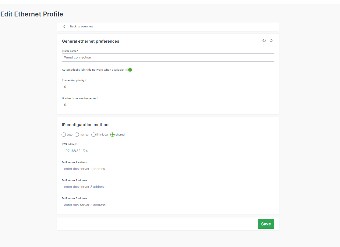
- Profile name: Add a new profile name.
- Automatically join this network when available: When enabled, it activates this interface profile and takes care that the CANlink® mobile 10000 will try to connect to a network automatically.
- Connection priority: The higher the number (starting at
0), the higher the priority this interface profile is given over other profiles on the same interface for establishing a connection, see Profiles. - Number of connection retries: Specifies how many times a connection attempt should be made using this interface profile before the next interface profile is used according to the connection priority.
-
IP configuration method:
- auto: CANlink® mobile 10000 acts as a DHCP client and gets IP address assigned by the DHCP Server (e.g., router or gateway on the machine).
- The DNS server settings are configurable.
- manual: The configured IP address will be used.
- Choose this option if a static IP address should be used.
- This can be used if there is no DHCP server on the network to assign an IP address or the CANlink® mobile 10000 must obtain a static IP address instead of having one dynamically assigned by the DHCP server. Please verify that the configured IP address is within the router's subnet.
- The DNS server settings are configurable.
- link-local: Link-local addressing (APIPA – Automatic Private IP Addressing) assigns an IPv4 address in the range
169.254.0.0/16when no DHCP server is available. This allows basic communication with devices in the same local network segment without requiring a DHCP server. - shared (default): The CANlink® mobile 10000 acts as the DHCP Server of the network assigning IP addresses to connected clients.
- The configured IP address (default:
192.168.82.1) is assigned to the CANlink® mobile 10000 and is used to set up the network. - The IP address and netmask must be entered according to the CIDR notation.
Example: If you want to set the IP address of the CANlink® mobile 10000 to192.168.82.1and the netmask to255.255.255.0, then you must enter192.168.82.1/24into the IP address field.
The CANlink® mobile 10000 also acts as a DHCP server in this "shared" method. That means, if you configured192.168.82.1/24via the IP address, the CANlink® mobile 10000 will assign IP addresses from192.168.82.2to192.168.82.254. - The range of the DHCP pool used for dynamic IP address assignment can be specified. This allows a range to be reserved for clients' static IP addresses.
- Allow internet access for connected clients: With this enabled the CANlink® mobile 10000 shares the Internet access with the network.
- The configured IP address (default:
- auto: CANlink® mobile 10000 acts as a DHCP client and gets IP address assigned by the DHCP Server (e.g., router or gateway on the machine).
Note
If the CANlink® mobile 10000 acts as a DHCP server, it must not be connected to a network with another DHCP Server to avoid network issues.
Ethernet Access Point with Internet Access
You can share the Internet access from the cellular or external modem via Ethernet. Proceed as follows:
- The CANlink® mobile 10000 is set up to go online via WiFi (see WiFi Network Profile) and/or via Cellular (see Cellular Network Profile).
- Configure the Ethernet interface as the interface that forwards/shares the Internet connection:
- Set the IP configuration method of the Ethernet to
sharedand configure it; thereby the CANlink® mobile 10000 also acts as the DHCP server on the Ethernet network. - Turn on the setting Allow internet access for connected clients.
- Connect the CANlink® mobile 10000 to an Ethernet network to become the Internet router with a DHCP server.
- Set the IP configuration method of the Ethernet to
- The CANlink® mobile 10000 uses the IP address configured by the user and assigns IP addresses to connected devices.
Now, every device connected to the shared Ethernet interface of the CANlink® mobile 10000 can access the Internet.
Note
For the shared option, you can choose one or both interfaces, WiFi and Ethernet, to share the Internet connection. But, the interface used by the CANlink® mobile 10000 to go online cannot share Internet access at the same time.
If, for example, the CANlink® mobile 10000 goes online over a WiFi network, then the WiFi interface of the CANlink® mobile 10000 cannot be used to share the Internet connection. However, sharing via Ethernet would work here.
If the CANlink® mobile 10000 goes online via the cellular modem, sharing Internet via WiFi and Ethernet is possible.
WiFi Network Profile
The WiFi Network Profile can be used to communicate with other devices accessible via WiFi or even go online without the Cellular modem by making use of an already existing modem on the machine. Possible use cases are:
- Data transfer between devices.
- Access Internet via WiFi connection when the Cellular connection is insufficient.
- Establish a DataPlatform connection over an Internet router connected via WiFi.
Note
When the Bridging interface option is active, the WiFi interface is automatically enabled, see Operation Mode. The individual WiFi interface profiles become invalid.
Add new WiFi Settings - Connection Profile
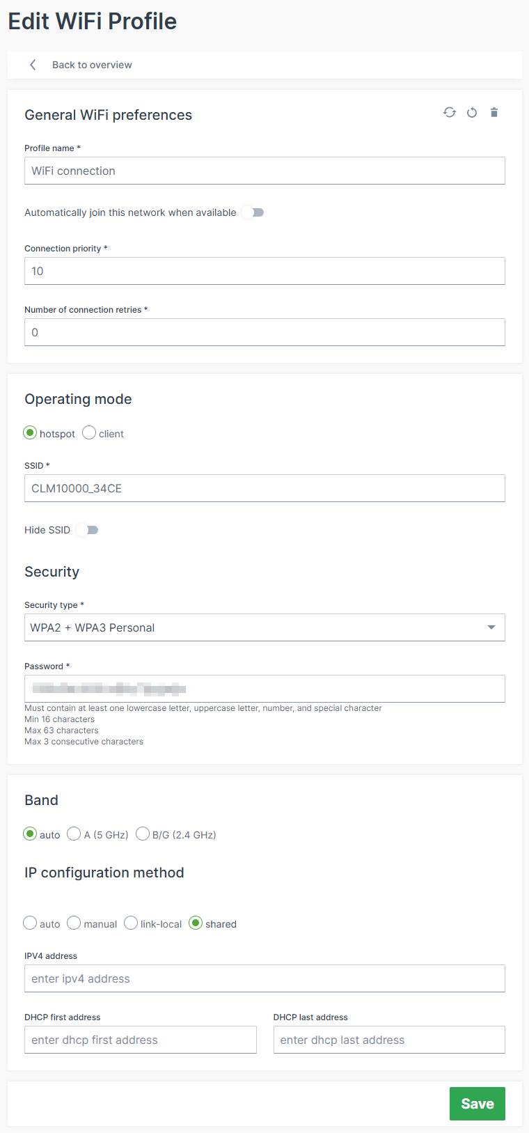
- Profile name: Add a new profile name.
- Automatically join this network when available: When enabled, it activates this interface profile and takes care that the CANlink® mobile 10000 will try to connect to a network automatically.
- Connection priority: The higher the number (starting at
0), the higher the priority this interface profile is given over other profiles on the same interface for establishing a connection, see Profiles. - Number of connection retries: Specifies how many times a connection attempt should be made using this interface profile before the next interface profile is used according to the connection priority.
- Operating mode: The CANlink® mobile 10000 can be used as a client or hotspot/AccessPoint; the hotspot mode allows clients to connect to the CANlink® mobile 10000 using the SSID and the password (e.g. WPA2/PSK). Consider also the IP configuration method Shared below.
- hotspot
- client
- SSID: Name of the WiFi Access Point.
- BSSID: not required; is the MAC address of the WiFi.
- Security: Choose the authentication method.
- IP configuration method: Choose the client communication type:
- auto: CANlink® mobile 10000 acts as a DHCP client and gets IP address assigned by the DHCP Server (e.g., router or gateway on the machine).
- The DNS server settings are configurable.
- manual: The configured IP address will be used.
- Choose this option if a static IP address should be used.
- This can be used if there is no DHCP server on the network to assign an IP address or the CANlink® mobile 10000 must obtain a static IP address instead of having one dynamically assigned by the DHCP server. Please verify that the configured IP address is within the router's subnet.
- The DNS server settings are configurable.
- shared (default): The CANlink® mobile 10000 acts as the DHCP Server of the network assigning IP addresses to connected clients.
- The configured IP address (default:
192.168.83.1) is assigned to the CANlink® mobile 10000 and is used to set up the network. - The IP address and netmask must be entered according to the CIDR notation.
Example: If you want to set the IP address of the CANlink® mobile 10000 to192.168.83.1and the netmask to255.255.255.0, then you must enter192.168.83.1/24into the IP address field.
The CANlink® mobile 10000 also acts as a DHCP server in this "shared" method. That means, if you configured192.168.83.1/24via the IP address, the CANlink® mobile 10000 will assign IP addresses from192.168.83.2to192.168.83.254. - The range of the DHCP pool used for dynamic IP address assignment can be specified. This allows a range to be reserved for clients' static IP addresses.
- Allow internet access for connected clients: With this enabled the CANlink® mobile 10000 shares the Internet access with the network.
- The configured IP address (default:
- auto: CANlink® mobile 10000 acts as a DHCP client and gets IP address assigned by the DHCP Server (e.g., router or gateway on the machine).
To connect the CANlink® mobile 10000 to a WiFi access point with DHCP server as a DHCP client, configure the following settings:
- Set Operating mode to client.
- Set SSID of the access point the CANlink® mobile 10000 should connect to.
- Choose for Security between WPA2 + WPA3 Personal or WPA3 Personal only (SAE) as the authentication method of the access point.
- Set the credentials based on the selected authentication method valid for the access point.
- Configure the IP configuration method of the CANlink® mobile 10000 to auto to act as a DHCP client on the WiFi network.
- The CANlink® mobile 10000 can now establish a connection to the configured access point and successfully authenticates; gets its IP address assigned from the DHCP server running on the access point;
- If the access point offers Internet access the CANlink® mobile 10000 can use this as access point to the Internet as well.
WiFi Access Point with Internet Access
You can share the Internet access from the cellular or external modem via WiFi. Proceed as follows:
- The CANlink® mobile 10000 is set up to go online via the Ethernet (see Ethernet Network Profile) and/or via Cellular (see Cellular Network Profile).
- Configure the WiFi interface to act as a hotspot/access point that forwards/shares the Internet connection.
- Set Operating mode to hotspot.
- Set up SSID Security for the hotspot.
- Set the IP configuration method of the WiFi to
sharedand configure it; thereby the CANlink® mobile 10000 also acts as the DHCP server on the WiFi network. - Turn on the setting Allow internet access for connected clients.
- The CANlink® mobile 10000 uses the IP address configured by the user and assigns IP addresses to connected devices.
You can now find and connect to the WiFi hotspot of the CANlink® mobile 10000 via a third-party device (e.g. a laptop) and can access the Internet.
Note
For the shared option, you can choose one or both interfaces, WiFi and Ethernet, to share the Internet connection. But, the interface used by the CANlink® mobile 10000 to go online cannot share Internet access at the same time.
If, for example, the CANlink® mobile 10000 goes online over a WiFi network, then the WiFi interface of the CANlink® mobile 10000 cannot be used to share the Internet connection. However, sharing via Ethernet would work here.
If the CANlink® mobile 10000 goes online via the cellular modem, sharing Internet via WiFi and Ethernet is possible.
Fallback strategies
Warning
The default priority of the different Network interfaces is as follows: Ethernet > WiFi > Cellular
Fallback to WiFi to get Internet access
- Configure the CANlink® mobile 10000 to be able to access the Internet via Ethernet, WiFi and the internal cellular modem - Make sure all configured network connections are reachable.
- To define the order the interfaces are used to connect to the Internet, the Routing Metric is used which is configured for each interface profile in the Advanced Settings.
- The profile with an active connection and the lowest routing metric will be used to establish the Internet connection. In this example, the Ethernet profiles are configured to have the lowest Routing Metric and therefore the CANlink® mobile 10000 establishes the Internet connection via the Ethernet interface.
- When The Ethernet connection of the CANlink® mobile 10000 drops for some reason and the WiFi interface has the next higher Routing Metric the CANlink mobile routes the Internet traffic automatically to the WiFi interface.
- The CANlink® mobile 10000 uses the WiFi connection for Internet connection until the Ethernet interface is available for the Internet connection again.
Note
You may use the Connection Priority to define a prioritized order of the interface profiles for one interface (e.g. the Ethernet interface) to establish a connection.
In case one Ethernet profile is not valid to establish a connection to the network the next Ethernet profile will be used and so on. But there might not be Internet connectivity on the network or it might not be used.
Note
If the Ethernet connection drops and the WiFi interface has the next higher Routing Metric, the CANlink® mobile 10000 routes the Internet traffic automatically to the WiFi interface.
Fallback to the internal cellular modem to get Internet access
- Configure the CANlink® mobile 10000 to be able to access the Internet via Ethernet, WiFi and the internal cellular modem. - Make sure all configured network connections are reachable.
- The CANlink® mobile 10000 establishes an Internet connection via the Ethernet interface based on the lowest Routing Metric for the Ethernet interface profile.
- Set up the Cellular interface profile to have the next higher Routing Metric.
- When The Ethernet and WiFi connection of the CANlink® mobile 10000 drop for some reason, the CANlink® mobile 10000 automatically switches to use the internal cellular modem for the Internet connection - provided that the Cellular interface profile used to establish the connection has the next higher Routing Metric than for the Ethernet connection that just dropped.
Remote Machine Tunnel
In the Remote Machine Tunnel menu you can configure whether this service should be enabled and allow remote connections to the machine.
Updates
Under Updates, you find the menus
- Firmware
- Configuration
Firmware
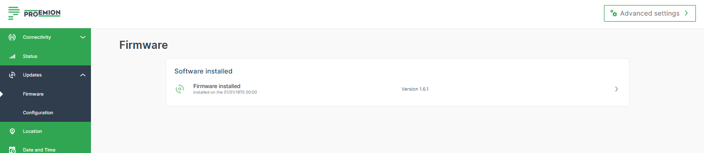
In the Firmware menu you can update the application firmware and view the history of the currently installed firmware.
You find the information about the installed firmware version also at the top and in the bottom left corner of the sidebar.
To upgrade the firmware, proceed as follows:
- Open the Updates > Firmware menu.
- Click in the field of the latest firmware to open the Upgrade firmware page.
- You can upload the firmware file of the format
.swu. - Click Install to upload the file and start the upgrade process. A message about the pending process will be displayed.
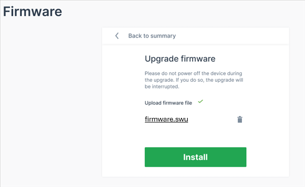
✓ When the firmware upgrade was successful, the configuration web UI will be reloaded and success message will be displayed. The installed firmware will be then listed in the Firmware menu.
Configuration
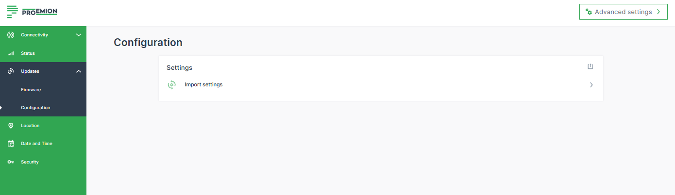
In the Configuration menu you can either update (import) the configuration or export the configuration settings.
All the configuration made via the Web UI are stored in a .clm file.
Note
The configuration file does not include the CODESYS application. A connection to this could be done via the Remote Machine Tunnel connection (connecting to the device as if it is on your network; device connected to the DataPortal via the mobile network).
Export Settings
To export the configuration settings, on the upper-right, click the export icon ![]() .
.
This configuration file can then be uploaded to the DataPortal via Settings > Configuration Bundle > +Add new configuration: Upload CLM10K files
This way, you could use configuration-over-the-air (COTA) for applying the configuration file to the fleet.
Import Settings
You can upload a configuration file to apply it on one device.
To upload a configuration file, proceed as follows:
- Open the Updates > Configuration menu.
- Click in the field Import settings.
- You can upload the configuration file of the format
.clm. - Click Install to upload the file and start the upgrade process.
✓ When the configuration upgrade was successful, the success message will be shown.
Location
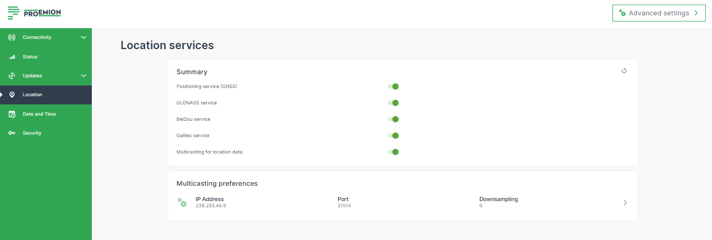
In the Location menu you can generally enable/disable the Positioning service (GNSS).
If enabled, the GPS service will be enabled by default.
In addition, you can enable other location services, e.g. Galileo service.
Date and Time
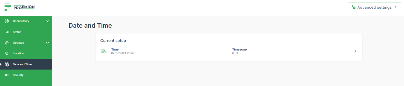
In the Date and Time settings, you can manually set the time together with the time zone or receive them automatically.
By default, the CANlink® mobile 10000 uses the Network Time Protocol (NTP) to automatically synchronize the system time via the Internet.
For this purpose, the device opens UDP port 123, which is required for communication with NTP servers.
Ensure that UDP port 123 is open in your network environment to allow proper time synchronization.
If needed, NTP-based time synchronization can be disabled under Advanced Settings > Date and Time.
The option to manually adjust the time is provided for use cases where the machine is located in an area where the time and time zone cannot be reliably retrieved automatically.
Note
The change of Date and Time settings is applied system-wide in the CANlink® mobile 10000. It might need an Internet connection for the changes to apply.
Power Management
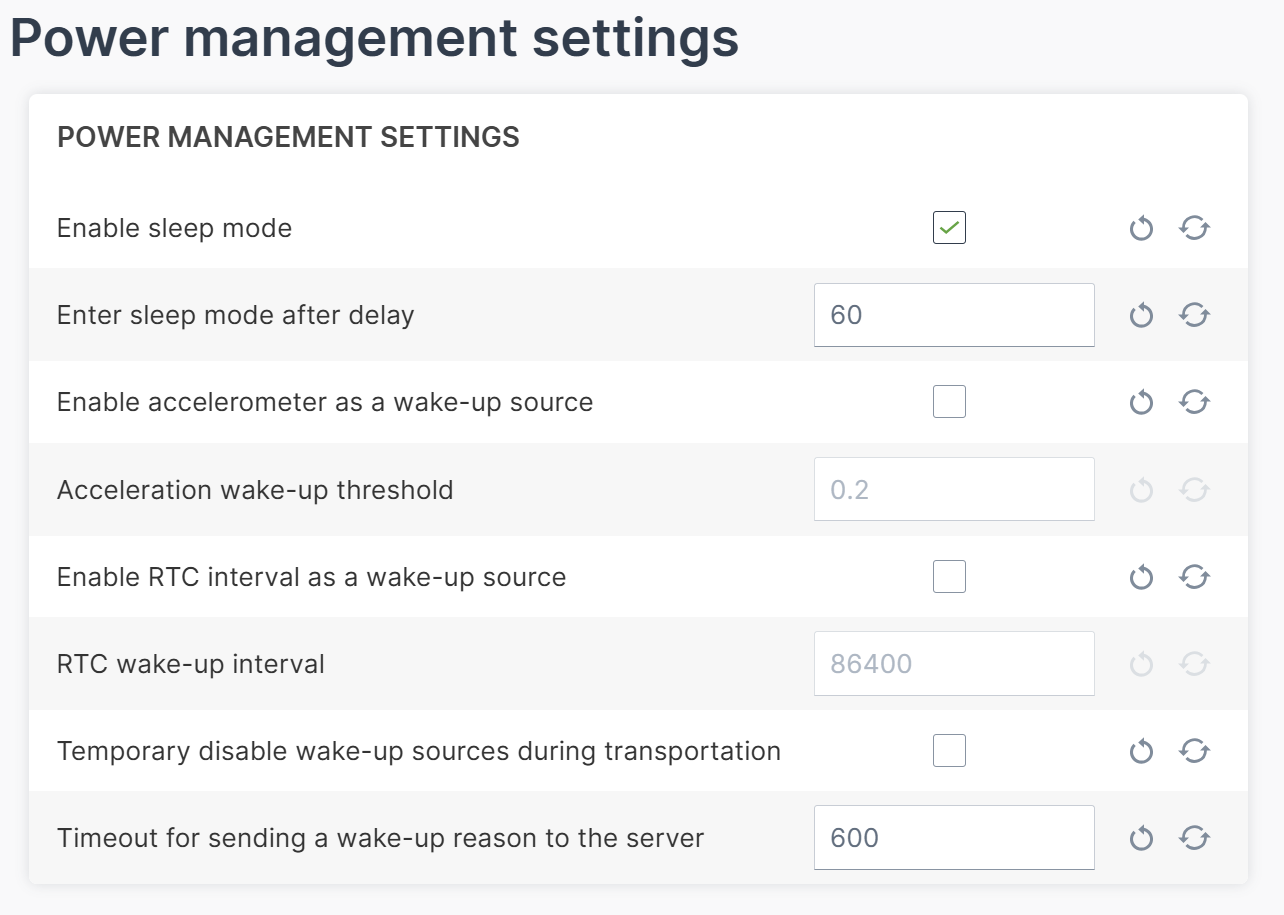
In the Power Management menu, you can activate the option Enable sleep mode and configure its settings. For detailed information refer to the chapter Power management.
Security
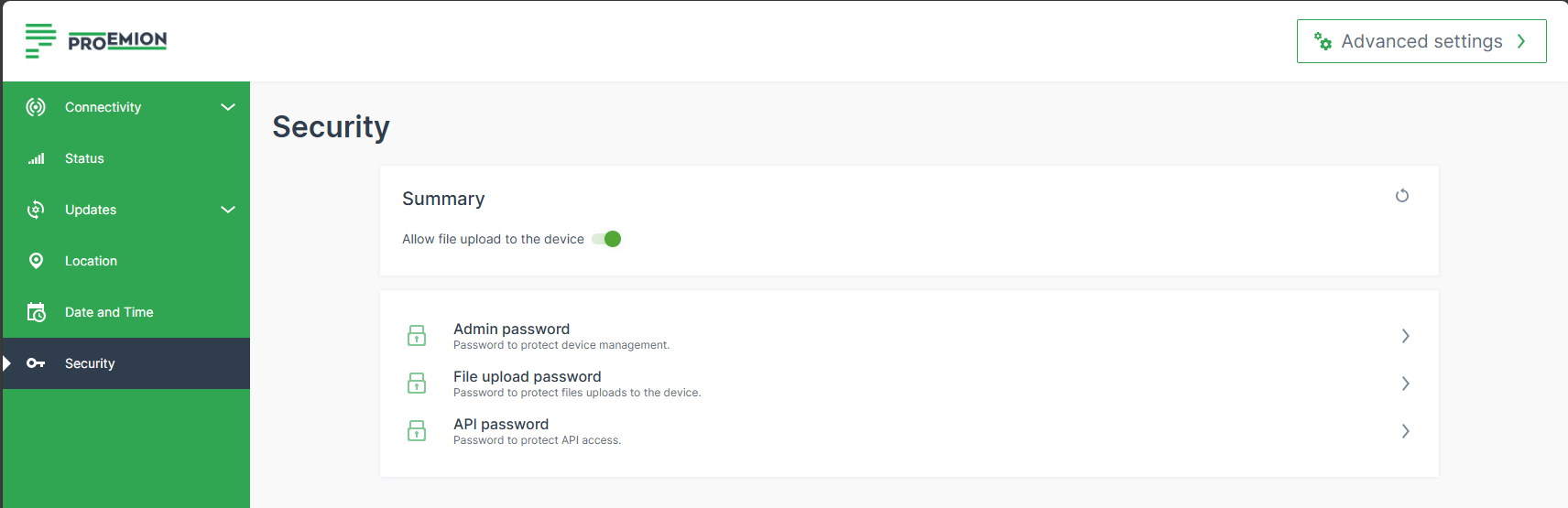
In the Security settings, you can change the password for the admin, upload and api users.
File upload can be deactivated by disabling the Allow file upload to the device option. Once disabled, files can no longer be pushed to the CANlink® mobile 10000 via the device JSON API endpoint and consequently not to the DataPlatform either.
| User | Configuration Web User Interface Access | Device’s JSON API Access |
|---|---|---|
| admin | Yes. | Yes. |
| api | No. | Yes, limited scope. |
| upload | No. | Yes, only file upload endpoint. |
Diagnostics
For troubleshooting and support, you can download a system log file directly from the CANlink® mobile 10000 configuration web UI.
Prerequisites
To downloading the system log file, ensure that you are either:
- Connected locally to the CANlink® mobile 10000 and logged in to the configuration web UI, or
- Connected remotely to the CANlink® mobile 10000 through the Remote Machine Tunnel.
To download the system logs, open the following URL in your browser:
https://< ip-address-of-the-device >/logs
Example:
https://192.168.82.1/logs
Note
Generating the log archive runs in the background and can take up to 30 seconds. No progress indicator is displayed. The download starts automatically when the archive is ready.
The system log file is downloaded as a compressed archive named logs-latest.tar.gz.
The archive contains the following information:
- Timestamp indicating when the archive was created
- Device configuration
- CODESYS logs
- For each boot partition:
- System logs and messages
- Proemion application information
- Filesystem and memory usage information
If requested, share the archive with Service and Support to assist with troubleshooting.
Advanced Settings
In the Advanced Settings, you may adapt the settings described above and configure more details, e.g. routing metric:
You can define the Routing metric used to make a routing decision. for each interface.
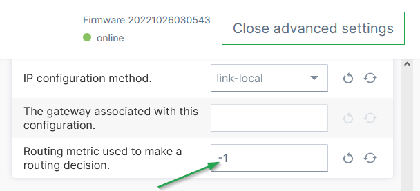
This option can be used to define/reorder the default routing, i.e. the preferred network the CANlink® mobile 10000 will choose for connecting to the DataPlatform.
The default value -1 means that the metric is chosen automatically.
Note
Make sure that other settings are adjusted accordingly in order to change the priority, e.g. en-/disabling the interface or the Autoconnect priority. etc.
Example of adjusting the routing metric:
- Enter an arbitrary, positive number for the routing metric of the interfaces. The lower value gives preference, e.g.:
- Ethernet routing metric: 100
- WiFi routing metric: 200
- Cellular routing metric: 300
- If you want the device to prefer the Cellular interface, change only the Cellular routing metric for instance to
10; the other interface remain as is, i.e Ethernet 100, WiFi 200.
Status
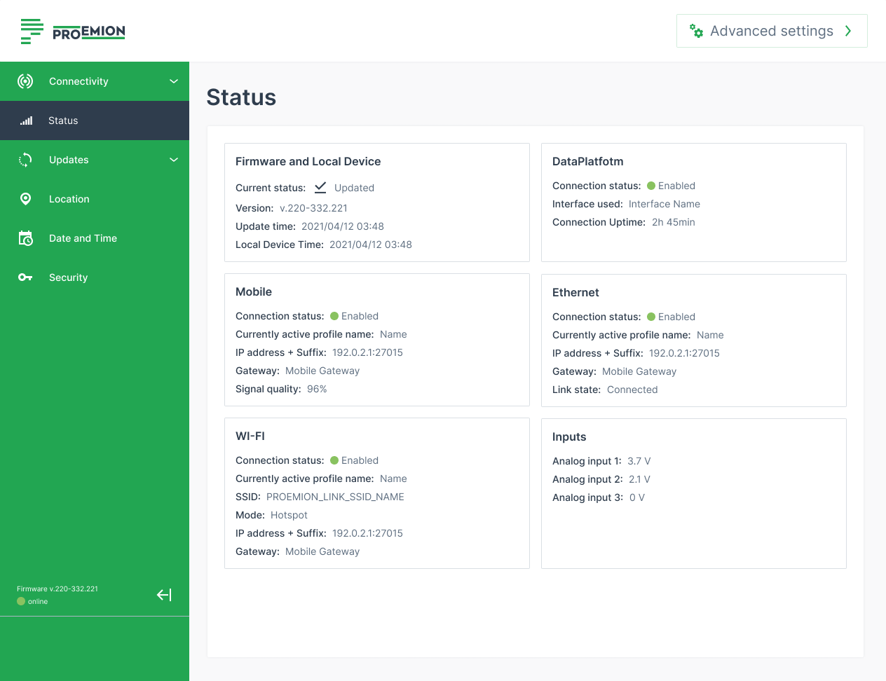
The Status page in the configuration web UI shows the device's status information about various interfaces and connections.
These can be used e.g. to check which of the configured connections are currently active and with which characteristics:
-
Firmware and Local Device: Check the current firmware version.
-
DataPlatform: Check which network interface is enabled to connect to the DataPlatform.
-
Mobile, Ethernet, Wi-Fi: Check the statically defined or dynamically assigned IP addresses of the active interfaces; check the signal strength of the cellular connection, etc. For more information, read Network.
-
Inputs: Check the analog inputs that measure the applied voltage.
API
JSON REST API
The JSON REST API enables external applications and services to communicate with the CANlink® mobile 10000.
Using the API, device-related information and functionality can be accessed remotely via HTTPS-based endpoints using JSON formatted request and response payloads.
All JSON REST API endpoints except File Upload require HTTPS transfer.
File Upload
This section focuses on the file upload from the CANlink® mobile 10000 device to the DataPlatform.
For uploading files to the CANlink® mobile 10000, you can use the REST API endpoint, see Transfers.
The CANlink® mobile 10000 API allows to upload files from the machine to the DataPlatform, thus DataPortal via the upload endpoint.
This endpoint allows the upload of any file format including special file extensions. The files will only be stored and made available for download on the DataPlatform. There will be no processing of the files except for .clf file types, these are reserved for internal use.
In the DataPortal, the files are then to be found in Settings > Communication Unit management > File Transfers, see File Transfer.
Note
Consider that you need Machine:Admin permissions to view the Transfers menu on DataPortal.
Restrictions
The file size is limited for the file upload to 50 MB from the CANlink® mobile 10000 device to the DataPlatform.
-
Filename (before the dot):
- Can contain letters, numbers, underscores (
_), and hyphens (-) - No spaces or special characters allowed
- Must be 1 to 256 characters long
- Can contain letters, numbers, underscores (
-
File extension (after the dot):
- Must be 1 to 10 characters long
- Can include only letters and numbers
- No special characters allowed
If the configuration is set to prevent automatic file upload to the DataPlatform, the files remain in the CANlink® mobile 10000's non-volatile memory until the automatic upload has been enabled again.
Request
URL/Path
Use the following path to upload the files from the machine:
http(s)://{{ address }}/upload
Example:
https://192.168.82.1/upload
It is highly recommended to use HTTPS whenever possible.
Note
To enable the http:// transfer, the HTTP option must be explicitly set in the configuration.
See also Security in the chapter Configuration Web User Interface.
Method
Use POST as the HTTP method.
Request Header
| Key | Value | Note |
|---|---|---|
| Authentication | Basic Auth | Basic Authentication with username and password is used as the authorization type. The username is upload and isn't changeable. There is no default password for the uploads; before using the feature, you must explicitly set a password (or alternatively, disable password protection) in the configuration web UI. The passwords are write-only and cannot be read back. See also Security. |
| Content-Type | form-data | - |
Request Body
| Key | Value | Note |
|---|---|---|
| file | Any binary file | Read about the Restrictions. |
Response
There are the following HTTP Status Codes:
| Status | Note |
|---|---|
| 200 | OK, file transfer to the DataPlatform succeeded. |
| 400 | Bad request (missing required file form field, missing form field value (file name), not a POST. |
| 401 | Authentication failure, i.e. wrong username (must be upload) or wrong password. |
| 403 | Transfer forbidden, file uploads to the unit have been disabled by the user in the device configuration. |
| 413 | Payload too large, currently the size of the upload is limited to 1 MB per file. |
| 500 | Unexpected internal error in the application, review the logs. |
Access uploaded Files on DataPlatform
You can obtain the uploaded files as follows:
-
In the DataPortal go to Settings > Communication Unit management > File Transfers and click Save to download the file. For more information, read File Transfer in the DataPortal User Manual.
-
For the download of the files from the DataPlatform, read Transfers in the REST API.
Firmware Update
The CANlink® mobile 10000 API allows to update the firmware via the firmware endpoint.
This endpoint allows the upload of a firmware update in the .swu file format.
Note
Consider that the Configuration Web User Interface also allows the upload of firmware files.
Request
URL/Path
Use the following path to upload the files from the machine:
https://{{ address }}/firmware
Example:
https://192.168.82.1/firmware
Method
Use POST as the HTTP method.
Request Header
| Key | Value | Note |
|---|---|---|
| Authentication | Basic Auth | Basic Authentication with username and password is used as the authorization type. The username is admin and isn't changeable. The default password is the Ethernet MAC address in capital letters without colons. You can change the password in the configuration web UI (note that password protection cannot be disabled). The passwords are write-only and cannot be read back. See also [Security](configuration_web_user_interface.md#security |
| Content-Type | form-data | - |
Body
| Key | Value | Note |
|---|---|---|
| file | .swu binary file |
- |
Response
There are the following HTTP Status Codes:
| Status | Note |
|---|---|
| 200 | OK, firmware image transfer succeeded |
| 400 | Bad request (missing required file form field, missing form field value (file name), not a POST. |
| 401 | Authentication failure, i.e. wrong username (must be admin) or wrong password. |
| 500 | Unexpected internal error in the application, review the logs. |
After receiving the firmware image the device will start the firmware update procedure, a response code of 200/HTTP OK only means that the image has been accepted for further processing, it does not indicate a successful update.
In the Configuration Web User Interface, the successfully updated firmware will be displayed as new entry in the Updates > Firmware menu.
Configuration Update
The CANlink® mobile 10000 API allows to update the configuration via the config endpoint.
This endpoint allows the upload of a previously exported configuration in the .clm file format.
Consider that the Configuration Web User Interface also allows the upload of configuration files.
Request
URL/Path
Use the following path to upload the files from the machine:
https://{{ address }}/config
Example:
https://192.168.82.1/config
Method
Use POST as the HTTP method.
Request Header
| Key | Value | Note |
|---|---|---|
| Authentication | Basic Auth | Basic Authentication with username and password is used as the authorization type The username is admin and isn't changeable. The default password is the Ethernet MAC address in capital letters without colons. You can change the password in the configuration web UI (note that password protection cannot be disabled). The passwords are write-only and cannot be read back. See also Security. |
| Content-Type | form-data | - |
Body
| Key | Value | Note |
|---|---|---|
| file | .clm binary file |
- |
Response
There are the following HTTP Status Codes:
| Status | Note |
|---|---|
| 200 | OK, file transfer transfer succeeded |
| 400 | Bad request (missing required file form field, missing form field value (file name), not a POST. |
| 401 | Authentication failure, i.e. wrong username (must be admin) or wrong password. |
| 500 | Unexpected internal error in the application, review the logs. |
After receiving a configuration file the device will try to apply provided settings. The operation is atomic, meaning that either all settings can be applied successfully or nothing will be applied at all in case one or more settings fail. A response code of 200/HTTP OK only means that the config file has been accepted for further processing, it does not indicate if settings were applied.
In the Configuration Web User Interface, the successfully updated configuration will be displayed as new entry in the Updates > Configuration menu.
Protobuf API
The CANlink® mobile 10000 provides a Protocol Buffers based WebSocket API for communication with external applications and services.
Open Source Python Client
To simplify integration with the Protobuf API, the open source Python package clmprotoclient can be used.
The client simplifies interaction with the CANlink® mobile 10000 Protocol Buffers based WebSocket API by:
- Providing convenience methods for creating Protocol Buffer messages
- Handling WebSocket communication for sending and receiving messages
For contribution, further information, installation instructions, and source code, refer to:
Protobuf Wrapper
clmprotoclient depends on clmprotowrapper.
The wrapper package is automatically installed when installing clmprotoclient.
Power Management
To protect the device from damage and data loss, a correct wiring and configuration of the power management settings is mandatory. The main purpose of the power management settings is that the device has a safe shutdown before the supply voltage (terminal 30/31) is disconnected.
The Power Management settings allow you to configure how the device enters sleep mode and which events can wake it up again. Proper configuration helps reduce power consumption while ensuring that the device remains responsive to required wake-up triggers, such as movement or scheduled intervals. The Power Management settings can be accessed through the device Web UI under Advanced settings > Power management settings.
Note
Wake-up of the device is possible when at least one of following condition is fulfilled:
- The IO - Clamp 15 (Ignition) State is at level
high(> 6 V) - The Enable accelerometer as a wake-up source option in the power management settings is enabled and the configured threshold is exceeded
- The Enable RTC interval as a wake-up source option in the power management settings is enabled and the configured time is elapsed
The following subsections provide an overview of the individual power management functions.
For further information see also chapter Switching the Device On/Off.
Enable Sleep Mode
Enabling Sleep mode allows the device to automatically reduce power consumption when no activity is required. When this option is activated, all configured sleep and wake-up mechanisms become active.
To enable Sleep Mode, proceed as follows:
- Enable Sleep mode.
- Configure the desired optional sleep triggers described below.
Enter Sleep Mode After Delay
The Enter sleep mode after delay parameter defines how long the device continues normal operation before entering sleep mode if sleep mode has been enabled.
You can configure this setting as follows:
- Enable Sleep mode.
- Enter the desired delay time (in seconds).
- Apply the configuration.
Note
Ensure that the delay is long enough to allow pending tasks to finish before the device goes into sleep mode.
If Timeout for sending a wake-up reason to the server is also configured, the device only enters sleep mode once the wake-up reason has been successfully transmitted or the timeout for sending a wake-up reason to the server expired. See Timeout for Sending Wake-Up Reason for further details.
Accelerometer Wake-Up Source
The internal accelerometer can be used as a wake-up trigger when the device is in sleep mode. When enabled, the device wakes up as soon as the detected acceleration exceeds the configured threshold.
To configure accelerometer wake-up, proceed as follows:
- Enable Accelerometer as a wake-up source.
- Set the Acceleration wake-up threshold (in g). The minimum delta value for the threshold is 0.2 g, resulting in an actual wake-up force of 1.2 g on the sensor. The maximum value for the acceleration wake-up threshold is 16 g.
- Apply the configuration.
Note
Choosing a threshold that is too low may cause frequent unintended wake-ups due to vibration or handling.
RTC Interval Wake-Up Source
The RTC wake-up interval function allows the device to periodically wake up at a defined interval using its internal real-time clock.
To configure RTC interval wake-up, proceed as follows:
- Enable RTC interval as a wake-up source.
- Enter the RTC wake-up interval in seconds.
- Apply the configuration.
Note
Choose the interval based on the required update or reporting frequency. Very short intervals may reduce power-saving benefits.
Temporary Disable Wake-Up Sources During Transportation
This option allows you to temporarily disable all wake-up sources during transport, storage, or shipment. When enabled, neither accelerometer wake-up nor RTC interval wake-up will cause the device to start unintentionally.
To enable transport protection, proceed as follows:
- Enable Temporary disable wake-up sources during transportation.
- Apply the configuration.
Note
Once the device is deployed and requires regular operation, ensure that this option is disabled again to restore normal wake-up behavior.
Timeout for Sending Wake-Up Reason
The Timeout for sending a wake-up reason to the server parameter defines the maximum time the device will keep trying to transmit its wake-up reason before entering sleep mode. This prevents a failed or delayed transmission from blocking the device from entering sleep mode indefinitely.
When the CANlink® mobile 10000 wakes up or boots, it automatically attempts to send its wake-up reason to the DataPlatform. In some situations, for example due to missing network coverage or temporary connectivity issues, this upload may not be possible before the delay to enter sleep mode expired again. This setting allows to postpone entering sleep mode in case sending the wake-up reason is still pending.
If the wake-up reason is sent before the sleep mode delay expires, this setting does not have an impact and the CANlink® mobile 10000 enters sleep mode as configured. But if the wake-up reason has not been transmitted by the time the sleep mode delay expires, sleep mode is postponed until the transmission succeeds. The Timeout for sending a wake-up reason to the server defines the maximum postponement - once it expires, the device enters sleep mode regardless of whether the wake-up reason was transmitted.
To configure this setting, proceed as follows:
- Set the desired Timeout for sending a wake-up reason to the server (in seconds).
- Apply the configuration.
Note
A longer timeout increases the likelihood of a successful upload but may temporarily reduce power-saving efficiency, especially in areas with poor connectivity.
Interaction with Enter Sleep Mode After Delay
When both Enter Sleep Mode after delay and Timeout for sending a wake-up reason to the server are configured, the following rules apply:
- The device enters sleep mode at the earliest after Enter Sleep Mode after delay has expired - but only if the wake-up reason has already been transmitted by then.
- The device enters sleep mode at the latest after Timeout for sending a wake-up reason to the server has expired, regardless of whether the wake-up reason was transmitted.
- If Enter Sleep Mode after delay expires while the wake-up reason is still pending, the device continues trying to transmit. It enters sleep mode immediately once the wake-up reason is successfully sent.
| Scenario | Enter Sleep Mode |
|---|---|
| Wake-up reason sent before sleep mode delay expires | After sleep mode delay expires |
| Wake-up reason sent after sleep mode delay expires | Immediately after successful transmission |
| Wake-up reason cannot be sent | After the timeout for sending a wake-up reason to the server expires |
Safe Remote Update Guidelines
Safe Remote Updates Guideline
Introduction
Our firmware is subjected to an intensive testing process, including automated tests during development and dedicated testing for each final release candidate. This test suite is continuously expanded based on internal findings and field reports.
Despite these efforts, a residual risk of unexpected issues in specific scenarios remains.
To minimize this risk, we strongly recommend following the procedure outlined in this guideline when performing a remote firmware or configuration update campaign.
By adhering to these steps, you can significantly increase the safety and success rate of your update process.
Risk of Property Damage
It is strongly recommended not to remotely update all machines in a single step with a new configuration or firmware.
Remote Update Procedure
When planning a firmware or configuration roll-out, several steps should be considered to ensure the process is as safe and reliable as possible.
This guideline applies to each individual machine type or machine family. A machine family is defined by devices sharing the same configuration version, the same initial firmware, and — if applicable — the same SIM card settings.
Following these steps helps minimize the risk of update-related errors.
1. Initial Test on a Simulator or Sample Machine
Perform the first remote update on a simulator device whenever possible.
If a simulator is unavailable, use a single, easily accessible sample machine.
Verify that the update succeeds and that the device behaves as expected.
2. Update a Small Batch (Up to 10 Machines)
In the second step, extend the update to a maximum of 10 machines.
After completion, verify the success of the update on each machine individually.
3. Update a Partial Roll-out (Up to 15% of the Fleet)
If the second step is successful, proceed with a partial roll-out to a maximum of 15% of the fleet.
Conduct a success check after this roll-out as well.
4. Update the Remaining Fleet
Once all prior steps have been validated, roll out the update to the rest of the fleet.
Verifying Update Success
Between each roll-out step, perform sample checks to ensure that devices are operating as expected. Verification should include:
- Device startup and shutdown behavior in the machine environment
- Logged operational data
- File transfer to your ECU
- Execution of configured actions
- Any special or device-specific behaviors configured in your system
Key Changes in Firmware 3.1.0
This release introduces important security, configuration, and service changes.
CODESYS Runtime and EdgeGateway Service Configuration
To improve device security and minimize unnecessary service exposure, the following changes have been introduced:
- CODESYS Runtime and EdgeGateway are disabled by default. Enable services to restore functionality:
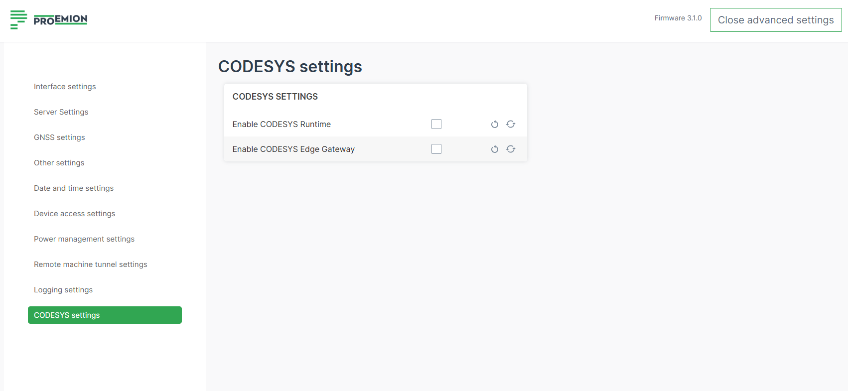
Note
Existing CODESYS applications will not run until services are manually re-enabled.
- This is a persistent configuration; future firmware updates will not reset this setting.
- Use COTA with
.clmsettings files for efficient updates. Verify all Wi-Fi profiles to ensure settings are correctly applied.
Note
Test changes first on a single device; Hotspot password changes may be necessary.
The device description has been updated from version 4.9.0.0 to 4.17.0.0..
You need to download and install the CODESYS Add-on - CODESYS Control for Linux ARM SL version 4.17.0.0 and update your applications. Right-click on the Device (CODESYS Control for Linux ARM SL) and select Update Device from the menu:
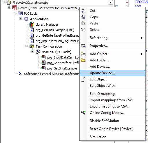
Password Policy Update
To further enhance device security, passwords for accessing the device will follow a revised and more robust password policy:
- Length: 8–63 characters.
- Must include: one uppercase, one lowercase, one number, one special character.
- A maximum of 3 identical consecutive characters is allowed.
Note
Wi-Fi Pre-Shared Key (PSK) for client mode is not affected by this change to maintain compatibility with certain legacy devices.
Wi-Fi Security and Operating Mode Changes
To align with modern security standards and ensure reliable wireless communication, several outdated or less secure Wi-Fi modes have been removed from the available configuration options.
- Removed insecure or deprecated modes:
- Open (unencrypted) networks
- OWE (Opportunistic Wireless Encryption)
- WPA2 + WPA3 Enterprise (combined mode)
- Wi-Fi ad-hoc mode is removed.
- Existing configurations using these modes will remain functional temporarily, but the corresponding settings will be marked as deprecated.
- Firmware enforcement:
- Deprecated Wi-Fi security modes rejected from firmware versions ≥ 2.0.0
- Ad-hoc mode rejected from firmware versions ≥ 3.0.0
- Future support for WPA2 + WPA3 Enterprise may be reintroduced on request with a defined setup.
SSH Service Behavior
To enhance device security and reduce potential attack surfaces, the SSH service is no longer active in the factory default configuration.
- SSH is disabled by default on newly produced devices.
- Users can manually enable the SSH service on demand when remote access is required.
- Activation requires uploading a public key via the JSON API SSH endpoint.
This change ensures that SSH access is only available to authorized users and initiated through a secure key-based authentication process.
Troubleshooting and Maintenance
This chapter contains information on solving problems and on maintenance.
Cleaning
Risk of property damage
Damage to the device due to water penetration
-
The device was tested against water jets according to IPxK5 of ISO 20653 standard. Different loads, e.g., with a pressure washer or a higher flow rate, do not correspond to the intended use.
-
Never clean the CANlink mobile device with a pressure washer or similar.
To avoid damage caused by liquid ingress, no high-pressure cleaners may be used for cleaning. In order to remove contamination, you should also avoid using jet water if possible. Instead, use a damp cleaning cloth with a solvent-free and acid-free cleaning liquid. Make sure the device is mounted as recommended to avoid liquid ingress, see Mounting Orientation.
Downloading System Logs
If you are experiencing issues with the CANlink® mobile 10000 or have been asked to provide diagnostic information for a support case, you can download the system log file via the configuration web UI. See Diagnostics.
Packaging and Transport
This chapter contains information on packing and transportation. Read also the notices in the Important Device Information.
Note
Risk of property damage. - Only store and transport the device in a temperature range of -40 °C ... +75 °C / -40 °F ... +167 °F.
Note
Risk of property damage.
Protection class IP6K7 is only ensured when all connectors are correctly fitted with protection caps.
- Close all connectors with protection caps.
Note
Environmental damage due to lithium-polymer battery.
According to the valid transport regulations for lithium batteries, devices containing such batteries, or their transport packaging must be specially labeled. Prior to shipping, please contact our support.
- Only ship the device in a packaging that is appropriately labeled on the outside.
Disposal
This chapter contains information on correct disposal.
Regulations in the European Union
Note
Observe local regulations for disposal of the device, the accessories and the packaging material.
 |
According to the Directive on Waste Electrical and Electronic Equipment (WEEE), the device must not be disposed of in household waste. The device contains a lithium-polymer battery which can contain toxic and polluting heavy metals. Take the device to a collection point for waste electrical and electronic equipment for correct disposal. |
Environmental damage due to lithium-polymer battery
According to the valid transport regulations for lithium batteries, devices containing such batteries, or their transport packaging must be specially labeled.
Prior to shipping, please contact our Service and Support.
- Only ship the device in a packaging that is appropriately labeled on the outside.
Annex
This chapter contains technical data and certificates.
Technical Drawings
Note
You can download the CAD files from our Download Center under: 03_Proemion Tools Software > 01_Software.
Dimensions of the CANlink® mobile 10000
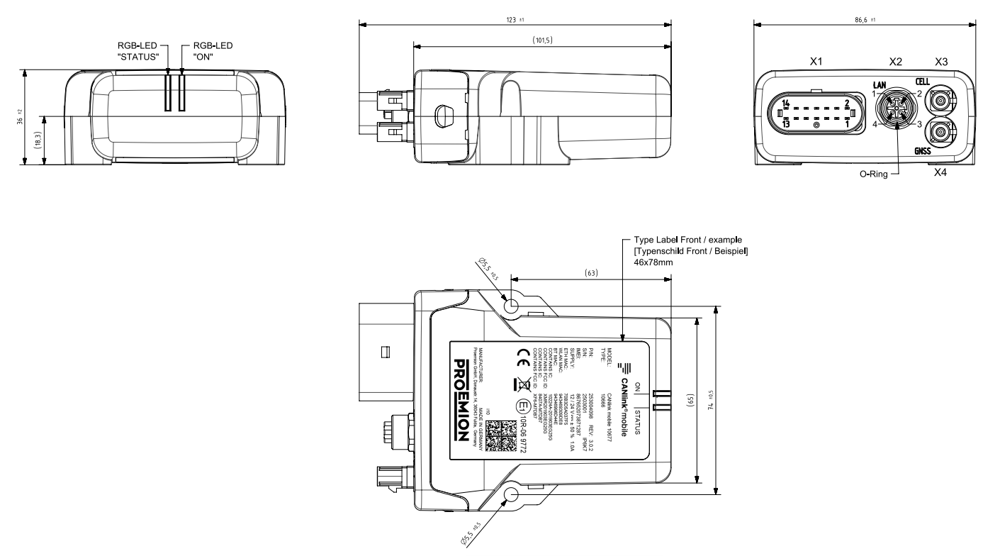
Technical Data
This chapter contains information on the technical data of the device.
Mechanical
| Parameter | Value |
|---|---|
| Dimensions width/height/depth [mm] | 86,6±1 / 123±1 / 36±2 |
| Color | Black |
| Protection class | IP6K7 The protection class is only ensured if all connectors of the device are plugged in or covered with suitable protection caps. |
| Operating temperature range for devices without battery | -40 °C ... +75 °C / -40 °F ... +167 °F The device or functions of the device like the radio interfaces will do a thermal protection Shutdown at the upper temperature limit, depending on device TYPE and device usage. |
| Operating battery temperature range for devices with battery | Battery discharging: -20°C...+60°C/-4°F...+140°F Battery charging: 0...+45°C / 32°F...+113°F Due to self-heating of the device, the battery temperature is approx. 15°C higher than the ambient temperature, depending on device TYPE and device usage. |
| Storage Temperature range | -40...+75°C / -40°F...+167°F |
| Altitude | The altitude during operation is limited to 2000m for CLM 10xxx devices. This requirement is part of the Electrical Safety Test for IEC 62368-1 |
| Weight | max. 220 g (type 10677) |
| Standard housing material | PA 66/6 - FR |
| Pressure equalizing membrane | Yes |
| Resistance of the housing material to chemicals | The housing material of the device was successfully tested against the following liquids in accordance with the standard EN ISO 175. - Exposure time: 24h - Temperature: 20°C, for Substances No. 5, 6, 7: 80°C - Rel. Humidity < 40% - Operating mode: Off 1. Gasoline 2. Diesel 3. Fast cleaner spray Tetrachlorethen 4. Ethanol 5. Chain adhesive lubricant 6. Hydraulic oil HLVP68 7. Hydraulic oil biologic BP Bio SE 46 8. Coca Cola 9. Cement CEM 1 DIN EN 197-1 „Quickmix" (Bauhaus) 10. Fertilizer NPK,Gardol Grünpflanzendünger 12-4-6 (Bauhaus) 11. Skin care Handsan Cream & Touch (dm) 12. Sunscreen "Sundance Sonnenmilch 20 mittel" (dm) 13. Cooler Antifreeze Type G12 14. Window cleaner concentrate 15. Suds Rivolta BWR 210, 10:1 |
Electrical
| Parameter | Value |
|---|---|
| Supply voltage range terminal 30 DC | Rated voltage 12V / 24V, Tolerance +-50%, range 6V to 36V |
| Battery voltage, battery operation | 3.7 V (internal) |
| Current consumption, with terminal 30 supply (24 V) (at 25°C) | < 290 mA (standard mode) < 1 mA (sleep mode) |
| Current consumption, battery operation (3.7 V) (at 25°C) | < 1000 mA (standard mode) < 0.5 mA (sleep mode) |
| Power consumption (at 25°C) | < 7 W |
| Controller | Arm Cortex M4 209 Mhz Arm Cortex A7 650 MHz |
| Memory NAND Flash /eMMC | 4 GB |
| Memory FRAM | 32 KB |
| Memory DDR3L-RAM | 512MB |
| LEDs | 2 LEDs, RGB (red/green/blue) |
| Keys | Push-button in main plug connector |
| Battery | Lithium-polymer, 3.7 V; 1.15 Ah; 4.225 Wh - Charge time: approx. 5 hours - Operating time: - approx. tbd h (standard mode) - approx. tbd days (24-hour cycle) - approx. tbd days (Sleep mode / Standby) |
| RTC with back-up capacitor | Back-up time: 48 h at 25 °C - Accuracy: ±2 s/day at 25 °C, -15 s/day at the lower and +2 s/day at upper temperature limit - Synchronization: GNSS/NTP/DataPlatform - Can be used as source for cyclic wakeup |
Interfaces
| Parameter | Value |
|---|---|
| CAN (number, ISO) | CAN1: ISO 11898-2 CAN2: ISO 11898-2 CAN3: ISO 11898-2 |
| Max. CAN baud rate | 1000 kbit/s, 5 Mbit/s with CAN-FD |
| Bluetooth Standard | v5.0 and v2.1+EDR Max. range: tbd |
| Bluetooth frequency range | Bluetooth Classic: 2.402 - 2.480 GHz in 79 channels Bluetooth LE: 2.402 - 2.480 GHz in 40 channels |
| Bluetooth transmission rate | Bluetooth Classic: up to 3 Mbit/s Bluetooth LE 4.0: up to 1 Mbit/s Bluetooth 5.0: up to 2 Mbit/s |
| Wi-Fi® Standard | IEEE 802.11a/g: 54 Mbit/s IEEE 802.11b: 11 Mbit/s IEEE 802.11n (20 MHz channel): MCS 0-7 (SISO): 65 Mbit/s (planned) Dualband 2,4 GHz / 5 GHz |
| Wi-Fi® frequency range | 2.400 - 2.4835 GHz (IEEE 802.11 b/g/n) in 13 channels 5.150 - 5.825 GHz (IEEE 802.11 a/n) in 24 channels |
| Wi-Fi® transmission rate | IEEE 802.11a: to 54 Mbit/s IEEE 802.11b: to 11 Mbit/s IEEE 802.11g: to 54 Mbit/s IEEE 802.11n: to 65 Mbit/s (planned) |
| Wi-Fi® encryption | WPA2 + WPA3 Personal, WPA3 Personal only (SAE) |
| Ethernet | IEEE802.3 100BASE-TX 100 Mbit/s Auto-Crossing, Auto-Polarity, Auto Negotiation M12 socket 4-pin, D-coded |
| Mobile radio | Cellular (EN Countries): GSM: 900 / 1800 UMTS: B1, B8 LTE: B1, B3, B7, B8, B20, B28, B38, B40 Cellular (FCC Countries): GSM: 850 / 1900 UMTS: B2, B4, B5 LTE: B2, B4, B5, B7, B12, B13, B25, B26, B38, B41 Cellular (Asia): LTE: B1, B3, B7, B8, B28, B40 Cellular (Asia/Japan): LTE: B18, B19, B41 Cellular (Asia/China): LTE: B39, B41 |
| GNSS Satellite systems supported | GPS, GLONASS, Galileo, Beidou, QZSS |
| GNSS Singleband | 1559..1606 MHz Sensitivity GPS cold start / Tracking ≤-146dbm / -157dbm Time to First Fix Cold Start ≤35s Hot Start ≤2s Update Rate Positioning Data ≥ 1Hz Horizontal accuracy (GPS, CEP50) ≤4m Supported correction data services: none |
| GNSS Dualband | 1559..1606 MHz, 1197..1249 MHz Sensitivity GPS cold start / Tracking ≤-148dbm / -167dbm Time to First Fix: Cold Start ≤35s, Hot Start ≤2s Update Rate Positioning Data≥ 10Hz Horizontal accuracy (GPS, CEP50) ≤0,5m with RTCM correction data Supported correction data services: RTCM v3.3 |
| External active GNSS antenna | Frequency range 1559..1606 MHz, 1197..1249 MHz Gain LNA 15dB≤Gain≤25dB Supply voltage LNA 2,7V≤Vant≤3,6V Supply current LNA 5mA≤Iant≤25mA Short-circuit Limit <100mA Antenna Detection Limit <3mA |
| Digital OUT | 1 digital output - Terminal 30 switching 6 VDC ... 36 VDC - max. output current: 500 mA - max. switch frequency: 10 Hz - Overvoltage protection up to 36 VDC - Reverse voltage protection up to -36 VDC |
| Analog IN | 3 analog inputs - Measurement range: 0 VDC to 15 VDC - Resolution: 12 bit - Sampling rate: 10 Hz - Overvoltage protection +36VDC - Reverse voltage protection up to -36 VDC - Tolerance: ± 1 % of measurement range end value (at 25 °C) |
| Terminal 15 | 1 digital / analog input - Measurement range: 0 VDC to 50 VDC - Resolution: 12 bit - Sampling rate: 10 Hz - Digital switching threshold: 5.5 VDC (hysteresis 2.3 VDC) - Overvoltage protection +36VDC - Reverse voltage protection up to -36 VDC - Tolerance: ± 1 % of measurement range end value (at 25 °C) |
| Terminal 30 | 1 analog input |
- Measurement range: 0 VDC to 78 VDC - Resolution: 12 bit - Sampling rate: 10 Hz - Overvoltage protection +36VDC - Reverse voltage protection up to -36 VDC - Tolerance: ± 1 % of measurement range end value (at 25 °C) |
|
| Acceleration sensor | Measurement range: ±16 g - Resolution: 16 bit - Sampling rate: <10 Hz - Tolerance: ± 2 % of measurement range end value and offset ±0.15 g (at 25 °C) |
| (Sensor is not calibrated) | |
| Gyro sensor / Rate of rotation sensor | Measurement range: ±250 °/s - Resolution: 16 bit - Sampling rate: <10 Hz - Tolerance: ± 3 % of measurement range end value and offset ±3 °/s (at 25 °C and 1 g) |
| (Sensor is not calibrated) | |
| Temperature sensor | Measurement range: -40 °C ... +85 °C / -40 °F ... +185 °F - Resolution: 0.1 °C - Sampling rate: 10 Hz - Tolerance: ±3 °C / ±5.6 °F |
| (Sensor is not calibrated) |
Protocols
| Protocol | Available |
|---|---|
| Layer 2 | ✓ |
| CANopen | ✓ |
| J1939, OBDII | ✓ |
| Customer-specific | On request |
| TCP | Yes |
| SDO client | - |
Status Indicators
| Available | Status indicator |
|---|---|
| All types | 2 RGB LEDs (ON / STATUS) |
Certification and Qualification
The device has been certified and qualified according to the valid standards and regulations.
For more information on the corresponding approval tests, please contact Support.
Note
We will send you an overview of national approvals on request. Please contact our support. See Chapter Service and Support. Further certificates, such as FCC and Bluetooth SIG certification, are also available at our website Declaration of Conformity.
E1
ECE Regulation No. 10 (Revision 6)
Approval number: 10R-06 9772
Service and Support
The latest versions of the drivers, software, firmware, and documentation are available at Document Library.
Do you need help or want to report a bug?
Visit Proemion for more information, or raise a ticket via Support.
Firmware Updates and Support
To ensure the best performance and security of your devices, we strongly recommend always installing the latest firmware provided by Proemion.
Please note:
We do not provide technical support for issues caused by outdated firmware.
Errors resulting from outdated firmware are considered non-qualified errors and are not covered by warranty or support.
Regular firmware updates are essential to maintaining the functionality of your devices.
If you need assistance with the update process, please contact our Service and Support.
For more information on the Firmware Update, check the device manual of your device at the Document Library.