Functions
The following sections contain information on device functionality and features. It provides details of the operating modes, connectors, cables, pin assignments, interfaces and indicator elements.
The CRT Types are shipped with two CODESYS licenses activated by default:
- CODESYS Control Basic M
- CODESYS IIoT Libraries SL
The Model designation remains CANlink mobile 10677 for all Types and Variants.
Available Types for Model 10677
| Type | Variant Description | Part number | WLAN/ Bluetooth | GNSS Receiver | Battery | # CAN IF | CAN3 | Co-MCU |
|---|---|---|---|---|---|---|---|---|
| 10666 | Standard3 | 253004098 | Yes | Singleband | Yes | 3 | Yes | No |
| 10666 | CRT | 253004818 | Yes | Singleband | Yes | 3 | Yes | No |
| 10662 | Standard3 | 253004802 | Yes | Singleband | No | 3 | Yes | No |
| 10662 | CRT | 253004819 | Yes | Singleband | No | 3 | Yes | No |
| 106771 | CRT | – | Yes | Dualband | Yes | 3 | Yes | Yes2 |
| 106721 | CRT | – | Yes | Dualband | No | 3 | Yes | No |
| 106671 | CRT | – | Yes | Singleband | Yes | 3 | Yes | Yes2 |
All Models/Types are equipped with an eSIM card using the 4G Mobile Radio Interface and include an integrated Acceleration Sensor and Gyro Sensor.
Wi-Fi®
Wi-Fi® Encryption
| Name | Authentication | Data Protection | Notes |
|---|---|---|---|
| WPA2 + WPA3 Personal | Yes | Yes | Hotspot/Access Point Mode: Key must be between 16 and 63 characters long. Client Mode: Key must be between 8 and 63 characters long. |
| WPA3 Personal only (SAE) | Yes | Yes | Hotspot/Access Point Mode: Key must be between 16 and 63 characters long. Client Mode: Key must be between 8 and 63 characters long. |
Note
Enterprise WiFi may be supported as part of a separate project agreement. For more information, contact Service and Support.
Wi-Fi® Frequencies and Channels
The device's Wi-Fi® interface features automatic domain recognition and supports the following regulatory domains: WORLD, ETSI, FCC. If neither ETSI nor FCC are recognized, the radio module uses WORLD as a standard.
| Name | Band | TX Channel |
|---|---|---|
| World | 2.4 Ghz | 1, 2, 3, 4, 5, 6, 7, 8, 9, 10, 11 |
| U-NII-1 | 36, 40, 44, 48 | |
| U-NII-2 | 52, 56, 60, 64 | |
| U-NII-2e | 100, 104, 108, 112, 116, 132, 136, 140 | |
| U-NII-3 | - | |
| ETSI | 2.4 GHz | 1, 2, 3, 4, 5, 6, 7, 8, 9, 10, 11, 12, 13 |
| U-NII-1 | 36, 40, 44, 48 | |
| U-NII-2 | 52, 56, 60, 64 | |
| U-NII-2e | 100, 104, 108, 112, 116, 120, 124, 128, 132, 136, 140 | |
| U-NII-3 | 149, 153, 157, 161, 165 | |
| FCC | 2.4 GHz | 1, 2, 3, 4, 5, 6, 7, 8, 9, 10, 11 |
| U-NII-1 | 36, 40, 44, 48 | |
| U-NII-2 | 52, 56, 60, 64 | |
| U-NII-2e | 100, 104, 108, 112, 116, 132, 136, 140 | |
| U-NII-3 | 149, 153, 157, 161, 165 |
Note
When the Wi-Fi® is using a channel that is not available in the recognized domain, it is possible that the communication may not work.
Mobile Radio Interface
The device is equipped with a mobile radio interface for mobile data transmission.
All Models/Types support 2G, 3G and 4G.
To achieve greater network coverage, all types feature a fallback function to a 2G and 3G mobile network. The device detects the mobile network with the best transmission speed and automatically changes to the corresponding mobile network.
You can use the mobile interface to transmit data bidirectionally via the mobile network.
Input/Output Functions
The device is equipped with additional input/output functions (3 analog inputs, 1 digital output). You can use the input function, for instance, to log status information from devices or machines as well as to directly determine and monitor switch and key states.
For detailed information on the electrical behavior and limitations of the digital output, see Digital Output.
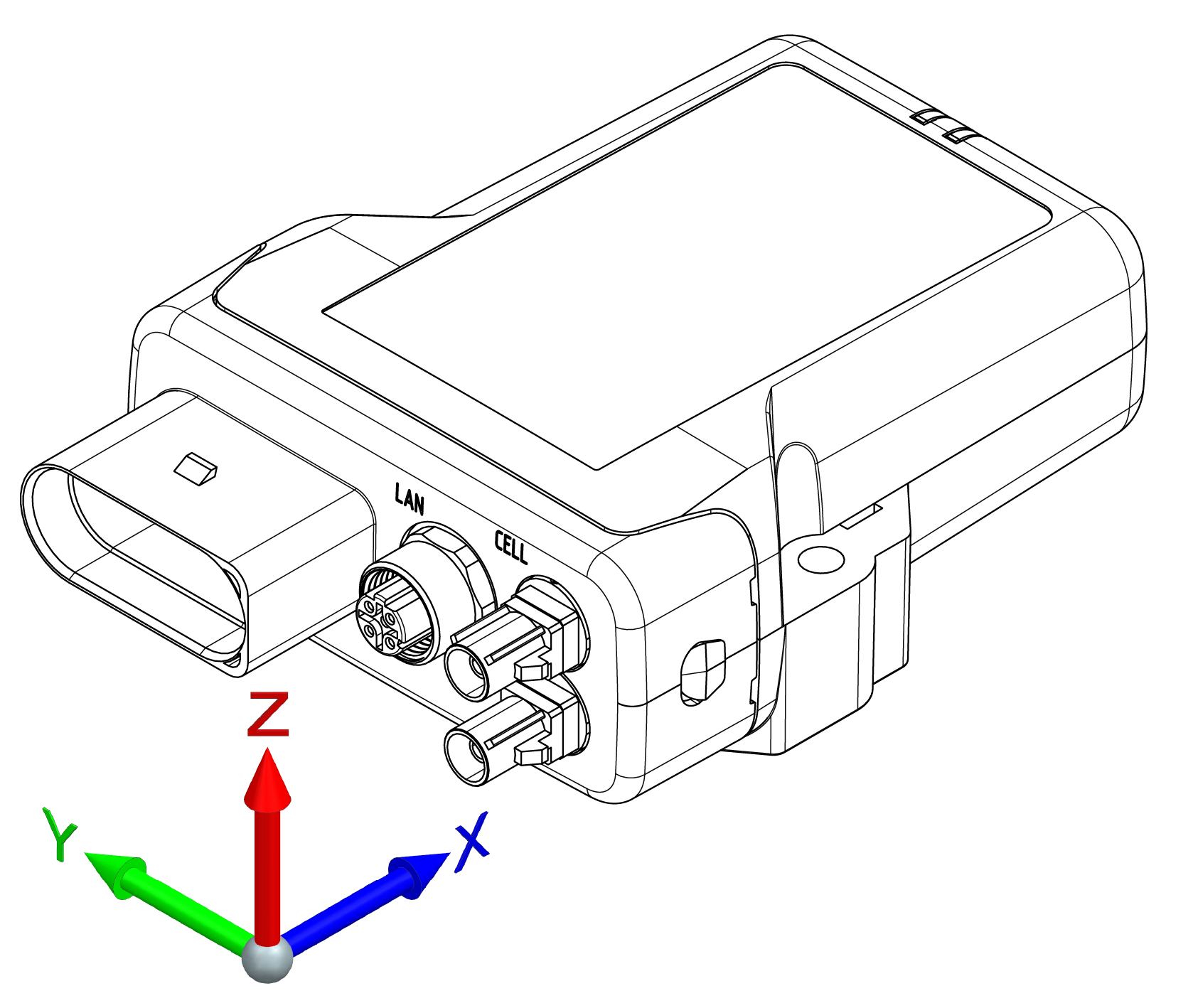
Acceleration Sensor
The acceleration sensor registers and evaluates accelerations in the directions of the X, Y, and Z axes, provides the measurements to the configuration logic and can send them via the CAN bus.
Note
Sensor is not calibrated.
Gyro Sensor
The 3-axis gyro sensor registers and evaluates the angle speeds in the X, Y, and Z axes, provides the measurements to the configuration logic and can send them via the CAN bus.
Note
Sensor is not calibrated.
GNSS - Global Navigation Satellite System
The device is equipped with a GNSS receiver. You can send the position data determined by the GNSS receiver via the CAN bus or the mobile radio network. The receiver can process signals from GPS, GLONASS and BeiDou satellites. It can process data from two navigation systems simultaneously. This increases the accuracy.
The GNSS-Signal is received via an external active antenna connected to an antenna connector.
Digital Output
The digital output is implemented as a high-side switch and switches Terminal 30 (supply voltage). The load must be connected to GND.
The output is protected by the over-current protection of an integrated smart high-side power switch.
There is no fuse in the output line. The maximum allowed load current is 500 mA.
If additional protection (e.g. a fuse) is required, it must be implemented externally by the customer (e.g. in the wiring harness).
Further electrical specifications can be found in the Annex.
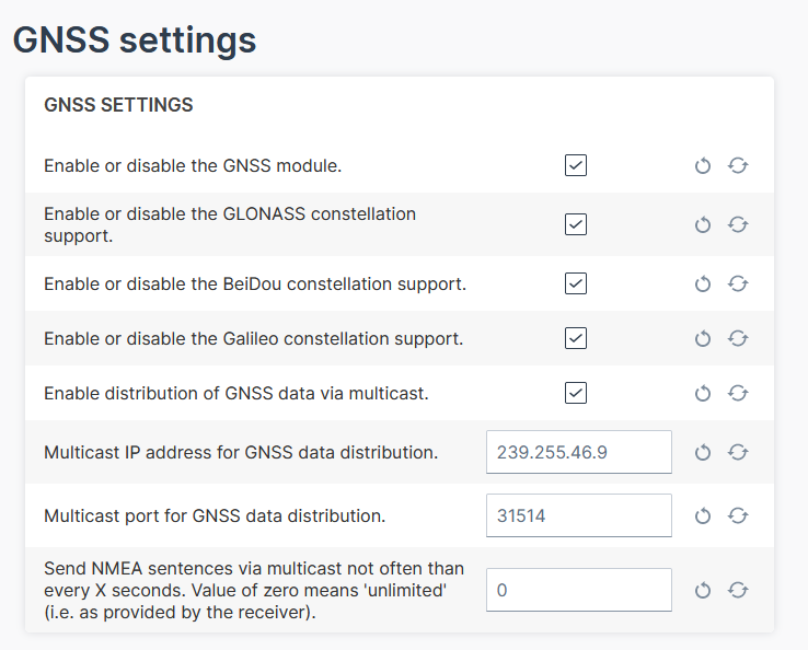
Configuration
In the Configuration Web User Interface via the Advanced Settings, you can configure following settings:
-
Enable the GNSS module, if not done yet.
-
Enable the GLONASS, BeiDou, Galileo as needed.
-
The distribution of GNSS data via multicast is enabled by default.
-
Adapt the IP address for the multicast, if needed.
-
Adjust the sending of NMEA frames as a multicast message by entering the interval in seconds.
Receive GNSS Multicast Messages
To receive the NMEA GNSS strings via Ethernet/IP shared by the device, the socket must join the multicast group.
The strings are raw NMEA sentences that are terminated by \r\n.
The strings include the position data, i.e. latitude/longitude, the number of satellites, the level.
For testing purposes, you can use a tool that listens to the incoming strings, e.g. Packet Sender or implement a listener on your own, see Receiving multicast messages.
Note
Make sure to connect the GPS antenna to the device and place the antenna outside or close to a window.
Note
Make sure that the computer and the device are on the same LAN for testing.
Note
You might need to open the port (by default 31514).
For Windows operating systems, there might be more settings to configure for multicast, e.g. the receiving interface.
eSIM card
All device types are equipped with an integrated eSIM card. On delivery, the eSIM card already has an eSIM profile with all the necessary communication settings.
Note
Potential connectivity loss with custom SIM card
The device cannot establish an online connection to the Proemion DataPlatform when using a customer specific eSIM card and wrong firewall settings at the SIM provider. IP addresses of the DataPlatform may change without prior notice.
- Make sure that the SIM card provider is not using IP address based white-listing for any DataPlatform communication.
- Make sure that - if white-listing is required - the corresponding DNS names are white-listed at the SIM provider's firewall.
Note
On delivery, the device's eSIM card is not yet activated. After registration of the CANlink® mobile 10000, activation of the eSIM card is triggered automatically. Usually this process takes about 15 minutes. In exceptional cases it can take up to 1 working day.
Nano-SIM card
The CANlink® mobile 10000 is equipped with a hinged nano-SIM card slot that is not accessible from the outside. This type is only available as a customer-specific variant, in which the nano-SIM card provided by the customer is already installed and tested at the Proemion factory.
Replace the nano-SIM card only if the device variant supports this feature and follow the procedure described in the Install the nano-SIM card. Use only approved tools and follow the specified instructions. Improper handling may damage the device and may affect warranty coverage.
Note
Potential connectivity loss with custom SIM card
The device cannot establish an online connection to the Proemion DataPlatform when using a customer specific nano-SIM card and wrong firewall settings at the SIM provider. IP addresses of the DataPlatform may change without prior notice.
- Make sure that the SIM card provider is not using IP address based white-listing for any DataPlatform communication.
- Make sure that - if white-listing is required - the corresponding DNS names are white-listed at the SIM provider's firewall.
Note
Potential connectivity loss with custom SIM card
Malfunction due to defective nano SIM may occur.
- Make sure that the specification of the selected nano-SIM card meets the environmental requirements of the CANlink mobile. Refer to Mechanical.
- Ensure that the dimension of the selected nano SIM is according to form factor 4FF.
Note
If a larger quantity of the CANlink® mobile 10000 with a specific nano-SIM card is required, please get in touch with your responsible sales contact person. A separate order number will then be created.