Configuration Web User Interface
The CANlink® mobile 10000 provides a local web server with a configuration web user interface (configuration web UI) allowing remote maintenance for configuring the network interface, device settings and settings regarding the file upload via the HTTP(S) method.
Access Configuration Web User Interface
Note
In order to access to the configuration web UI, a connection to the device must be established. Make sure that CANlink® mobile 10000 is on and available via the network.
To locally access the configuration web UI of the CANlink® mobile 10000, proceed as follows:
-
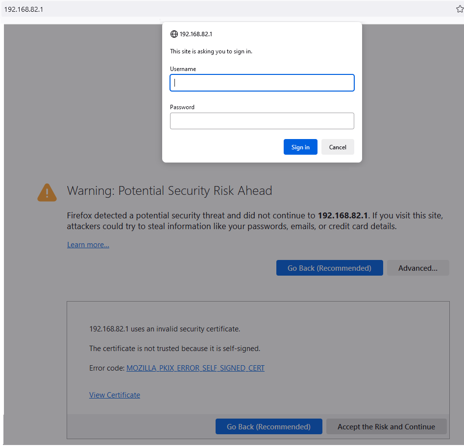
In the browser, type in the IP address
192.168.82.1(your local IP address might be a different one).Note
Your browser will show a security warning that you may ignore and "Accept the Risk and Continue".
-
A login window opens where you need to type in the credentials:
- The username is:
admin. - The initial password is provided on the Type Label of the device.
Note
Devices manufactured before August 1st, 2025, use the Ethernet MAC address as the initial password.
- The username is:
It is highly recommended to change the password after initial login, see Security.
In the configuration web UI you can then change between the following configuration menus:
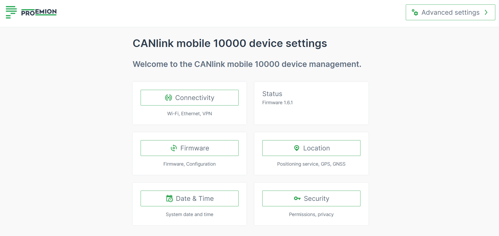
Connectivity
The Connectivity menu provides
- The Network menu for managing the interface/connection profiles for Cellular, Ethernet, WiFi and Virtual Ethernet-WiFi bridging.
- The Remote Machine Tunnel menu for managing the settings for the remote connection functionality.
Find also information on:
- Operation Mode
- Profiles: How to configure Cellular Network Profile, Virtual Ethernet-WiFi Bridging Network Profile, Ethernet Network Profile, WiFi Network Profile.
- How to use Ethernet Access Point with Internet Access, WiFi Access Point with Internet Access and Fallback strategies
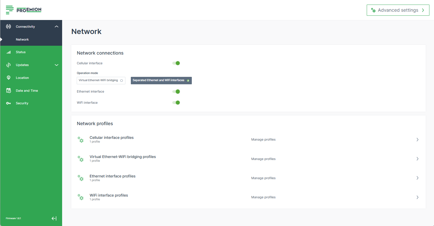
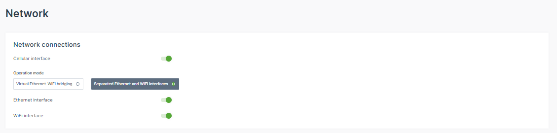
Network
In the Network menu you can configure the network interfaces for Cellular (Modem), Ethernet, WiFi and Virtual Bridging Interface to connect the CANlink® mobile 10000 to the DataPlatform.
You can also establish other connections like local direct connections to the device e.g. through WiFi access point.
Important
Toggling an interface, en-/disables the connection not only to the DataPlatform, but also the access to the configuration web UI via this interface.
Security Features
The CANlink® mobile 10000 includes traffic control and network monitoring mechanisms as part of compliance with the Radio Equipment Directive (RED), Article 3.3 (EN 18031). These mechanisms help protect the device and connected networks from unauthorized access and different kind of attacks.
In the following sections, the relevant settings are described for adding new profiles. The settings are available for each interface with some dedicated options described in the sections below.
The configuration web UI allows modifying network profiles even if the related operating mode is not active at that moment.
Operation Mode
You can change the Operation Mode to switch between the physical interfaces and the virtual (bridging) interface.
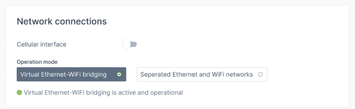
-
Toggle the Virtual Ethernet-WiFi bridging option to activate the virtual (bridging) interface.
Note
When the virtual (bridging) interface is active, the WiFi and the Ethernet interface are always enabled, i.e. cannot be deactivated.
-
Or switch to Separated Ethernet and WiFi networks to separate the individual, physical Ethernet and WiFi interfaces and to work independently of each other (consider adapting the WiFi and Ethernet profiles separately). You may disable an interface.
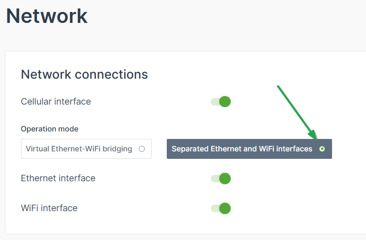
Figure 6: Separated Ethernet and WiFi interfaces Warning
Before switching the mode, make sure to have the profiles configured, otherwise the device might not connect if not configured well, e.g. the profile is still on “auto”.
Profiles
Consider the following conditions for the different profiles:
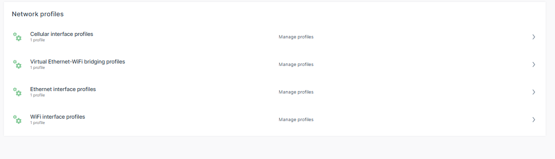
-
Only one profile per interface can be active at a time (even if several are enabled at the same time).
-
For each network interface, Cellular, Ethernet and WiFi, you have a default profile which you cannot delete but only edit.
-
You can add several new profiles with different settings.
To do so, click the plus icon:
Figure 8: New profile -
For each profile of the Cellular, Ethernet or WiFi network interface, you can define the Connection Priority: Enter an arbitrary, positive number - the higher value gives preference.
-
The Connection Priority prioritizes all interface profiles configured by the user for one specific interface.
-
Example: you set up 3 WiFi Interface Profiles for your Home Network, Company Network and Hotspot as fallback. You define the following Connection Priorities:
Home Network: 20
Company Network: 15
Hotspot: 10
If all profiles are set to "Automatically join this network when available" the CANlink mobile will first try to connect to "Home Network", if unsuccessful it will try to connect to "Company Network", if unsuccessful it will start the "Hotspot". This order is just for the WiFi interface. Cellular and Ethernet have their own independent orders of profiles. -
Example:
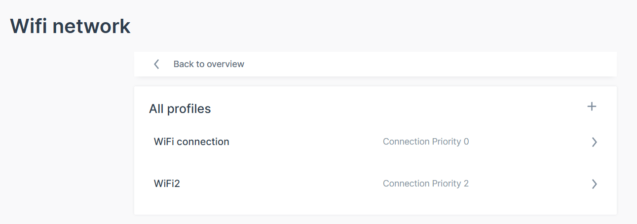
Figure 9: Connection Priority Example Note
For the Routing Metric, the lowest value will be used to route the traffic (e.g. Internet connection).
-
-
Cellular Network Profile
You can use the cellular network profile to establish a DataPlatform connection over the built-in cellular modem.
This can be used to:
- enable bi-directional remote communication with your machines.
- update certain components of the machines via cellular connection.
- use this Internet connection to authenticate to the DataPlatform to exchange relevant data.
- use the cellular modem to share Internet via WiFi and Ethernet, see WiFi Access Point with Internet Access and Ethernet Access Point with Internet Access.
Consider setting the cellular connection as the primary Internet connection, i.e. by changing the Operation Mode or the Lowest routing metric, see Advanced Settings.
The CANlink® mobile 10000 then connects to the provider via a cellular connection.
Add new Cellular Settings - Connection Profile
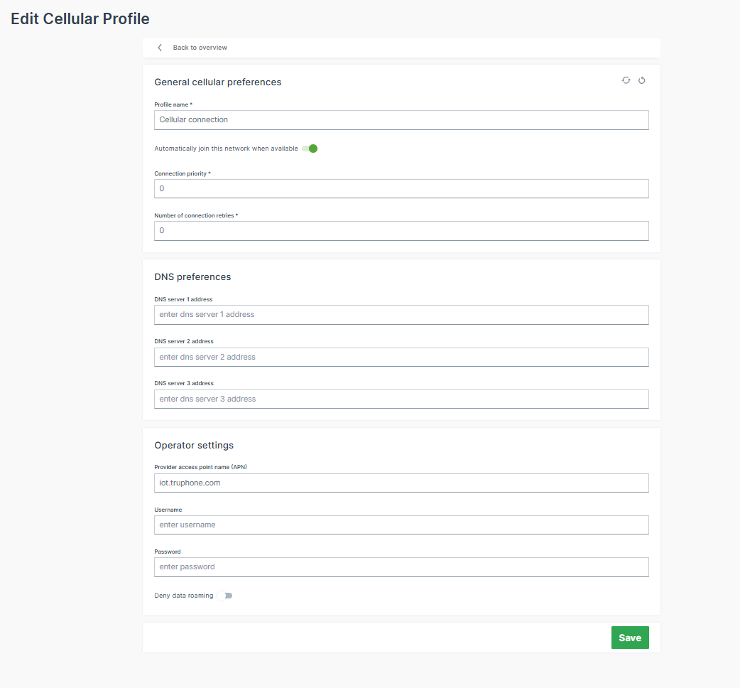
Note
Adjust the Cellular interface carefully considering the SIM traffic consumption.
- Profile name: Add a new profile name.
- Automatically join this network when available: When enabled, it activates this interface profile and takes care that the CANlink® mobile 10000 will try to connect to a network automatically.
- Connection priority: The higher the number (starting at
0), the higher the priority this interface profile is given over other profiles on the same interface for establishing a connection, see Profiles. - Number of connection retries: Specifies how many times a connection attempt should be made using this interface profile before the next interface profile is used according to the connection priority.
- Deny data roaming: To deny the data roaming is not recommended for international deployments as it would block any usage of the device in countries foreign to the SIM card.
- Via the Advanced Settings, you can adapt the SIM settings to enable the PIN (default: disabled).
Virtual Ethernet-WiFi Bridging Network Profile
With the Bridging interface active, Ethernet and WiFi are virtually linked and connected devices, whether via Ethernet or WiFi, are part of the same network and can communicate with each other.
A single IP address is configured with the Virtual Ethernet-WiFi Bridging Network Profile, which is used to set up the network other clients can connect to. The CANlink® mobile 10000 acts as the gateway to allow clients on both interface to communicate.
Thereby, you can avoid connecting Ethernet cables for diagnostics as access to Ethernet clients is possible via the WiFi interface.
Note
If the CANlink® mobile 10000 acts as a DHCP server, it must not be connected to a network with another DHCP Server to avoid network issues.
Exemplary application for the Bridging interface could be as follows:
Laptop -> WiFi Hotspot (CANlink® mobile 10000) -> Ethernet LAN (CANlink® mobile 10000) -> various devices in the network.
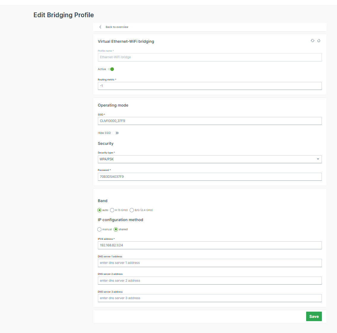
In the Virtual Ethernet-WiFi bridging you can configure the network profile for the Bridging interface (note that you configure only 1 profile, not multiple as in the other network connections):
- SSID: Name of the WiFi Access Point.
- IP configuration method:
- shared (default): The CANlink® mobile 10000 acts as the DHCP Server of the network assigning IP addresses to connected clients.
- The configured IP address (default:
192.168.82.1) is assigned to the CANlink® mobile 10000 and is used to set up the network. - The IP address and netmask must be entered according to the CIDR notation.
Example: If you want to set the IP address of the CANlink® mobile 10000 to192.168.82.1and the netmask to255.255.255.0, then you must enter192.168.82.1/24into the IP address field.
The CANlink® mobile 10000 also acts as a DHCP server in this "shared" method. That means, if you configured192.168.82.1/24via the IP address, the CANlink® mobile 10000 will assign IP addresses from192.168.82.2to192.168.82.254. - The range of the DHCP pool used for dynamic IP address assignment can be specified. This allows a range to be reserved for clients' static IP addresses.
- Allow internet access for connected clients: With this enabled the CANlink® mobile 10000 shares the Internet access with the network.
- The configured IP address (default:
- manual: The configured IP address will be used. But the CANlink® mobile 10000 does not act as a DHCP server.
- The DNS server settings are configurable.
- shared (default): The CANlink® mobile 10000 acts as the DHCP Server of the network assigning IP addresses to connected clients.
Note
The IP settings may be differently configured for the different profiles. Therefore, make sure to properly configure the profiles, when switching interfaces (see Operation Mode); otherwise you may lose the connectivity to the configuration web UI.
Ethernet Network Profile
The Ethernet Network Profile can be used to communicate with other devices accessible via Ethernet or even go online without the Cellular modem by making use of an already existing modem on the machine. Possible use cases are:
- Data transfer between devices.
- Access Internet via Ethernet connection when the Cellular connection is insufficient.
- Establish a DataPlatform connection over an Internet router connected via Ethernet.
The CANlink® mobile 10000 is always delivered with a unique Ethernet MAC address (accessible via the type label) and can be identified in your LAN network via the Ethernet MAC address.
Thereby, the IP address assigned by the DHCP server can be found out in case the CANlink® mobile 10000 is configured to act as a DHCP client on the Ethernet network, see profile settings below.
Note
When the Bridging interface option is active, the Ethernet interface is automatically enabled, see Operation Mode. The individual Ethernet interface profiles become invalid.
Add new Ethernet Settings - Connection Profile
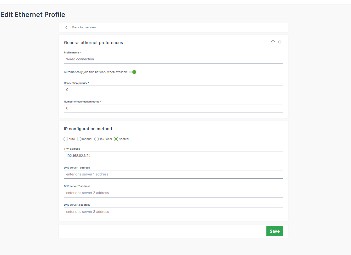
- Profile name: Add a new profile name.
- Automatically join this network when available: When enabled, it activates this interface profile and takes care that the CANlink® mobile 10000 will try to connect to a network automatically.
- Connection priority: The higher the number (starting at
0), the higher the priority this interface profile is given over other profiles on the same interface for establishing a connection, see Profiles. - Number of connection retries: Specifies how many times a connection attempt should be made using this interface profile before the next interface profile is used according to the connection priority.
-
IP configuration method:
- auto: CANlink® mobile 10000 acts as a DHCP client and gets IP address assigned by the DHCP Server (e.g., router or gateway on the machine).
- The DNS server settings are configurable.
- manual: The configured IP address will be used.
- Choose this option if a static IP address should be used.
- This can be used if there is no DHCP server on the network to assign an IP address or the CANlink® mobile 10000 must obtain a static IP address instead of having one dynamically assigned by the DHCP server. Please verify that the configured IP address is within the router's subnet.
- The DNS server settings are configurable.
- link-local: Link-local addressing (APIPA – Automatic Private IP Addressing) assigns an IPv4 address in the range
169.254.0.0/16when no DHCP server is available. This allows basic communication with devices in the same local network segment without requiring a DHCP server. - shared (default): The CANlink® mobile 10000 acts as the DHCP Server of the network assigning IP addresses to connected clients.
- The configured IP address (default:
192.168.82.1) is assigned to the CANlink® mobile 10000 and is used to set up the network. - The IP address and netmask must be entered according to the CIDR notation.
Example: If you want to set the IP address of the CANlink® mobile 10000 to192.168.82.1and the netmask to255.255.255.0, then you must enter192.168.82.1/24into the IP address field.
The CANlink® mobile 10000 also acts as a DHCP server in this "shared" method. That means, if you configured192.168.82.1/24via the IP address, the CANlink® mobile 10000 will assign IP addresses from192.168.82.2to192.168.82.254. - The range of the DHCP pool used for dynamic IP address assignment can be specified. This allows a range to be reserved for clients' static IP addresses.
- Allow internet access for connected clients: With this enabled the CANlink® mobile 10000 shares the Internet access with the network.
- The configured IP address (default:
- auto: CANlink® mobile 10000 acts as a DHCP client and gets IP address assigned by the DHCP Server (e.g., router or gateway on the machine).
Note
If the CANlink® mobile 10000 acts as a DHCP server, it must not be connected to a network with another DHCP Server to avoid network issues.
Ethernet Access Point with Internet Access
You can share the Internet access from the cellular or external modem via Ethernet. Proceed as follows:
- The CANlink® mobile 10000 is set up to go online via WiFi (see WiFi Network Profile) and/or via Cellular (see Cellular Network Profile).
- Configure the Ethernet interface as the interface that forwards/shares the Internet connection:
- Set the IP configuration method of the Ethernet to
sharedand configure it; thereby the CANlink® mobile 10000 also acts as the DHCP server on the Ethernet network. - Turn on the setting Allow internet access for connected clients.
- Connect the CANlink® mobile 10000 to an Ethernet network to become the Internet router with a DHCP server.
- Set the IP configuration method of the Ethernet to
- The CANlink® mobile 10000 uses the IP address configured by the user and assigns IP addresses to connected devices.
Now, every device connected to the shared Ethernet interface of the CANlink® mobile 10000 can access the Internet.
Note
For the shared option, you can choose one or both interfaces, WiFi and Ethernet, to share the Internet connection. But, the interface used by the CANlink® mobile 10000 to go online cannot share Internet access at the same time.
If, for example, the CANlink® mobile 10000 goes online over a WiFi network, then the WiFi interface of the CANlink® mobile 10000 cannot be used to share the Internet connection. However, sharing via Ethernet would work here.
If the CANlink® mobile 10000 goes online via the cellular modem, sharing Internet via WiFi and Ethernet is possible.
WiFi Network Profile
The WiFi Network Profile can be used to communicate with other devices accessible via WiFi or even go online without the Cellular modem by making use of an already existing modem on the machine. Possible use cases are:
- Data transfer between devices.
- Access Internet via WiFi connection when the Cellular connection is insufficient.
- Establish a DataPlatform connection over an Internet router connected via WiFi.
Note
When the Bridging interface option is active, the WiFi interface is automatically enabled, see Operation Mode. The individual WiFi interface profiles become invalid.
Add new WiFi Settings - Connection Profile
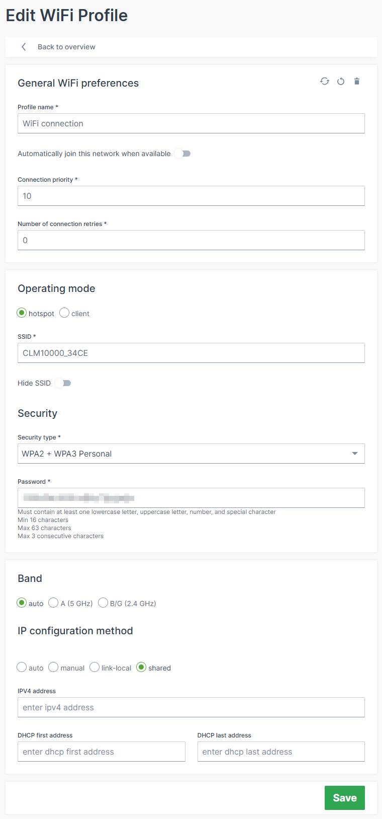
- Profile name: Add a new profile name.
- Automatically join this network when available: When enabled, it activates this interface profile and takes care that the CANlink® mobile 10000 will try to connect to a network automatically.
- Connection priority: The higher the number (starting at
0), the higher the priority this interface profile is given over other profiles on the same interface for establishing a connection, see Profiles. - Number of connection retries: Specifies how many times a connection attempt should be made using this interface profile before the next interface profile is used according to the connection priority.
- Operating mode: The CANlink® mobile 10000 can be used as a client or hotspot/AccessPoint; the hotspot mode allows clients to connect to the CANlink® mobile 10000 using the SSID and the password (e.g. WPA2/PSK). Consider also the IP configuration method Shared below.
- hotspot
- client
- SSID: Name of the WiFi Access Point.
- BSSID: not required; is the MAC address of the WiFi.
- Security: Choose the authentication method.
- IP configuration method: Choose the client communication type:
- auto: CANlink® mobile 10000 acts as a DHCP client and gets IP address assigned by the DHCP Server (e.g., router or gateway on the machine).
- The DNS server settings are configurable.
- manual: The configured IP address will be used.
- Choose this option if a static IP address should be used.
- This can be used if there is no DHCP server on the network to assign an IP address or the CANlink® mobile 10000 must obtain a static IP address instead of having one dynamically assigned by the DHCP server. Please verify that the configured IP address is within the router's subnet.
- The DNS server settings are configurable.
- shared (default): The CANlink® mobile 10000 acts as the DHCP Server of the network assigning IP addresses to connected clients.
- The configured IP address (default:
192.168.83.1) is assigned to the CANlink® mobile 10000 and is used to set up the network. - The IP address and netmask must be entered according to the CIDR notation.
Example: If you want to set the IP address of the CANlink® mobile 10000 to192.168.83.1and the netmask to255.255.255.0, then you must enter192.168.83.1/24into the IP address field.
The CANlink® mobile 10000 also acts as a DHCP server in this "shared" method. That means, if you configured192.168.83.1/24via the IP address, the CANlink® mobile 10000 will assign IP addresses from192.168.83.2to192.168.83.254. - The range of the DHCP pool used for dynamic IP address assignment can be specified. This allows a range to be reserved for clients' static IP addresses.
- Allow internet access for connected clients: With this enabled the CANlink® mobile 10000 shares the Internet access with the network.
- The configured IP address (default:
- auto: CANlink® mobile 10000 acts as a DHCP client and gets IP address assigned by the DHCP Server (e.g., router or gateway on the machine).
To connect the CANlink® mobile 10000 to a WiFi access point with DHCP server as a DHCP client, configure the following settings:
- Set Operating mode to client.
- Set SSID of the access point the CANlink® mobile 10000 should connect to.
- Choose for Security between WPA2 + WPA3 Personal or WPA3 Personal only (SAE) as the authentication method of the access point.
- Set the credentials based on the selected authentication method valid for the access point.
- Configure the IP configuration method of the CANlink® mobile 10000 to auto to act as a DHCP client on the WiFi network.
- The CANlink® mobile 10000 can now establish a connection to the configured access point and successfully authenticates; gets its IP address assigned from the DHCP server running on the access point;
- If the access point offers Internet access the CANlink® mobile 10000 can use this as access point to the Internet as well.
WiFi Access Point with Internet Access
You can share the Internet access from the cellular or external modem via WiFi. Proceed as follows:
- The CANlink® mobile 10000 is set up to go online via the Ethernet (see Ethernet Network Profile) and/or via Cellular (see Cellular Network Profile).
- Configure the WiFi interface to act as a hotspot/access point that forwards/shares the Internet connection.
- Set Operating mode to hotspot.
- Set up SSID Security for the hotspot.
- Set the IP configuration method of the WiFi to
sharedand configure it; thereby the CANlink® mobile 10000 also acts as the DHCP server on the WiFi network. - Turn on the setting Allow internet access for connected clients.
- The CANlink® mobile 10000 uses the IP address configured by the user and assigns IP addresses to connected devices.
You can now find and connect to the WiFi hotspot of the CANlink® mobile 10000 via a third-party device (e.g. a laptop) and can access the Internet.
Note
For the shared option, you can choose one or both interfaces, WiFi and Ethernet, to share the Internet connection. But, the interface used by the CANlink® mobile 10000 to go online cannot share Internet access at the same time.
If, for example, the CANlink® mobile 10000 goes online over a WiFi network, then the WiFi interface of the CANlink® mobile 10000 cannot be used to share the Internet connection. However, sharing via Ethernet would work here.
If the CANlink® mobile 10000 goes online via the cellular modem, sharing Internet via WiFi and Ethernet is possible.
Fallback strategies
Warning
The default priority of the different Network interfaces is as follows: Ethernet > WiFi > Cellular
Fallback to WiFi to get Internet access
- Configure the CANlink® mobile 10000 to be able to access the Internet via Ethernet, WiFi and the internal cellular modem - Make sure all configured network connections are reachable.
- To define the order the interfaces are used to connect to the Internet, the Routing Metric is used which is configured for each interface profile in the Advanced Settings.
- The profile with an active connection and the lowest routing metric will be used to establish the Internet connection. In this example, the Ethernet profiles are configured to have the lowest Routing Metric and therefore the CANlink® mobile 10000 establishes the Internet connection via the Ethernet interface.
- When The Ethernet connection of the CANlink® mobile 10000 drops for some reason and the WiFi interface has the next higher Routing Metric the CANlink mobile routes the Internet traffic automatically to the WiFi interface.
- The CANlink® mobile 10000 uses the WiFi connection for Internet connection until the Ethernet interface is available for the Internet connection again.
Note
You may use the Connection Priority to define a prioritized order of the interface profiles for one interface (e.g. the Ethernet interface) to establish a connection.
In case one Ethernet profile is not valid to establish a connection to the network the next Ethernet profile will be used and so on. But there might not be Internet connectivity on the network or it might not be used.
Note
If the Ethernet connection drops and the WiFi interface has the next higher Routing Metric, the CANlink® mobile 10000 routes the Internet traffic automatically to the WiFi interface.
Fallback to the internal cellular modem to get Internet access
- Configure the CANlink® mobile 10000 to be able to access the Internet via Ethernet, WiFi and the internal cellular modem. - Make sure all configured network connections are reachable.
- The CANlink® mobile 10000 establishes an Internet connection via the Ethernet interface based on the lowest Routing Metric for the Ethernet interface profile.
- Set up the Cellular interface profile to have the next higher Routing Metric.
- When The Ethernet and WiFi connection of the CANlink® mobile 10000 drop for some reason, the CANlink® mobile 10000 automatically switches to use the internal cellular modem for the Internet connection - provided that the Cellular interface profile used to establish the connection has the next higher Routing Metric than for the Ethernet connection that just dropped.
Remote Machine Tunnel
In the Remote Machine Tunnel menu you can configure whether this service should be enabled and allow remote connections to the machine.
Updates
Under Updates, you find the menus
- Firmware
- Configuration
Firmware
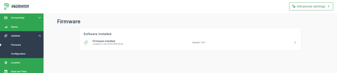
In the Firmware menu you can update the application firmware and view the history of the currently installed firmware.
You find the information about the installed firmware version also at the top and in the bottom left corner of the sidebar.
To upgrade the firmware, proceed as follows:
- Open the Updates > Firmware menu.
- Click in the field of the latest firmware to open the Upgrade firmware page.
- You can upload the firmware file of the format
.swu. - Click Install to upload the file and start the upgrade process. A message about the pending process will be displayed.
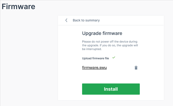
✓ When the firmware upgrade was successful, the configuration web UI will be reloaded and success message will be displayed. The installed firmware will be then listed in the Firmware menu.
Configuration
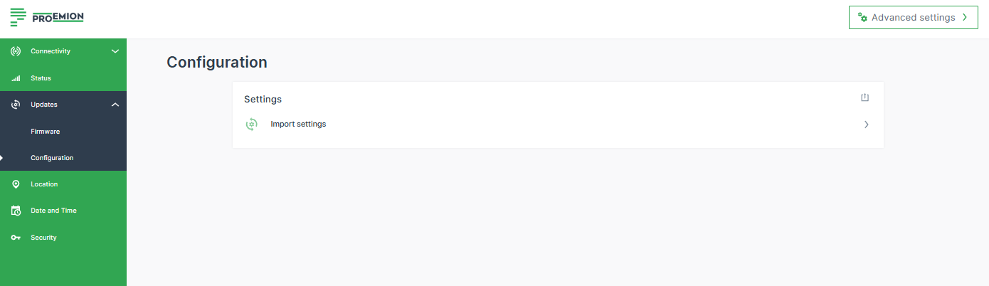
In the Configuration menu you can either update (import) the configuration or export the configuration settings.
All the configuration made via the Web UI are stored in a .clm file.
Note
The configuration file does not include the CODESYS application. A connection to this could be done via the Remote Machine Tunnel connection (connecting to the device as if it is on your network; device connected to the DataPortal via the mobile network).
Export Settings
To export the configuration settings, on the upper-right, click the export icon ![]() .
.
This configuration file can then be uploaded to the DataPortal via Settings > Configuration Bundle > +Add new configuration: Upload CLM10K files
This way, you could use configuration-over-the-air (COTA) for applying the configuration file to the fleet.
Import Settings
You can upload a configuration file to apply it on one device.
To upload a configuration file, proceed as follows:
- Open the Updates > Configuration menu.
- Click in the field Import settings.
- You can upload the configuration file of the format
.clm. - Click Install to upload the file and start the upgrade process.
✓ When the configuration upgrade was successful, the success message will be shown.
Location
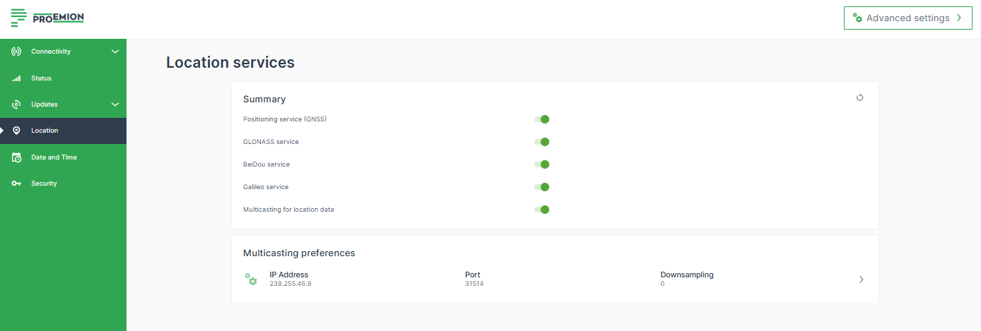
In the Location menu you can generally enable/disable the Positioning service (GNSS).
If enabled, the GPS service will be enabled by default.
In addition, you can enable other location services, e.g. Galileo service.
Date and Time
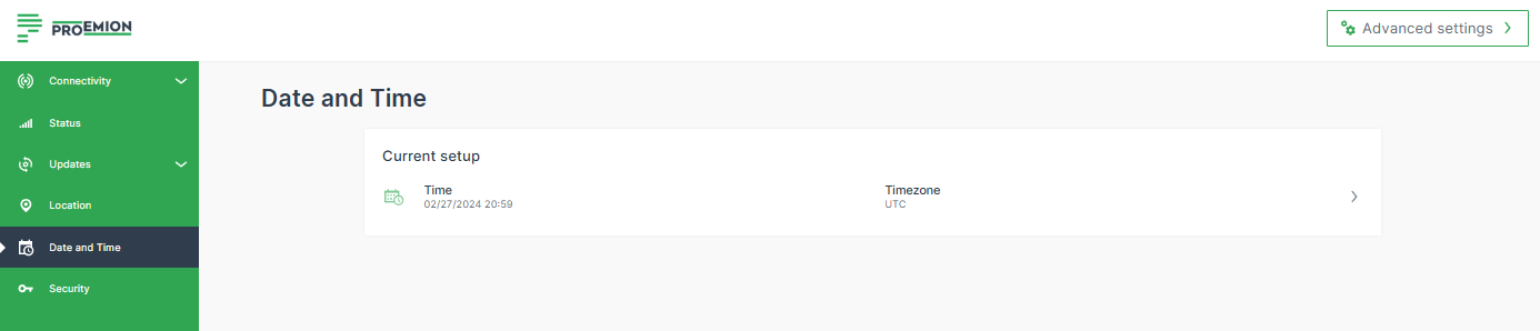
In the Date and Time settings, you can manually set the time together with the time zone or receive them automatically.
By default, the CANlink® mobile 10000 uses the Network Time Protocol (NTP) to automatically synchronize the system time via the Internet.
For this purpose, the device opens UDP port 123, which is required for communication with NTP servers.
Ensure that UDP port 123 is open in your network environment to allow proper time synchronization.
If needed, NTP-based time synchronization can be disabled under Advanced Settings > Date and Time.
The option to manually adjust the time is provided for use cases where the machine is located in an area where the time and time zone cannot be reliably retrieved automatically.
Note
The change of Date and Time settings is applied system-wide in the CANlink® mobile 10000. It might need an Internet connection for the changes to apply.
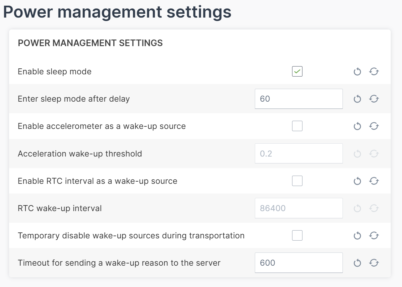
Power Management
In the Power Management menu, you can activate the option Enable sleep mode and configure its settings. For detailed information refer to the chapter Power management.
Security
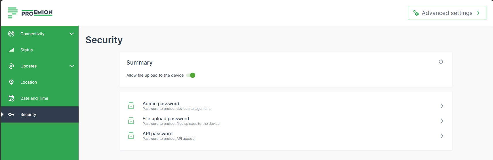
In the Security settings, you can change the password for the admin, upload and api users.
File upload can be deactivated by disabling the Allow file upload to the device option. Once disabled, files can no longer be pushed to the CANlink® mobile 10000 via the device JSON API endpoint and consequently not to the DataPlatform either.
| User | Configuration Web User Interface Access | Device’s JSON API Access |
|---|---|---|
| admin | Yes. | Yes. |
| api | No. | Yes, limited scope. |
| upload | No. | Yes, only file upload endpoint. |
Diagnostics
For troubleshooting and support, you can download a system log file directly from the CANlink® mobile 10000 configuration web UI.
Prerequisites
To downloading the system log file, ensure that you are either:
- Connected locally to the CANlink® mobile 10000 and logged in to the configuration web UI, or
- Connected remotely to the CANlink® mobile 10000 through the Remote Machine Tunnel.
To download the system logs, open the following URL in your browser:
https://< ip-address-of-the-device >/logs
Example:
https://192.168.82.1/logs
Note
Generating the log archive runs in the background and can take up to 30 seconds. No progress indicator is displayed. The download starts automatically when the archive is ready.
The system log file is downloaded as a compressed archive named logs-latest.tar.gz.
The archive contains the following information:
- Timestamp indicating when the archive was created
- Device configuration
- CODESYS logs
- For each boot partition:
- System logs and messages
- Proemion application information
- Filesystem and memory usage information
If requested, share the archive with Service and Support to assist with troubleshooting.
Advanced Settings
In the Advanced Settings, you may adapt the settings described above and configure more details, e.g. routing metric:
You can define the Routing metric used to make a routing decision. for each interface.
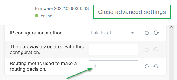
This option can be used to define/reorder the default routing, i.e. the preferred network the CANlink® mobile 10000 will choose for connecting to the DataPlatform.
The default value -1 means that the metric is chosen automatically.
Note
Make sure that other settings are adjusted accordingly in order to change the priority, e.g. en-/disabling the interface or the Autoconnect priority. etc.
Example of adjusting the routing metric:
- Enter an arbitrary, positive number for the routing metric of the interfaces. The lower value gives preference, e.g.:
- Ethernet routing metric: 100
- WiFi routing metric: 200
- Cellular routing metric: 300
- If you want the device to prefer the Cellular interface, change only the Cellular routing metric for instance to
10; the other interface remain as is, i.e Ethernet 100, WiFi 200.