CANlink® mobile 10000 Device Description in CODESYS
Starting with firmware version 3.3.0, the CANlink® mobile 10000 supports a CODESYS Device Description file, which defines how the device is represented in CODESYS and provides access to its inputs, outputs and internal sensors.
The file is preconfigured and works without user modification once added to a project.
However, you may need to manually install the required ExtensionAPI (CODESYS) library:
- The ExtensionAPI library is referenced by the IoDrvSocketUnix library.
- It is required to use the provided Device Description file in your application.
- Although the IoDrvSocketUnix library is automatically added when you include the Device Description file, the ExtensionAPI library may not be installed by default in your CODESYS Development System.
If the library is missing, the Development System will display an error.
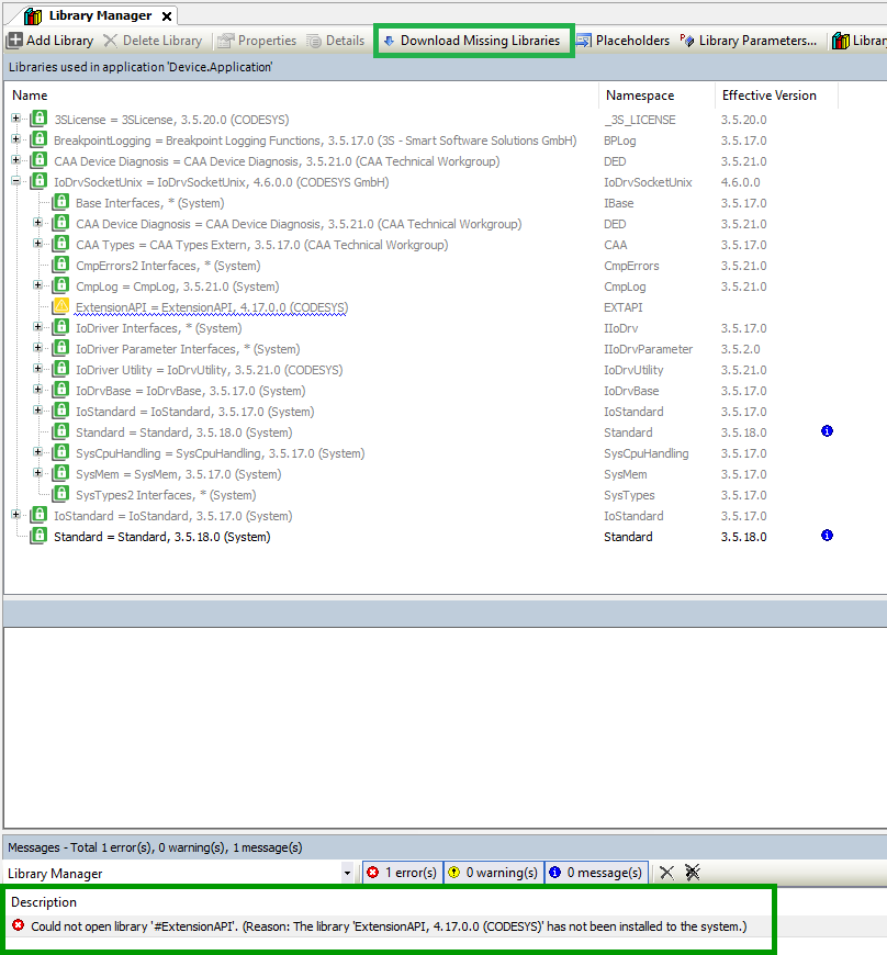
To resolve this:
- Open the Library Manager in CODESYS.
- Search for ExtensionAPI.
- Download and install the library if it is not already available.
Access signals
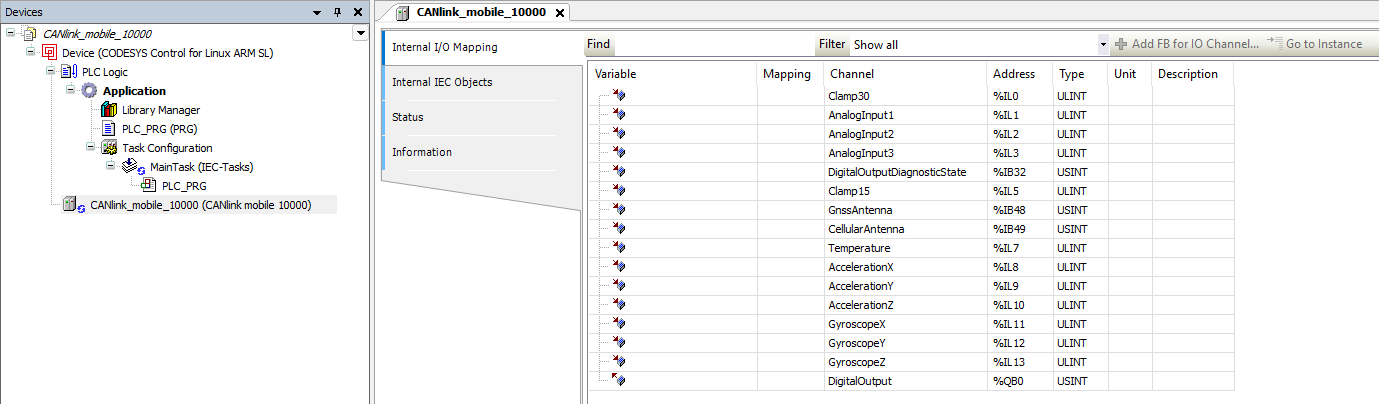
After adding the device to the project, the following explains where its signals can be found within CODESYS.
Add the device to your project and open the device tree. Signals are available via I/O Mapping or device variables (e.g., Clamp30, analog inputs, temperature).
Understand data representation and conversion
In the CODESYS environment, the ExtensionAPI uses ULINT as a universal container for 64-bit data.
Since LREAL (double precision floating-point) values are not directly supported in this context, measurement values are provided as ULINT and must be interpreted accordingly.
To access the original floating-point values, the 64-bit data is reinterpreted as LREAL.
In CODESYS, this is typically done using a UNION, which allows accessing the same memory as both ULINT and LREAL without modifying the underlying value.
This approach ensures that no data is lost, as the conversion is a bitwise reinterpretation of the same value.
Signals represented this way:
- Clamp30
- Clamp15
- Analog inputs
- Internal temperature
- Gyroscope values
- Accelerometer values
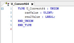
The following example shows how a value received from the device as ULINT is reinterpreted as LREAL using a UNION.
Example:
TYPE U_Convert64 : UNION
    rawValue : ULINT;
    realValue : LREAL;
END_UNION
END_TYPE
VAR
    converter : U_Convert64;
    result : LREAL;
END_VAR

converter.rawValue := InputValueFromDevice;
result := converter.realValue;
The screenshot below shows this approach in the CODESYS Development System.
A ULINT value is assigned to the UNION and accessed as LREAL without modifying the underlying data.
Check signal units
After reinterpretation, the signals correspond to the following physical units.
| Signal | Unit | Notes |
|---|---|---|
| Clamp30 | V | ULINT → LREAL |
| Clamp15 | V | ULINT → LREAL |
| Analog inputs | V | ULINT → LREAL |
| Internal temperature | °C | ULINT → LREAL |
| Gyroscope values | °/s | ULINT → LREAL |
| Accelerometer values | g | ULINT → LREAL |
| Digital output | bool | TRUE = outputs Clamp30 |
Interpret antenna status
The following values indicate the status of the cellular and GNSS antennas.
| Value | Meaning |
|---|---|
| 0 | Unknown |
| 1 | Not connected |
| 2 | Connected |
| 3 | Short circuit |
These values can be mapped to an enumeration for improved readability.
CODESYS example:
TYPE AntennaState :
(
    Unknown        := 0,
    NotConnected   := 1,
    Connected      := 2,
    ShortCircuit   := 3
) USINT;
END_TYPE
Use the digital output
The digital output can be controlled via a boolean value:
TRUEenables the output and applies the Clamp30 supply voltageFALSEdisables the output
The diagnostic state provides additional information about the output condition.
| Value | Meaning |
|---|---|
| 0 | No problems |
| 1 | Problem detected |
In case of an error, the output is automatically disabled and temporarily blocked to prevent overheating.
These diagnostic values can also be represented using an enumeration.
CODESYS example:
TYPE DOUTDiagnosticState :
(
    NoProblems        := 0,
    ProblemsDetected  := 1
) USINT;
END_TYPE