Functional conditions
Consider the electrical conditions described below and also in the Technical Data including the overload protection.
Antenna Positioning
For optimal reception of Bluetooth, Wi-Fi®, and cellular signals, ensure that radio waves are not obstructed by housing parts or surrounding objects.
Ensure that radio signals are not obstructed by labels, objects, or surrounding structures.
- Only mount the device in the installation position shown in Mount the Device.
- Choose a mounting location with minimal obstructions to ensure reliable communication.
- Do not apply additional labels to the device, as certain materials may significantly reduce signal quality.
- Do not modify the device or its surroundings in a way that affects antenna performance.
- The system integrator is responsible for ensuring adequate antenna performance and compliance with applicable regulations.
Antenna spacing
Maintain sufficient distance between antennas to avoid interference.
- The distance between antennas should be greater than 1/4 of the wavelength
- Avoid distances that are multiples of the wavelength
- When using multiple antennas, base the minimum distance on the lowest frequency
Example:
If using GNSS and Wi-Fi® antennas, maintain a minimum distance of 4.8 cm between antennas.
Internal Antennas
Internal antennas are installed inside the housing on the top of the device.
For the best possible reception of GNSS, Bluetooth, Wi-Fi® and mobile radio signals, the device should be mounted in the position shown here.
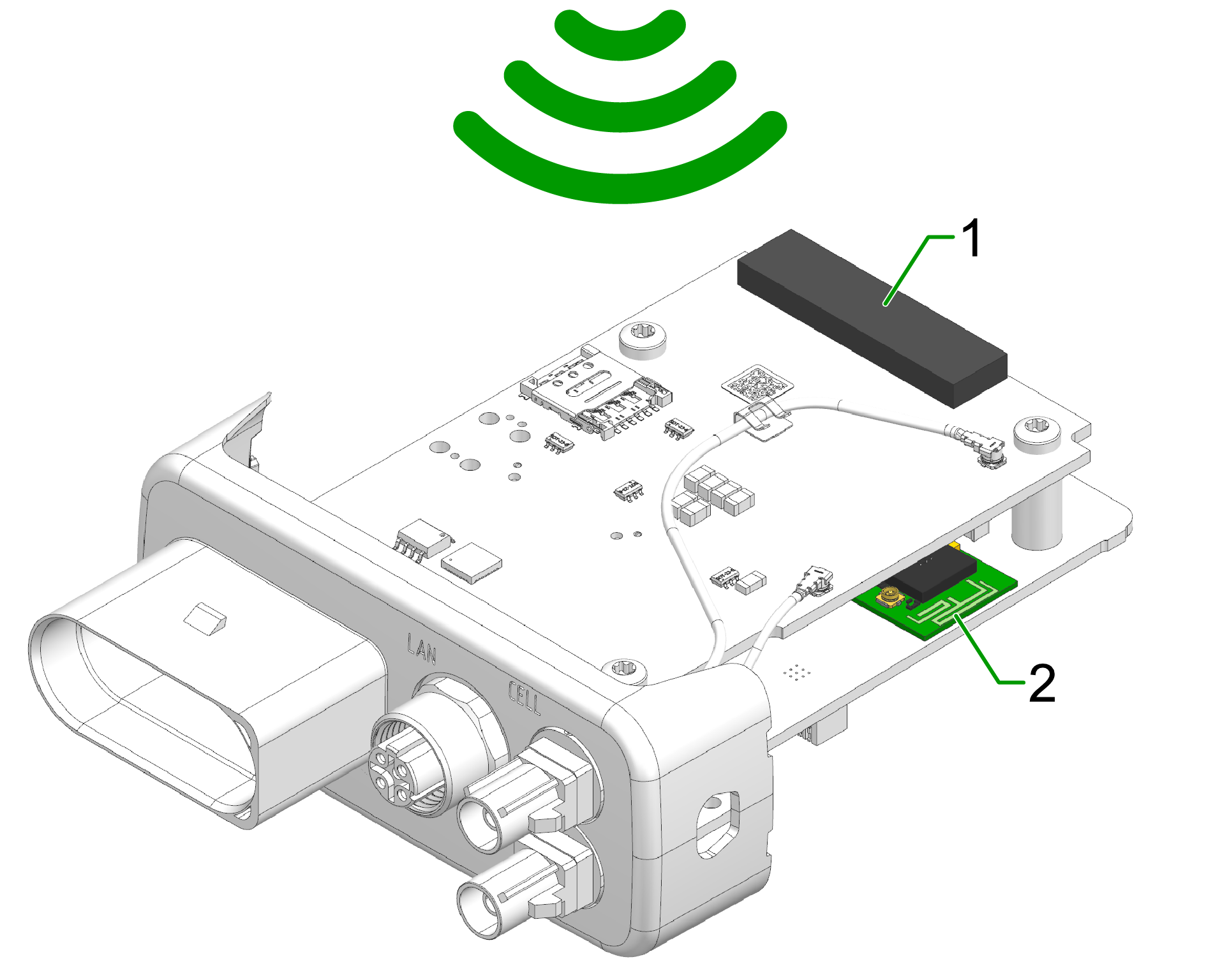
- Diversity cellular antenna
- Main cellular antenna (only for types )
- Wi-Fi / Bluetooth antenna
- GNSS antenna (only for types)
External Antennas
The following information applies to device variants with external antenna connectors.
For information on connector types, pin assignments, and instructions to connect and disconnect the antenna cables, refer to the Connectors chapter.
Refer also to the Safety Instructions for applicable safety requirements.
Antenna installation
Improper antenna installation may reduce cellular communication and GNSS performance.
- Use only approved antennas which are supplied as accessories by Proemion.
- Optimize the mounting position to reduce the distance between the antenna and the device or order an alternative antenna with longer antenna cable.
- Do not extend the antenna cable.
- Ensure that the minimum bending radius of the antenna cables is at least 8 times the outer diameter.
GNSS Antenna
Use only active GNSS antennas with LNA.
For detailed electrical specifications, refer to the CANlink mobile 3600 Datasheet.
For connector details, refer to the GNSS Antenna Interface.
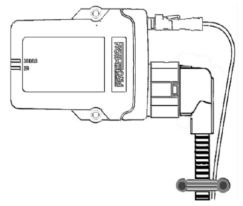
Cable Management
The following chapter describes how to install the cable harness and how to handle custom cabling.
Before starting the installation, read how design the correct electrical connection in Connectors and how to connect the cable to the device in Cables.
Proceed as follows:
Note
Adhere to the following instructions to avoid a malfunction of the device. Problems with the mobile network connectivity can be caused by an insufficient antenna setup and bending radius of the cables.
By that there is a risk of damaged cables and also water penetration due to incorrect assembly of the cable and missing sealing.
-
Assemble the cables in accordance with the recommendation of the manufacturer.
-
When mounting the device, please make sure that there is an adequate bending radius of the cables.
-
Ensure that there is a minimum bending radius of 8 times the outer diameter of the antenna cables.
-
Install strain reliefs for the cables.
-
Fasten the cable harness with a suitable strain relief near the main plug connector in order to avoid the transmission of any tension, strains or vibrations to the main plug connector and the housing.
-
Protect and fix the cables within the machine.
Connectors
For the connection to the device, several connectors are provided that require certain handling of the cables. The main chapter Connectors provides detailed information on connector type, pinning, etc. for the following connectors:
- X1 - Main Plug Connector
- X2 - Service Interface only for CANlink® mobile 3600
- X3 - Cellular Antenna Connector (mobile radio antenna connector)
- X4 - GNSS Antenna Connector
Cables
Different types of cables are used for the mentioned connectors. The following cables are supplied by Proemion:
- Starter cable for main plug connector only for CANlink® mobile 3600; covering also: Starter cable for main plug connector, individual wires open
- USB Connector Cable - Diagnostic only for CANlink® mobile 3600
The chapter Cables provides more information on the different cables and their cable ends.
Tip
Refer to Custom Cable for Main Plug for information on how to integrate the device into a custom cable harness on the machine.
Custom Cable for Main Plug
When creating a customized cable harness for the system integration of the CANlink® mobile 3600, CANlink® wireless 4000, or CANlink® mobile 10000, some important recommendation for the setup of the main plug connector and cable must be considered.
It is recommended to use the connector components included in the Connector Kit, see Launch Kit to create a custom cable harness.
Note
Risk of property damage.
- This chapter contains some important advices. Please follow the instructions from the connector manufacturer and general rules for creating and protecting cable harnesses.
Note
Risk of property damage.
Water penetration due to capillary action of the cable strands.
- Ensure that both ends of the cable strands are sealed and assembled in the correct manner and in accordance to the manufacturer's specifications.
| Product | Recommendation |
|---|---|
 |
For the cable assembly it is essential that the instructions from the handling manual of the connector supplier are followed. Especially the main sealing, wire sealing and dummy plugs must be installed in the right manner. Refer to Automotive Connectors/DeyTrade Connecting - Handling Manual FEP Sealed Connectors. |
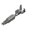 |
Use only the recommended tooling for machine processing. Refer to Connector Kit Datasheet. It is recommended to use tinned contacts. This corresponds the material of the pins |
 |
Use the wire sealing which fits to the outer diameter of the used wires |
 |
Cover the unused contact sockets with dummy plugs to protect the connection from dust and humidity |
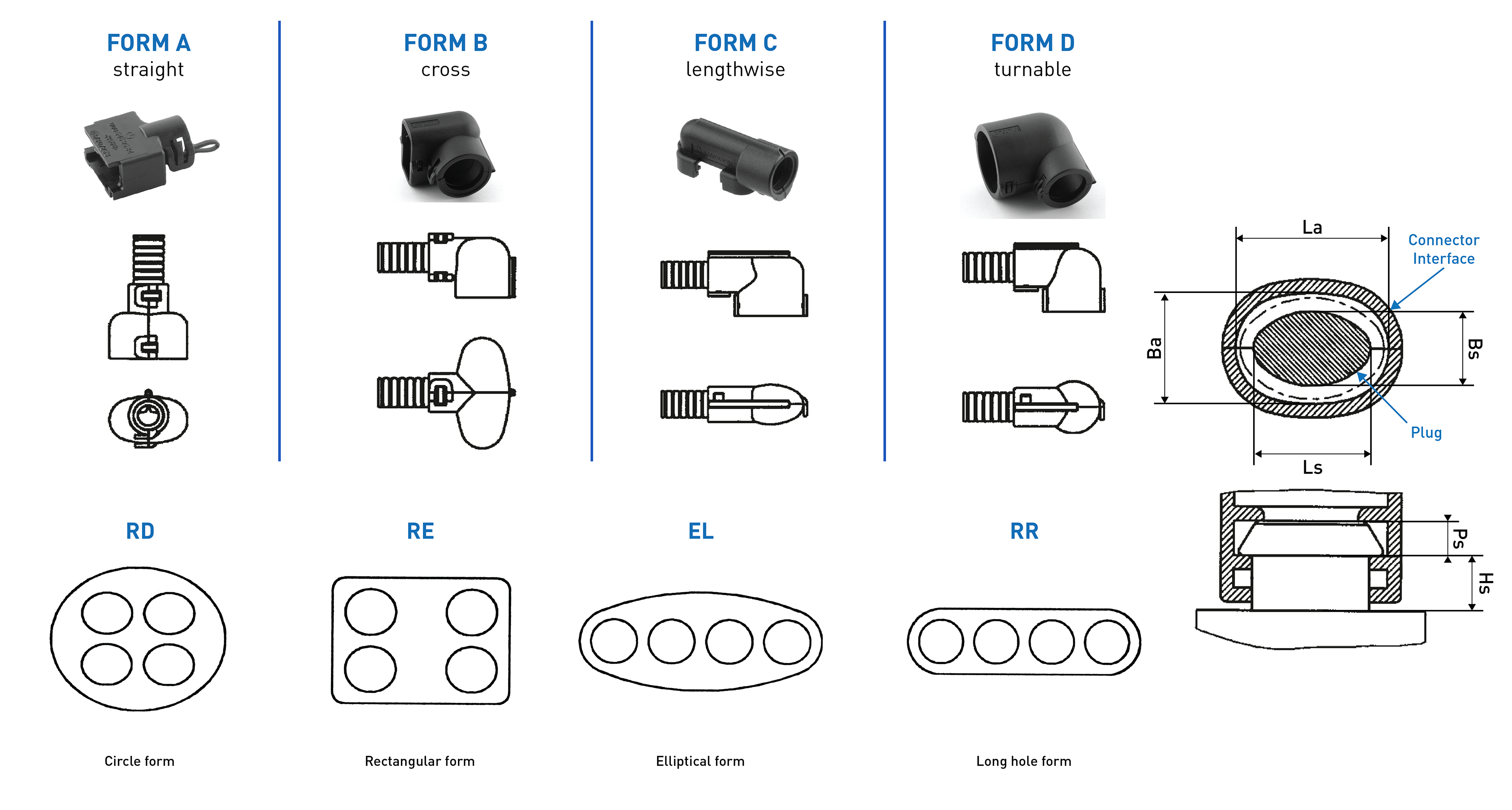
Protective Cover
Protect the connector and the cable with sufficient covers and cable tubing:
Warning
The following parts are not distributed by Proemion and can only be requested from the manufacturer with a minimum order quantity of 500 units, see Schlemmer.
The following part numbers from the supplier Schlemmer are recommended for the protective cover: 7807174, 7807207, 7807624: