CANlink® mobile 10000 Quick Start
Introduction
The following document helps you to get onboarded on the CANlink® mobile 10000 including its CODESYS application.
The chapter Getting Started describes the first steps required for deploying the device. Furthermore, it contains useful information on how to connect, configure, and mount the device.
The chapter CODESYS Development System describes the preparations to start the CANlink® mobile 10000 development with CODESYS.
Getting Started
Connecting the Device
When connecting the device to a PC, it may be helpful to use a USB-to-Ethernet adapter, as many PCs have only a single Ethernet port. It is also recommended to connect the device via Wi-Fi if a wired connection is not available.
To protect the device from damage and data loss, a correct wiring and configuration of the power management settings is mandatory. The main purpose of the power management settings is that the device has a safe shutdown before the supply voltage (terminal 30/31) is disconnected.
Warning
Overload damage due to malfunction.
Risk of severe or fatal injury.
- To limit power in the event of malfunction, secure the DC power supply circuit during installation with an external 2 A fuse.
Risk of property damage
- The device must be installed, connected, and commissioned by a qualified technician.
- Ensure the power supply is disconnected before connecting the device.
- Only use components from the launch kit or the accessories supplied. Refer to chapters Launch Kit and Software and Accessories.
If you have any questions or anything is unclear, please contact our support before getting started. See Service and Support.
Note
Device defect due to power failure.
Destroyed hardware component on the device. Repair not possible.
Destroyed file system on the device. Repair by Proemion necessary.
- Permanently connect terminal 30 to steady power supply (vehicle battery) to ensure that the required power management settings can be applied to the device in the right manner.
- Permanent disconnection from the power supply is only permitted when the device was set to sleep mode before.
- Connect terminal 15 correctly and configure secure switching to sleep mode in the Power Management section of the device configuration.
- Do not disconnect the device from the power supply until it has completely switched to sleep mode (all LEDs off).
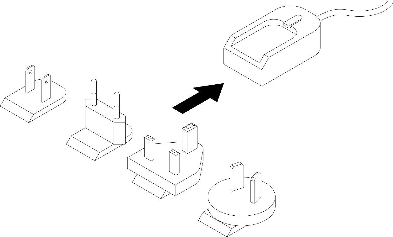
Power Supply
The main plug connector supplies the device with power. If you use the power supply unit from the kit, make sure you use the country adapter for your country.
Below you will find instructions on how to mount the device.
To ensure the housing provides proper fire protection and to achieve the best possible reception of radio signals, make sure you install the device in the correct position.
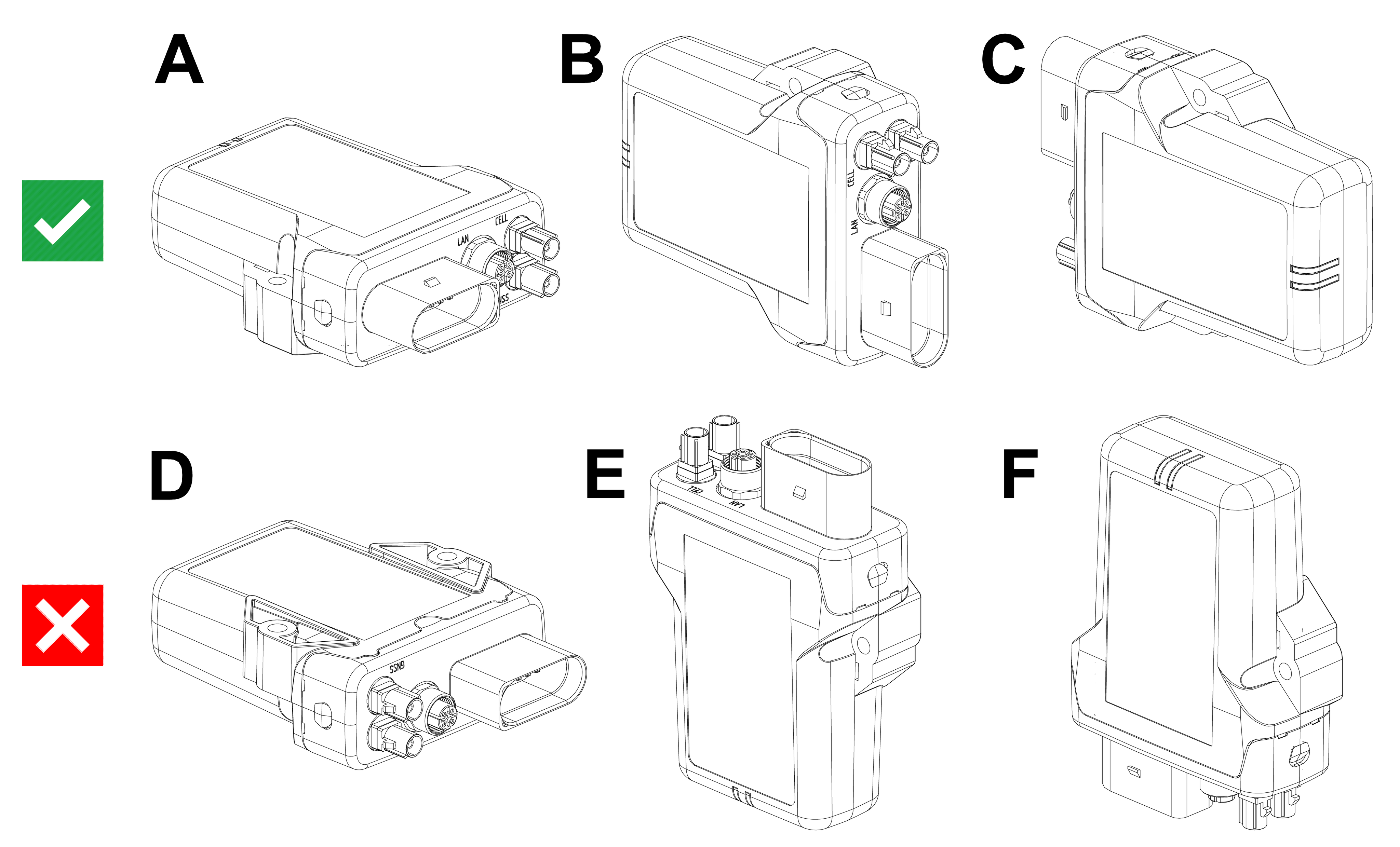
Mounting Orientation
The view elements of the two LEDs on the device do not comply with the flammability class required for a fire protection housing.
Note
Fire protection of the housing is only guaranteed in the installation positions shown in figures A, B or C or F.
Note
Please note that fire protection is not guaranteed in the installation positions shown in figures D and E.
Note
The mounting position F fulfills the requirements of a fire protection enclosure. But is not recommended due to possible liquid ingress.
Note
To avoid water ingress, please make sure that the mounting orientation of your device is either as shown in figure A, B or C.
Note
Risk of property damage.
- The device can be mounted with the plugs pointing to the left or right. Mounting with the plugs pointing up is not permitted. Mounting with the plugs pointing down is not recommended due to the risk of water ingress.
- Only mount the device in one of the installation orientations shown in this chapter.
- The device is protected against mechanical impacts according to class IK07 (IEC62262 impact energy 2 joules). To achieve a higher class, you must provide external protection when installing the device
Functional conditions
Consider the electrical conditions described below and also in the Technical Data including the overload protection.
Antenna Positioning
For optimal reception of Bluetooth, Wi-Fi®, and cellular signals, ensure that radio waves are not obstructed by housing parts or surrounding objects.
Ensure that radio signals are not obstructed by labels, objects, or surrounding structures.
- Only mount the device in the installation position shown in Mount the Device.
- Choose a mounting location with minimal obstructions to ensure reliable communication.
- Do not apply additional labels to the device, as certain materials may significantly reduce signal quality.
- Do not modify the device or its surroundings in a way that affects antenna performance.
- The system integrator is responsible for ensuring adequate antenna performance and compliance with applicable regulations.
Antenna spacing
Maintain sufficient distance between antennas to avoid interference.
- The distance between antennas should be greater than 1/4 of the wavelength
- Avoid distances that are multiples of the wavelength
- When using multiple antennas, base the minimum distance on the lowest frequency
Example:
If using GNSS and Wi-Fi® antennas, maintain a minimum distance of 4.8 cm between antennas.
Internal Antennas
Internal antennas are installed inside the housing on the top of the device.
For the best possible reception of GNSS, Bluetooth, Wi-Fi® and mobile radio signals, the device should be mounted in the position shown here.
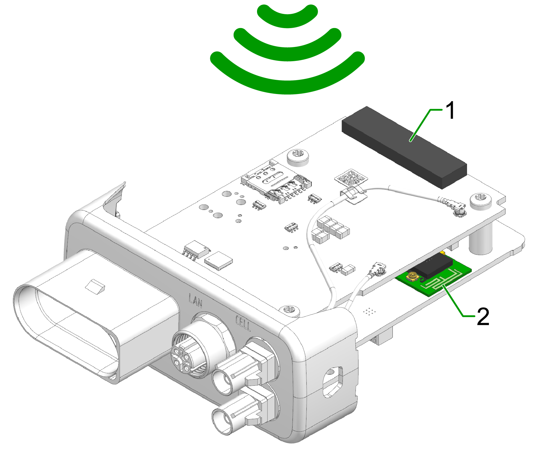
- Diversity cellular antenna
- Main cellular antenna (only for types )
- Wi-Fi / Bluetooth antenna
- GNSS antenna (only for types)
External Antennas
The following information applies to device variants with external antenna connectors.
For information on connector types, pin assignments, and instructions to connect and disconnect the antenna cables, refer to the Connectors chapter.
Refer also to the Safety Instructions for applicable safety requirements.
Antenna installation
Improper antenna installation may reduce cellular communication and GNSS performance.
- Use only approved antennas which are supplied as accessories by Proemion.
- Optimize the mounting position to reduce the distance between the antenna and the device or order an alternative antenna with longer antenna cable.
- Do not extend the antenna cable.
- Ensure that the minimum bending radius of the antenna cables is at least 8 times the outer diameter.
GNSS Antenna
Use only active GNSS antennas with LNA.
For detailed electrical specifications, refer to the CANlink mobile 3600 Datasheet.
For connector details, refer to the GNSS Antenna Interface.
Cable Management
The following chapter describes how to install the cable harness and how to handle custom cabling.
Before starting the installation, read how design the correct electrical connection in Connectors and how to connect the cable to the device in Cables.
Proceed as follows:
Note
Adhere to the following instructions to avoid a malfunction of the device. Problems with the mobile network connectivity can be caused by an insufficient antenna setup and bending radius of the cables.
By that there is a risk of damaged cables and also water penetration due to incorrect assembly of the cable and missing sealing.
-
Assemble the cables in accordance with the recommendation of the manufacturer.
-
When mounting the device, please make sure that there is an adequate bending radius of the cables.
-
Ensure that there is a minimum bending radius of 8 times the outer diameter of the antenna cables.
-
Install strain reliefs for the cables.
-
Fasten the cable harness with a suitable strain relief near the main plug connector in order to avoid the transmission of any tension, strains or vibrations to the main plug connector and the housing.
-
Protect and fix the cables within the machine.
Connectors
For the connection to the device, several connectors are provided that require certain handling of the cables. The main chapter Connectors provides detailed information on connector type, pinning, etc. for the following connectors:
- X1 - Main Plug Connector
- X2 - Service Interface only for CANlink® mobile 3600
- X3 - Cellular Antenna Connector (mobile radio antenna connector)
- X4 - GNSS Antenna Connector
Cables
Different types of cables are used for the mentioned connectors. The following cables are supplied by Proemion:
- Starter cable for main plug connector only for CANlink® mobile 3600; covering also: Starter cable for main plug connector, individual wires open
- USB Connector Cable - Diagnostic only for CANlink® mobile 3600
The chapter Cables provides more information on the different cables and their cable ends.
Tip
Refer to Custom Cable for Main Plug for information on how to integrate the device into a custom cable harness on the machine.
Custom Cable for Main Plug
When creating a customized cable harness for the system integration of the CANlink® mobile 3600, CANlink® wireless 4000, or CANlink® mobile 10000, some important recommendation for the setup of the main plug connector and cable must be considered.
It is recommended to use the connector components included in the Connector Kit, see Launch Kit to create a custom cable harness.
Note
Risk of property damage.
- This chapter contains some important advices. Please follow the instructions from the connector manufacturer and general rules for creating and protecting cable harnesses.
Note
Risk of property damage.
Water penetration due to capillary action of the cable strands.
- Ensure that both ends of the cable strands are sealed and assembled in the correct manner and in accordance to the manufacturer's specifications.
| Product | Recommendation |
|---|---|
 |
For the cable assembly it is essential that the instructions from the handling manual of the connector supplier are followed. Especially the main sealing, wire sealing and dummy plugs must be installed in the right manner. Refer to Automotive Connectors/DeyTrade Connecting - Handling Manual FEP Sealed Connectors. |
 |
Use only the recommended tooling for machine processing. Refer to Connector Kit Datasheet. It is recommended to use tinned contacts. This corresponds the material of the pins |
 |
Use the wire sealing which fits to the outer diameter of the used wires |
 |
Cover the unused contact sockets with dummy plugs to protect the connection from dust and humidity |
Protective Cover
Protect the connector and the cable with sufficient covers and cable tubing:
Warning
The following parts are not distributed by Proemion and can only be requested from the manufacturer with a minimum order quantity of 500 units, see Schlemmer.
The following part numbers from the supplier Schlemmer are recommended for the protective cover: 7807174, 7807207, 7807624:
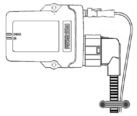
Mount the Device
Tip
Mount the device in such a way that it is not directly exposed to weather conditions, especially rain and direct sunlight as this may influence the ingress protection and thus lead to damage to the device, see also Mounting Orientation.
To mount the device, proceed as follows:
Mount the device directly with 2 socket-head screws (M5) inserted in the mounting holes on the sides and screwed to the mounting surface.
For detailed information on the distances between the holes, see Technical Drawings.
-
The recommended tightening torque for assembly is 2.2Nm +/- 0.3 Nm
-
The mounting is not suitable for hexagon head bolts.
-
An alternative fastening are M5 screws with a head diameter ≤ 12 mm and an internal drive.

-
Socket-head screw
DIN912 - M5 x 30 mm. The screw should have a length of25 mmplus the mounting plate thickness (up to 5 mmm). For tightening the enclosure, there is a hole on each side with a diameter of 5.5 mm. -
Lock washer
M5, di/D = 5.3/9 mm -
CANlink mobile
-
Mounting plate
-
Hexagon nut
DIN934 / ISO4032 - M5
Note
The mounting material is not included in the scope of delivery. Optionally, you can use the Mounting kit M5 housing GH120x (part number 141000017). The mounting set contains the following components:
- 2 socket-head screws
DIN912 - M5 x 30 mm - 4 lock washers
M5, di/D = 5.3/9 mm - 2 hexagon nuts
DIN934 / ISO4032 - M5
Provisioning and GoLive

Provisioning allows you to make a machine with a telematics unit installed available on the DataPortal. The machine will be visible and during the process you can assign a model and change the machine name, serial number and PIN/VIN.
GoLive is the automated activation of a communication unit (CU) after Provisioning. Once the CU has been activated, it is authorized to connect to the DataPlatform and transfer data.
- Login to the Proemion DataPortal.
- Login with your username and password.
- Provision the CANlink mobile to make it visible on your DataPortal account as described in the DataPortal User Manual > Provisioning.
- Use DataPortal > GoLive to activate the device and permit DataPortal communication.
Note
For the first time login, the initial password must be set. Please use the “Forgot password” function on DataPortal.
Enter the username which was provided along with the account setup confirmation email.
Another email with instructions on how to reset the password will be sent to your email address.
Note
Please note that the activation of the SIM card can take up to 24 hours in exceptional cases.
First Connection
The CANlink® mobile 10000 provides a local web server with a configuration web user interface (configuration web UI) allowing basic interface configurations.
To reach the device follow this steps:
- Unpack and connect the device to the power supply.
- Connect the device to your PC via Ethernet — simply plug the Ethernet cable into both.
- Open the web browser and type the default IP address:
192.168.82.1. -
A login window opens where you need to type in the credentials:
- The username is: admin.
- The initial password is provided on the Type Label of the device.
Note
Devices manufactured before August 1st, 2025, use the Ethernet MAC address as the initial password.
For more information go to Configuration Web UI in the device manual.
Check also the next chapter CODESYS Introduction.
Configure CODESYS IDE
Introduction
Proemion ships all the CANlink® mobile 10000 devices with support of CODESYS Development System.
CODESYS is a versatile software platform for developing and programming industrial automation applications, supporting IEC 61131-3 standard languages like Ladder Logic and Structured Text.
Widely used for PLCs and motion control systems, it offers tools for simulation, visualization, and communication protocols for various interfaces like CAN or Ethernet.
Clarification for customers migrating from CANlink® mobile 3600
CODESYS replaces the Proemion Configurator tool which will not be used in this product.
In order to work with CODESYS, proceed as follows:
- Install CODESYS, see Install CODESYS.
- Install dependencies, see Install dependencies.
- Activate license, see Activate CODESYS library.
Install CODESYS
Install CODESYS
Install the latest CODESYS IDE from https://store.codesys.com/de/codesys.html.
A CODESYS account is needed, you can create one or contact your CODESYS administrator.
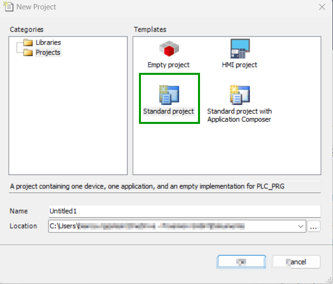
-
Create a new project by choosing "New Project" to start:
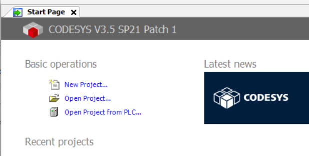
Figure 1: New project -
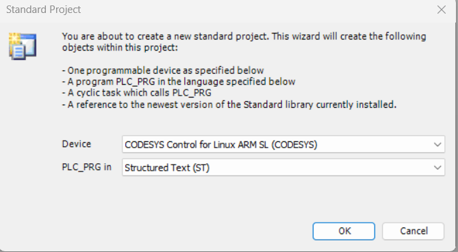
Choose a standard project to get the tree structure with relevant folders and features and confirm:
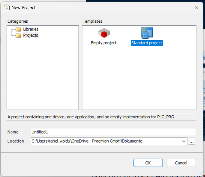
Figure 2: Select Standard Project 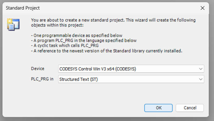
Figure 3: Confirm
Install Linux ARM Add-on
In order to work with CODESYS, you must install the CODESYS Control for Linux ARM SL dependency.
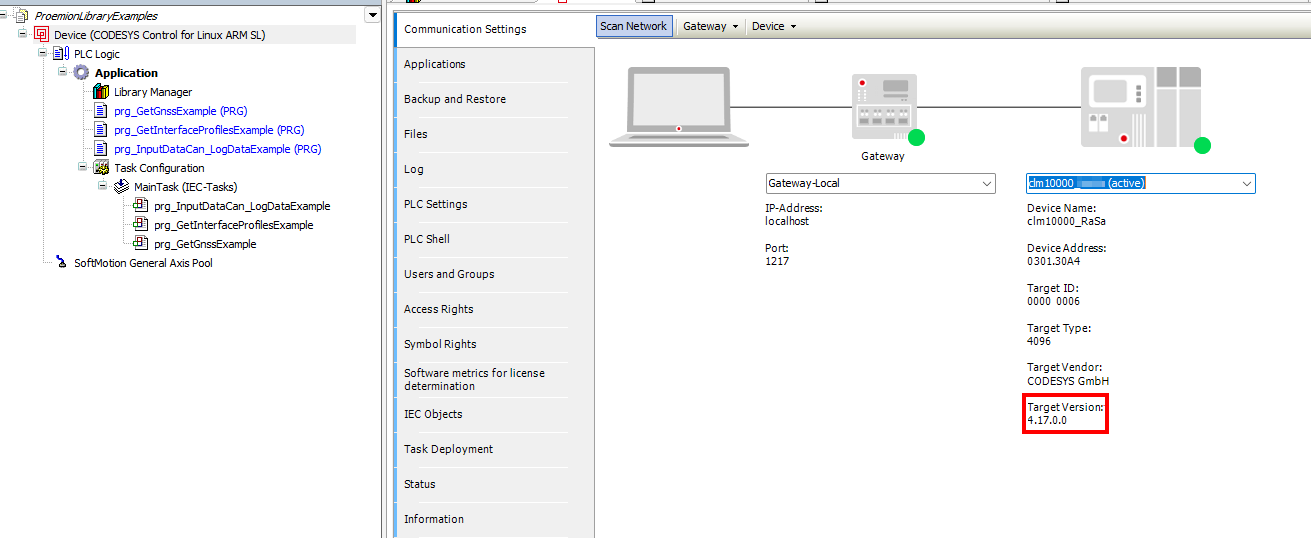
The specific version of the CODESYS Control for Linux ARM SL depends on the firmware version of the CANlink® mobile 10000.
The version running on the device must be the same as or newer than the one used in your CODESYS project.
Projects created with a newer version than the device supports will not run correctly.
To determine the correct version:
- Refer to the firmware release notes; view available versions under Firmware Management in the DataPortal
- You can also verify the version directly in CODESYS when connecting to the device (see screenshot below).
To install the dependency, proceed as follows:
- Start the CODESYS Development System.
-
Open the CODESYS Installer via Tools > CODESYS Installer:
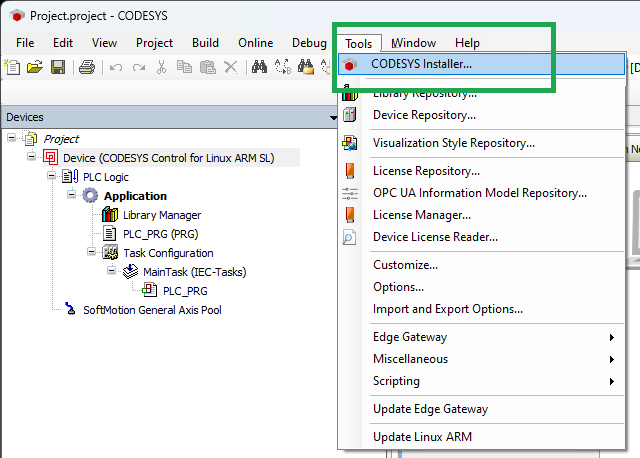
Figure 5: CODESYS Installer -
Search for CODESYS Control for Linux ARM SL and install the correct version.
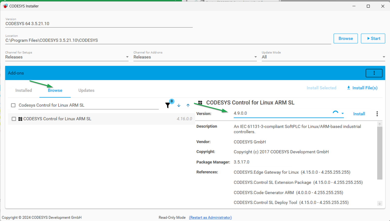
-
After successful installation, close the CODESYS Installer. You might need to close the CODESYS Development System application to complete the installation process.
- Restart the CODESYS Development System to apply the changes.
Install IIoT Libraries SL Add-on
The IIoT Libraries SL Add-on ensures compatibility with modern IIoT protocols and simplifies secure, standardized communication.
Starting with version 2.0.0 of the Proemion CANlink® mobile 10000 library, features like JSON handling and Web HTTPS communication are used as dependencies. These are provided by the IIoT Libraries SL Add-on, which is therefore mandatory for all projects using version 2.0.0 or higher.
To install the CODESYS IIoT Libraries SL dependency, proceed as follows:
- Start the CODESYS Development System.
-
Open the CODESYS Installer via Tools > CODESYS Installer:
Figure 6: CODESYS Installer -
Search for CODESYS IIoT Libraries SL and install the latest version.
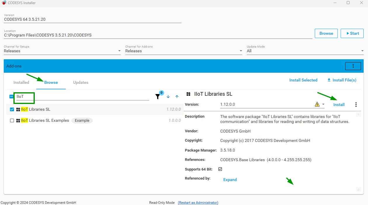
-
After successful installation, close the CODESYS Installer. You might need to close the CODESYS Development System application to complete the installation process.
- Restart the CODESYS Development System to apply the changes.
Add Proemion CANlink® mobile 10000 Library
The Proemion CANlink® mobile 10000 library for the CODESYS Development System is available in the Download Center. It also includes general descriptions and specific documentation for each feature.
Download and Install Library
You must install the library on your computer.
-
The file is available in the Download Center under:
01_Proemion_Devices > 09_CANlink mobile 10000 > 10_Other Software. Save it under a common path, e.g.CODESYS > Managed Libraries. -
In CODESYS, open the Library Repository window via Tools > Library Repository.
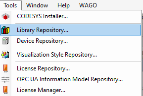
Figure 1: CODESYS - Library Manager -
Select Install. In the "Select Library" window, select the downloaded library. Older versions of the library might be installed under Miscellaneous. From version 2.1.0.0, it will be under Application.
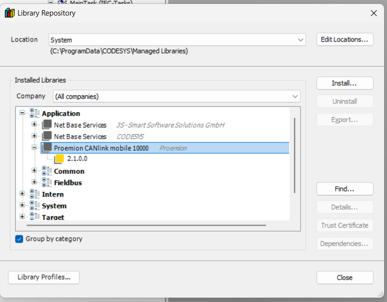
Figure 2: Library Download Path -
Close the window.
Use Library for Project
After downloading the library, you can add it to the CODESYS project.
-
In CODESYS, select the Library Manager window.
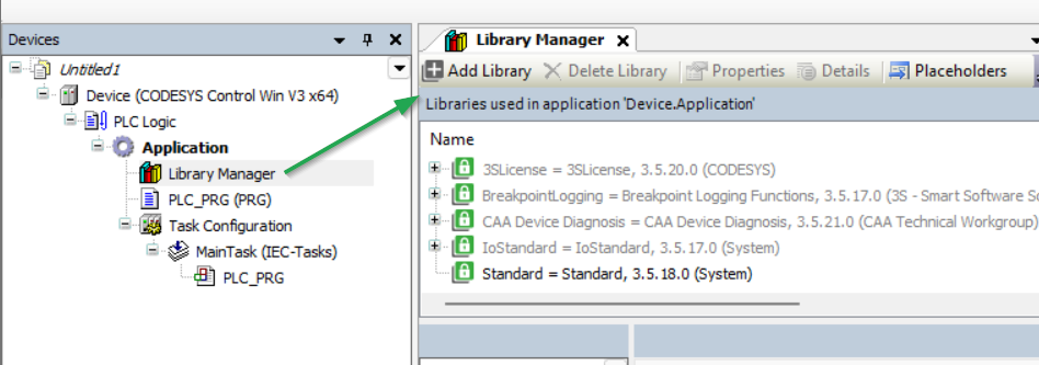
Figure 3: Open Library Manager -
Select the CLM10K library via Add Library. You have successfully added the CANlink® mobile 10000 library:
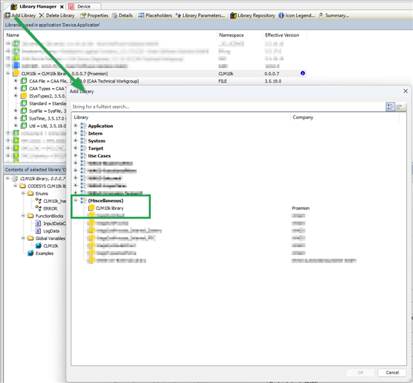
Figure 4: Library Manager
Library Documentation
Selecting the directory opens the documentation:
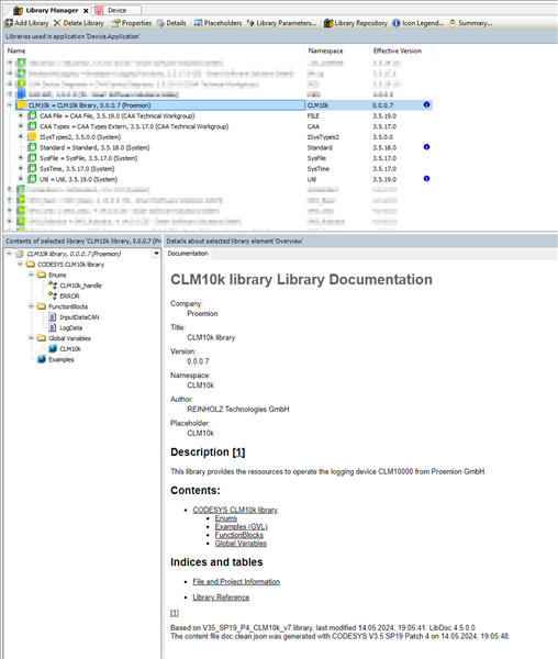
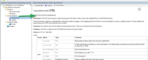
The directory CODESYS CANlink® mobile 10000 library > FunctionsBlocks includes documentation for each feature, e.g. "LogData" for CAN data logging to DataPlatform.
Activate CODESYS licenses
Without an activated CODESYS license the CODESYS application runs for 2 hours on the CANlink® mobile 10000. To restart the CODESYS application the user needs to restart the device e.g. by performing a power reset, see Main Plug Connector in the device manual.
The CANlink® mobile 10000 Variant CRT comes with two activated CODESYS licenses by default. For more details see also Available Models/Types in the CANlink® mobile device manual.
Activation
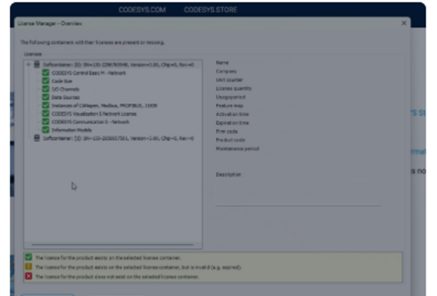
The activation of the CODESYS licenses is performed with the CODESYS Development System, an external tool maintained by the company CODESYS, see CODESYS Online Help. Refer to their documentation and consider the following CANlink® mobile 10000-specific steps in the CODESYS License Manager:
-
Open the License Manager:
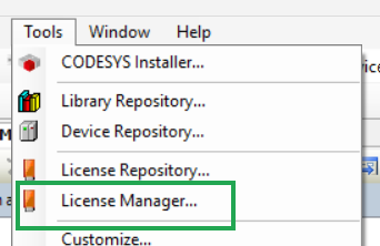
Figure 1: Open the License Manager -
Select Device in the Select Target window:
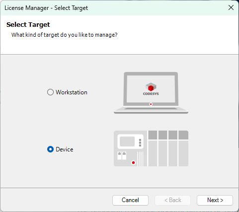
Figure 2: CODESYS Licence Manager - Select Target -
Select the network path to the device and click OK:
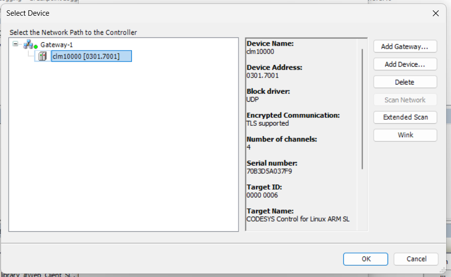
Figure 3: Select Device -
If no CODESYS user management is configured, you will be prompted to activate it now. You will then be asked to create a password which will be used to log in to the device:
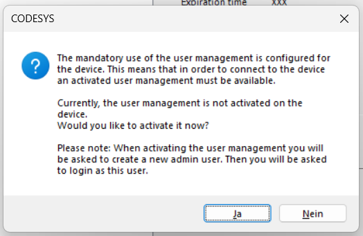
Figure 4: Create password dialog 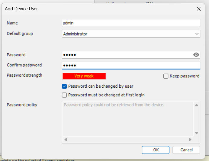
Figure 5: Add password CODESYS password handling
Save your CODESYS password immediately as it might be necessary to enter it several times.
You must securely store the configured CODESYS password.
Proemion does not have access to the CODESYS application without this password. If the password is lost, Proemion cannot access or analyze the application in support cases.
-
You might need to login again with the password:
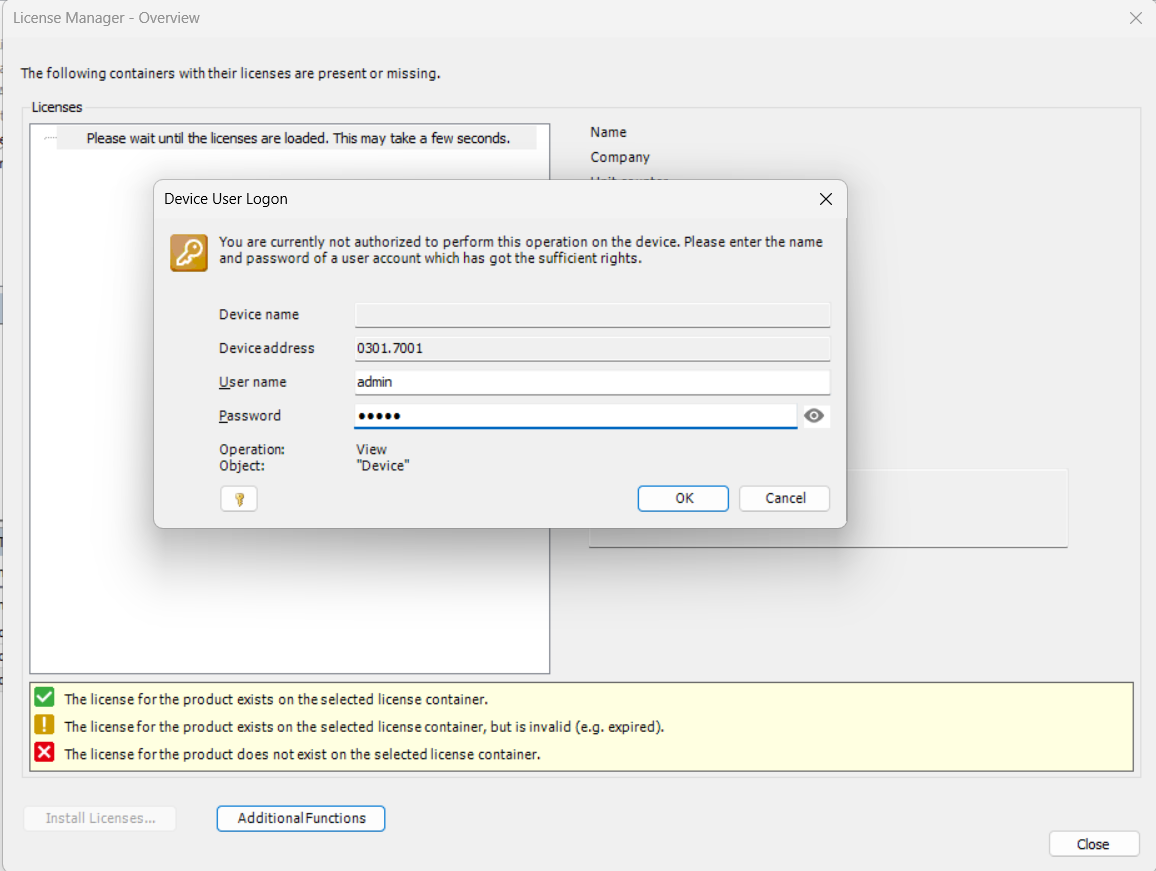
Figure 6: Device user logon -
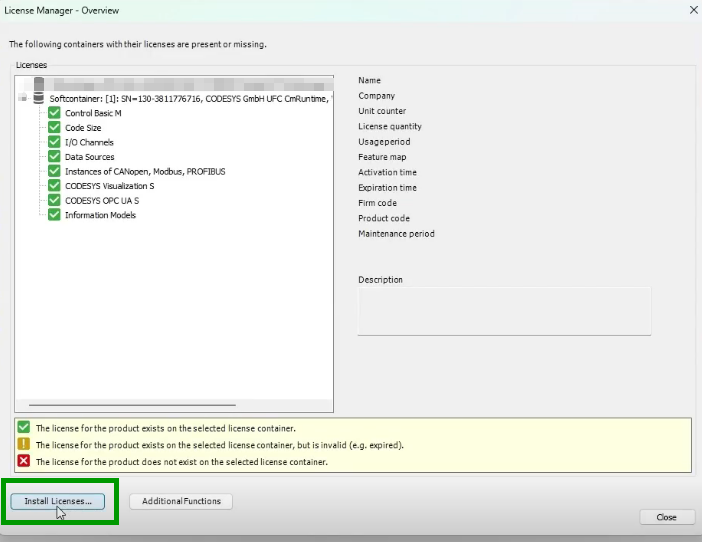
Select Install license at the bottom of the License Manager window:
-
Select Activate license in the Install licenses window:
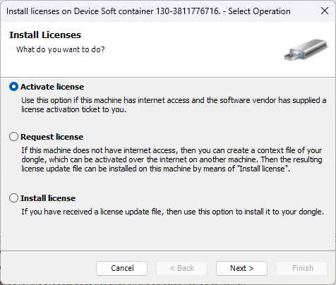
Figure 7: CODESYS Licence Manager - Activate license -
Enter the license information and click Next:
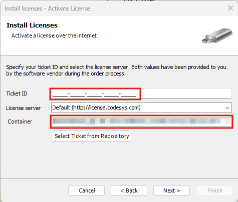
Figure 8: Enter license -
Select the licenses:
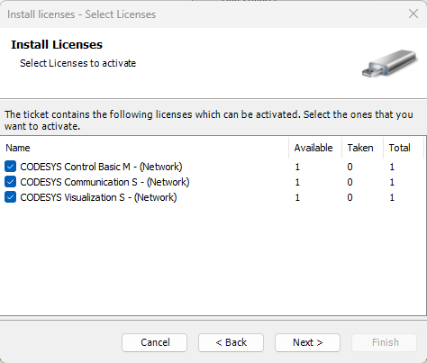
Figure 9: Select the license -
The selected licenses will be loaded in the License Manager.
CODESYS Device Description
CANlink® mobile 10000 Device Description in CODESYS
Starting with firmware version 3.3.0, the CANlink® mobile 10000 supports a CODESYS Device Description file, which defines how the device is represented in CODESYS and provides access to its inputs, outputs and internal sensors.
The file is preconfigured and works without user modification once added to a project.
However, you may need to manually install the required ExtensionAPI (CODESYS) library:
- The ExtensionAPI library is referenced by the IoDrvSocketUnix library.
- It is required to use the provided Device Description file in your application.
- Although the IoDrvSocketUnix library is automatically added when you include the Device Description file, the ExtensionAPI library may not be installed by default in your CODESYS Development System.
If the library is missing, the Development System will display an error.
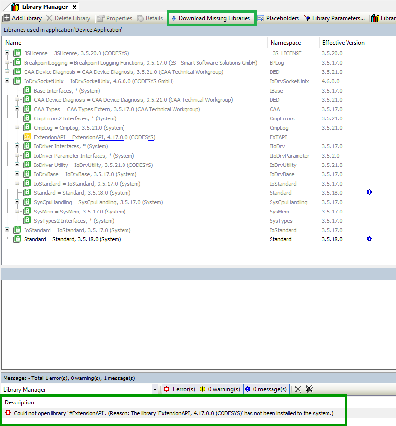
To resolve this:
- Open the Library Manager in CODESYS.
- Search for ExtensionAPI.
- Download and install the library if it is not already available.
Access signals
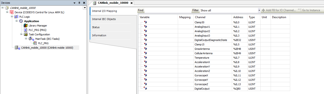
After adding the device to the project, the following explains where its signals can be found within CODESYS.
Add the device to your project and open the device tree. Signals are available via I/O Mapping or device variables (e.g., Clamp30, analog inputs, temperature).
Understand data representation and conversion
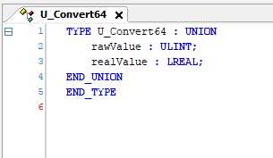
In the CODESYS environment, the ExtensionAPI uses ULINT as a universal container for 64-bit data.
Since LREAL (double precision floating-point) values are not directly supported in this context, measurement values are provided as ULINT and must be interpreted accordingly.
To access the original floating-point values, the 64-bit data is reinterpreted as LREAL.
In CODESYS, this is typically done using a UNION, which allows accessing the same memory as both ULINT and LREAL without modifying the underlying value.
This approach ensures that no data is lost, as the conversion is a bitwise reinterpretation of the same value.
Signals represented this way:
- Clamp30
- Clamp15
- Analog inputs
- Internal temperature
- Gyroscope values
- Accelerometer values
The following example shows how a value received from the device as ULINT is reinterpreted as LREAL using a UNION.
Example:
TYPE U_Convert64 : UNION
    rawValue : ULINT;
    realValue : LREAL;
END_UNION
END_TYPE
VAR
    converter : U_Convert64;
    result : LREAL;
END_VAR

converter.rawValue := InputValueFromDevice;
result := converter.realValue;
The screenshot below shows this approach in the CODESYS Development System.
A ULINT value is assigned to the UNION and accessed as LREAL without modifying the underlying data.
Check signal units
After reinterpretation, the signals correspond to the following physical units.
| Signal | Unit | Notes |
|---|---|---|
| Clamp30 | V | ULINT → LREAL |
| Clamp15 | V | ULINT → LREAL |
| Analog inputs | V | ULINT → LREAL |
| Internal temperature | °C | ULINT → LREAL |
| Gyroscope values | °/s | ULINT → LREAL |
| Accelerometer values | g | ULINT → LREAL |
| Digital output | bool | TRUE = outputs Clamp30 |
Interpret antenna status
The following values indicate the status of the cellular and GNSS antennas.
| Value | Meaning |
|---|---|
| 0 | Unknown |
| 1 | Not connected |
| 2 | Connected |
| 3 | Short circuit |
These values can be mapped to an enumeration for improved readability.
CODESYS example:
TYPE AntennaState :
(
    Unknown        := 0,
    NotConnected   := 1,
    Connected      := 2,
    ShortCircuit   := 3
) USINT;
END_TYPE
Use the digital output
The digital output can be controlled via a boolean value:
TRUEenables the output and applies the Clamp30 supply voltageFALSEdisables the output
The diagnostic state provides additional information about the output condition.
| Value | Meaning |
|---|---|
| 0 | No problems |
| 1 | Problem detected |
In case of an error, the output is automatically disabled and temporarily blocked to prevent overheating.
These diagnostic values can also be represented using an enumeration.
CODESYS example:
TYPE DOUTDiagnosticState :
(
    NoProblems        := 0,
    ProblemsDetected  := 1
) USINT;
END_TYPE
CODESYS Examples
Introduction
Before starting with the examples, make sure you have installed CODESYS, added all required dependencies, and activated the library license as described here.
This initial setup installs all necessary dependencies required for the examples to run correctly.
The following examples provide a guided introduction to logging data with CODESYS and the CANlink® mobile 10000:
These examples demonstrate the basic setup and usage of the CANlink® mobile 10000 with CODESYS.
In addition, a collection of CODESYS example projects is available in the GitHub repository. The repository provides CODESYS project archives for different use cases (e.g., J1939 diagnostic message handling such as DM1 or extended logging scenarios).
Log Data using the CANlink® mobile 10000 Library
First you have to set up a new CODESYS project for the CANlink® mobile 10000.
To do so, follow these steps.
Create a new CODESYS Project
Open the CODESYS IDE, create a new project via File → New Project → Standard Project and choose a Name and Location for your project.
Select Device and Programming Language
Select Device and PLC_PRG in.
- Select Device: CODESYS Control for Linux ARM SL
- Choose programming language for PLC_PRG: Structured Text (ST)
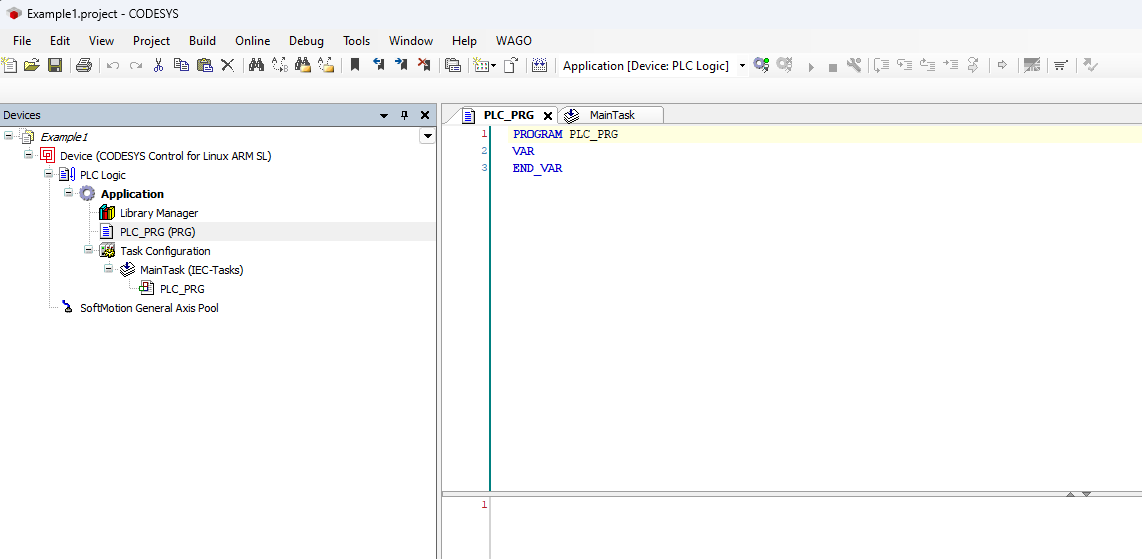
If the device CODESYS Control for Linux ARM SL is not available, it may not be installed. Read Install CODESYS dependencies for installation instructions. An empty project similar to the following screenshot should be created.
Enable CODESYS Runtime on the CANlink® mobile 10000
Before adding the CANlink® mobile 10000 library or programming, ensure the CODESYS Runtime is enabled on the device:
- Open a web browser and access the device’s IP address.
- Log in to the web interface.
- Navigate to Advanced Settings > CODESYS Settings.
- Enable the option Enable CODESYS Runtime.
- Save the settings (restart the device if required).
Once enabled, the device is ready for CODESYS connection and library integration.
Add the CANlink® mobile 10000 CODESYS Library
Add the CANlink® mobile 10000 CODESYS library to your project.
1. Open the Library Manager in the Devices tree on the left side of the CODESYS IDE, expand the Application node under your device and double-click on Library Manager.
2. Click the + Add library button in the Library Manager toolbar at the top of the screen. This opens the Add Library window, allowing you to search and add new libraries to your project.
3. Search and select the CANlink® mobile 10000 library.
4. Click OK in the bottom-right corner of the window to confirm your changes.
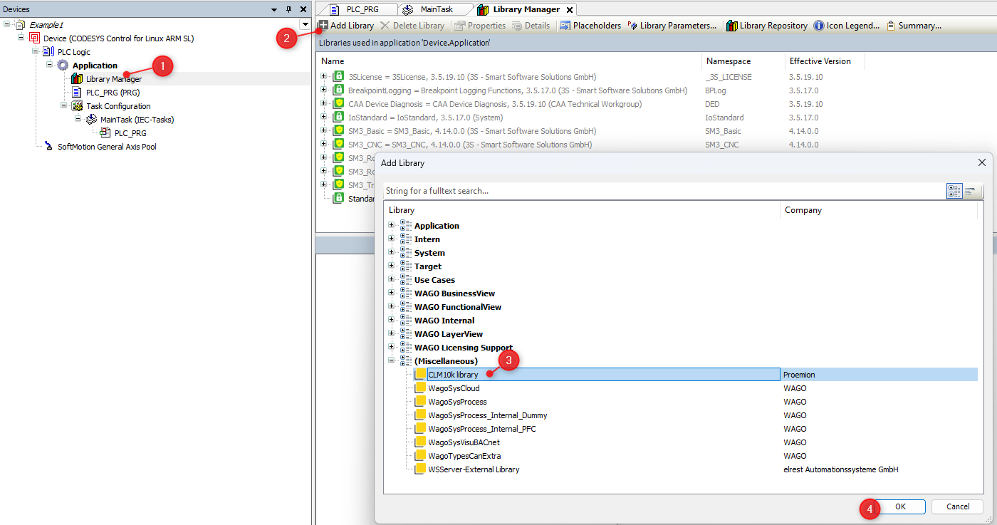 If you can not find the CANlink® mobile 10000 library, it may be not installed.
Read Add Proemion CANlink® mobile 10000 Library for installation instructions.
If you can not find the CANlink® mobile 10000 library, it may be not installed.
Read Add Proemion CANlink® mobile 10000 Library for installation instructions.
Example
The following example provides a detailed step-by-step instruction
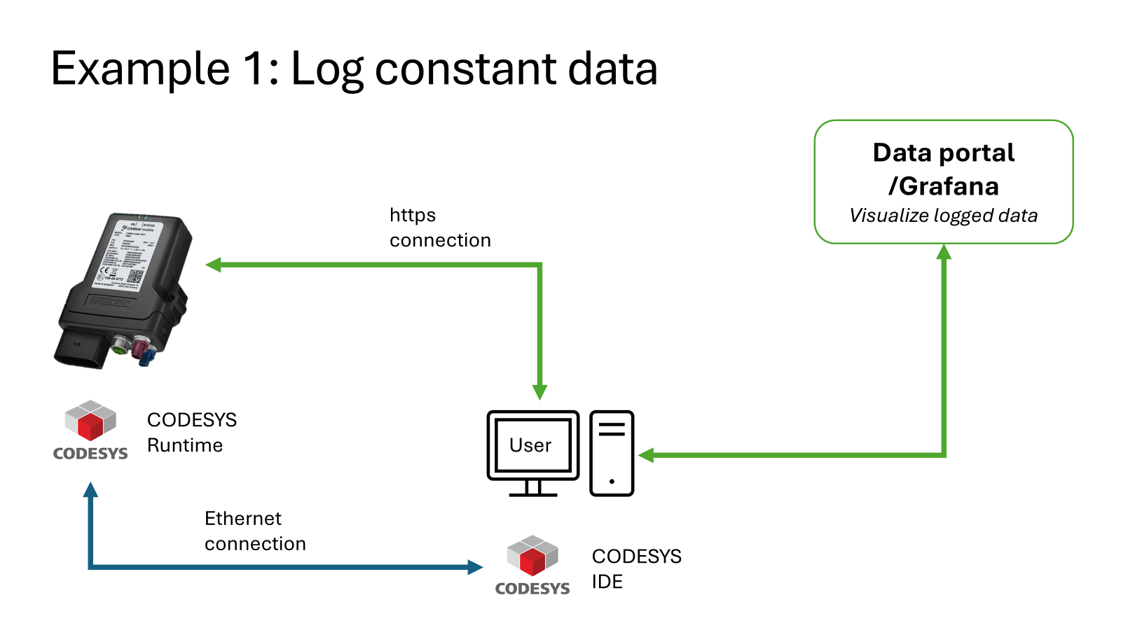
The diagram below illustrates how the CANlink® mobile 10000 logs constant data and transmits it over HTTPS to the DataPortal for visualization, while the user interacts with the system through the CODESYS IDE over an Ethernet connection.
-
The library comes with an example embedded into the documentation. The following Screenshot shows you how to find it. Copy and paste it into your main program PLC_PRG. The code may vary slightly depending on the version of the CANlink® mobile 10000 library you are using.
- 1: Open the CANlink® mobile 10000 library contents in the Library Manager, under the list of included libraries. Click on CANlink® mobile 10000
Proemion to select it. This displays the contents and structure of the library in the bottom-left panel. - 2: To open the example code, navigate to CANlink® mobile 10000 library > Global Variables > Example and click on Examples.
This opens the GVL (Global Variable List) Examples, which contains predefined test variables, logging structures, and example logic for input and output configuration using the CANlink® mobile 10000 library.
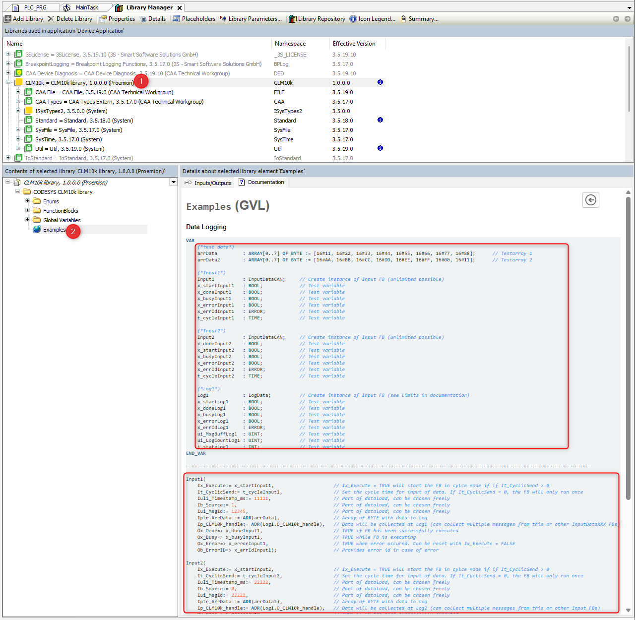
- 1: Open the CANlink® mobile 10000 library contents in the Library Manager, under the list of included libraries. Click on CANlink® mobile 10000
-
Navigate to Build > Generate Code in the top menu to compile the project. Ensure that no errors or warnings appear in the message window at the bottom of the IDE.
-
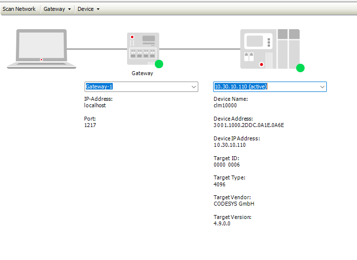
Connect to the device. You can use the Scan Network to locate your CANlink® mobile 10000 device.
- 1: Select the device. In the Devices tree on the left side of the CODESYS IDE, click on your target device entry, e.g. Device (CODESYS Control for Linux ARM SL), to select it and enable access to communication and configuration options.
- 2: Open Communication Settings. With the device selected, open the Device tab at the top of the IDE and click on Communication Settings in the left-hand menu to open the network configuration view for connecting to your target hardware.
- 3: Click on Scan Network to find your device. If you can not find it you can also enter the IP address; in the Communication Settings window, enter the IP address of your CANlink® mobile 10000 device (e.g.
10.30.10.110) into the input field on the right, press Enter to scan and connect, and if prompted, enter the device User name and Password in the login dialog to authorize access. The User name and Password must be set the first time you connect via CODESYS. For further information read also the CODESYS Project Protection Documentation.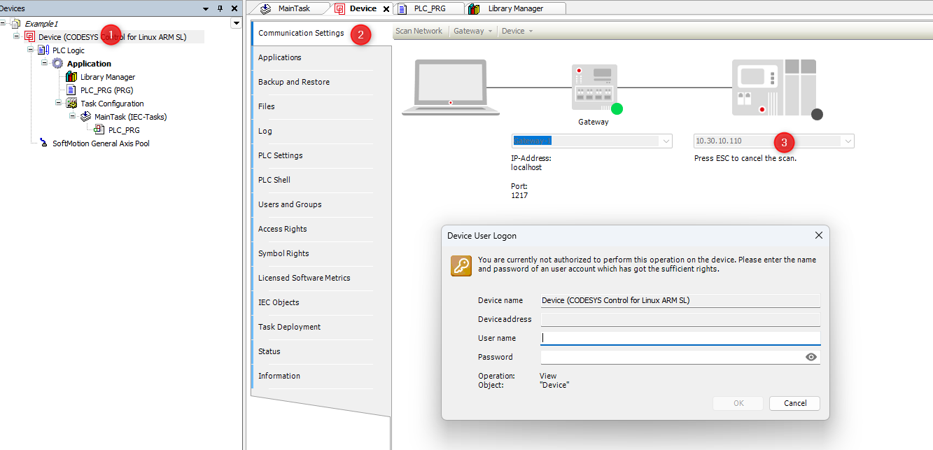 After logging in to the CANlink® mobile 10000 device, the following screen confirms that the connection between your CODESYS IDE and the device has been successfully established.
-
Download the compiled project to the device.

Figure 5: Download application -
Start the application from within CODESYS IDE.

Figure 6: Start application Check that your variables are correctly initialized. Your variables should appear similar to the following screenshot.
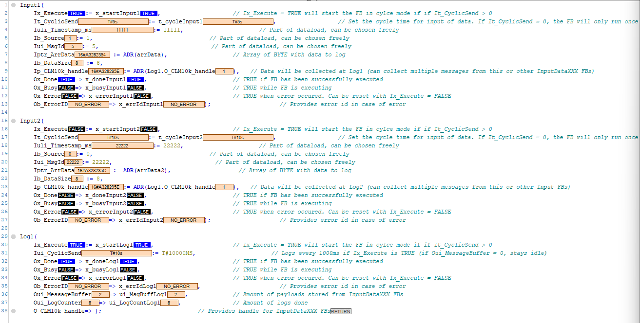
Figure 7: Example variables -
Enter the IP address of your CANlink® mobile 10000 into a web browser to access its web interface. You should access the following page.
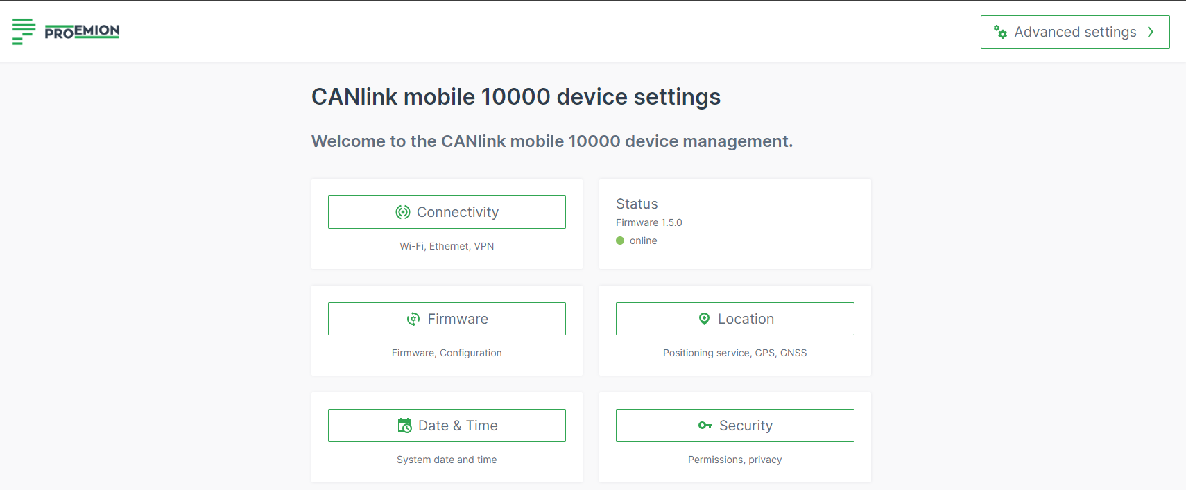
Figure 8: Web interface CANlink® mobile 10000 -
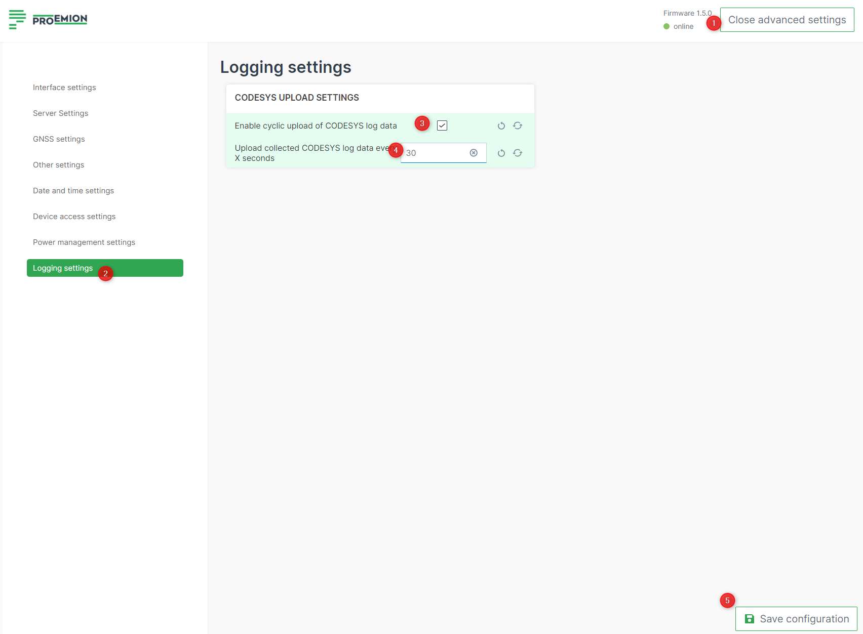
Adjust CODESYS UPLOAD SETTINGS to upload
.clffiles every 30 seconds.- 1: Navigate to Advanced Settings > Logging settings.
- 2: Open the Logging settings.
- 3: Enable cyclic upload of CODESYS log data: activate checkbox.
- 4: Upload collected CODESYS log data every X seconds: type 30.
Set up and connect to a J1939 simulation environment
First you have to set up a new CODESYS project for the CANlink® mobile 10000.
To do so, follow these steps.
Create a new CODESYS Project
Open the CODESYS IDE, create a new project via File → New Project → Standard Project and choose a Name and Location for your project.
Select Device and Programming Language
Select Device and PLC_PRG in.
- Select Device: CODESYS Control for Linux ARM SL
- Choose programming language for PLC_PRG: Structured Text (ST)
If the device CODESYS Control for Linux ARM SL is not available, it may not be installed. Read Install CODESYS dependencies for installation instructions. An empty project similar to the following screenshot should be created.
Enable CODESYS Runtime on the CANlink® mobile 10000
Before adding the CANlink® mobile 10000 library or programming, ensure the CODESYS Runtime is enabled on the device:
- Open a web browser and access the device’s IP address.
- Log in to the web interface.
- Navigate to Advanced Settings > CODESYS Settings.
- Enable the option Enable CODESYS Runtime.
- Save the settings (restart the device if required).
Once enabled, the device is ready for CODESYS connection and library integration.
Add the CANlink® mobile 10000 CODESYS Library
Add the CANlink® mobile 10000 CODESYS library to your project.
1. Open the Library Manager in the Devices tree on the left side of the CODESYS IDE, expand the Application node under your device and double-click on Library Manager.
2. Click the + Add library button in the Library Manager toolbar at the top of the screen. This opens the Add Library window, allowing you to search and add new libraries to your project.
3. Search and select the CANlink® mobile 10000 library.
4. Click OK in the bottom-right corner of the window to confirm your changes.
If you can not find the CANlink® mobile 10000 library, it may be not installed.
Read Add Proemion CANlink® mobile 10000 Library for installation instructions.
Example
The following example provides a detailed step-by-step instruction
This documentation describes how to test the J1939 setup by connecting the CAN interface to a simulated J1939 network using a WAGO PLC. However, the setup will also work with any device that generates J1939 messages.
You can import this example — along with all required dependencies — using the following project archive.
-
Add J1939_ECU. Navigate to
CANBus → J1939_Managerin the CODESYS device tree, then add a new J1939_ECU instance to configure and manage the J1939 communication for the ECU. Watch the video for a step-by-step guide.
-
Configure the CAN Interface/Network and Baud Rate in the CAN Bus – General tab.
-
Download the J1939 database here and install it. Watch the video for a step-by-step guide.
-
Add the relevant Tx signals to the J1939 ECU. You will see the available PGNs and SPNs from your database, along with the corresponding conversion methods for each signal. Watch the video for a step-by-step guide.
-
Connect the CAN interface to the appropriate network. In the following example, a WAGO PLC is used to simulate the J1939 message.
You can download the sample here. -
Download the project to the target device. After deployment, you can map the incoming data to your local variables as usual. Watch the video for a step-by-step guide.
-
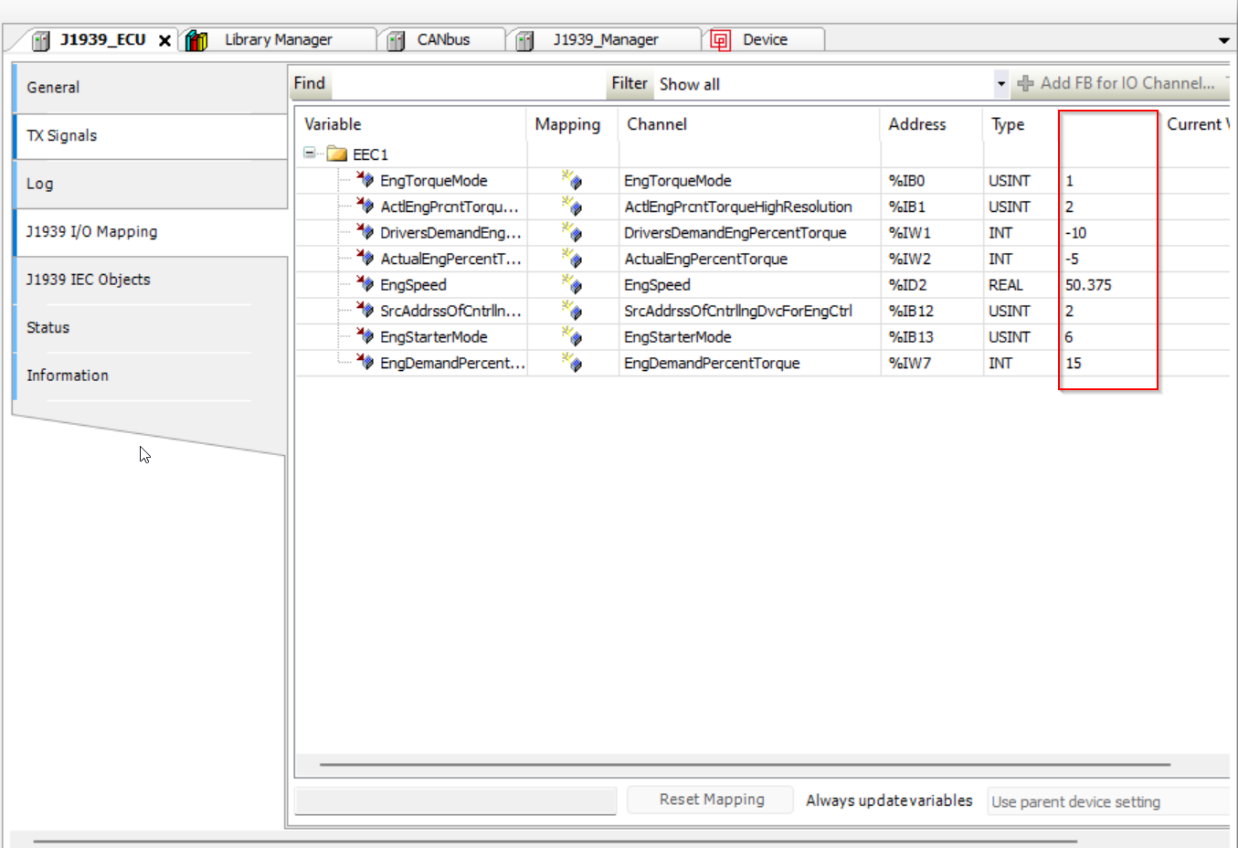
Go offline first, then enable Always Update Variables under
Device → PLC Settingsto ensure values are refreshed even if not used in the program. By default, variable values are only refreshed if used in the program.
The values should be updated here:
Service and Support
The latest versions of the drivers, software, firmware, and documentation are available at Document Library.
Do you need help or want to report a bug?
Visit Proemion for more information, or raise a ticket via Support.
Firmware Updates and Support
To ensure the best performance and security of your devices, we strongly recommend always installing the latest firmware provided by Proemion.
Please note:
We do not provide technical support for issues caused by outdated firmware.
Errors resulting from outdated firmware are considered non-qualified errors and are not covered by warranty or support.
Regular firmware updates are essential to maintaining the functionality of your devices.
If you need assistance with the update process, please contact our Service and Support.
For more information on the Firmware Update, check the device manual of your device at the Document Library.