Set up and connect to a J1939 simulation environment
First you have to set up a new CODESYS project for the CANlink® mobile 10000.
To do so, follow these steps.
Create a new CODESYS Project
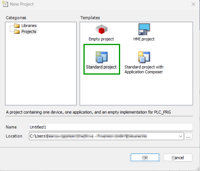
Open the CODESYS IDE, create a new project via File → New Project → Standard Project and choose a Name and Location for your project.
Select Device and Programming Language
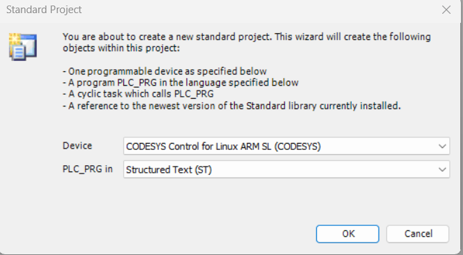
Select Device and PLC_PRG in.
- Select Device: CODESYS Control for Linux ARM SL
- Choose programming language for PLC_PRG: Structured Text (ST)
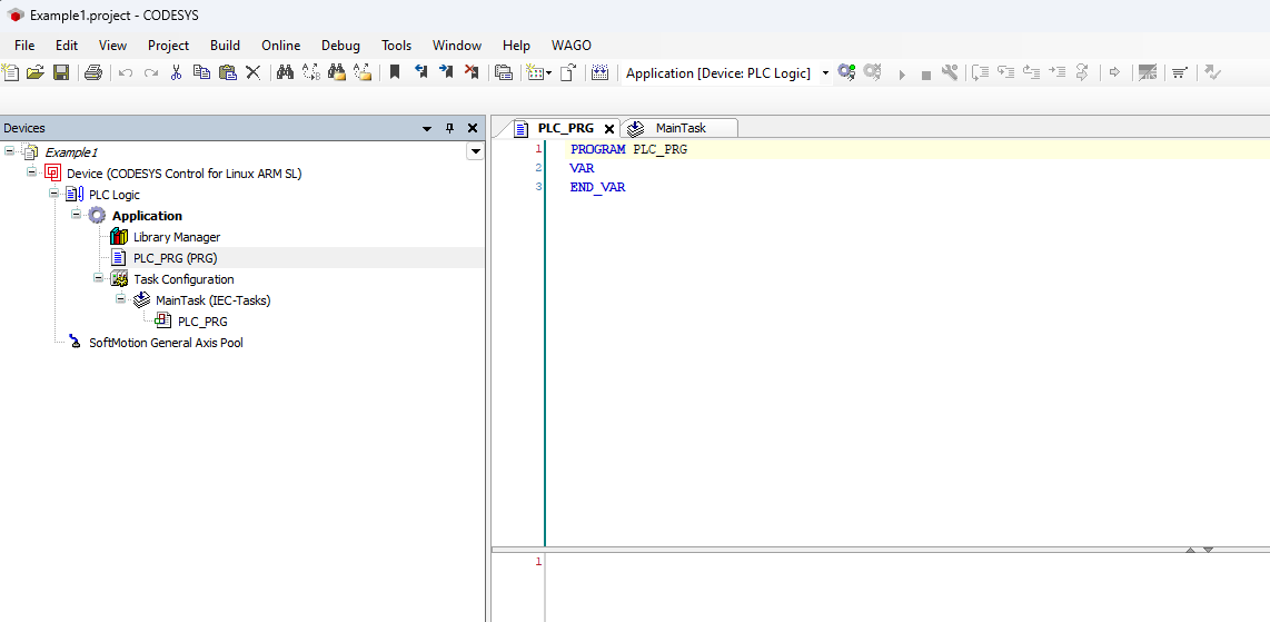
If the device CODESYS Control for Linux ARM SL is not available, it may not be installed. Read Install CODESYS dependencies for installation instructions. An empty project similar to the following screenshot should be created.
Enable CODESYS Runtime on the CANlink® mobile 10000
Before adding the CANlink® mobile 10000 library or programming, ensure the CODESYS Runtime is enabled on the device:
- Open a web browser and access the device’s IP address.
- Log in to the web interface.
- Navigate to Advanced Settings > CODESYS Settings.
- Enable the option Enable CODESYS Runtime.
- Save the settings (restart the device if required).
Once enabled, the device is ready for CODESYS connection and library integration.
Add the CANlink® mobile 10000 CODESYS Library
Add the CANlink® mobile 10000 CODESYS library to your project.
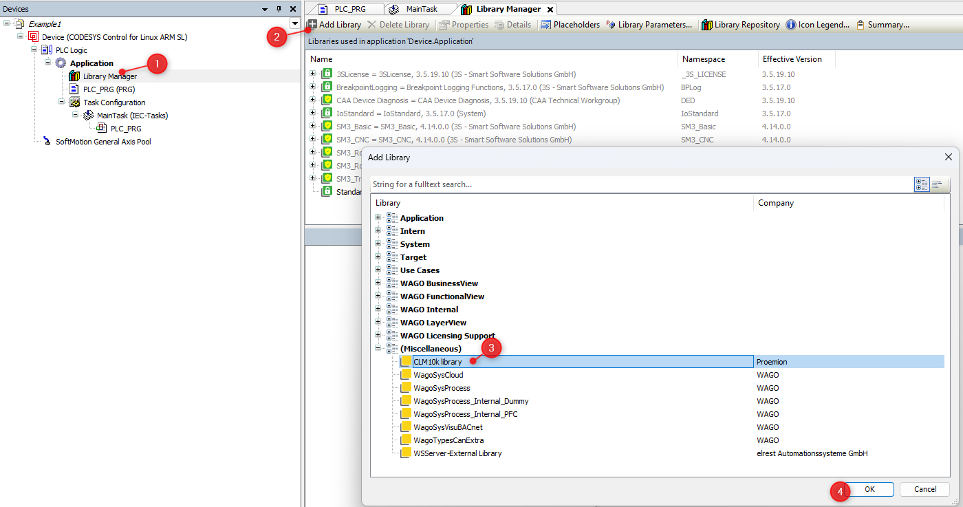
1. Open the Library Manager in the Devices tree on the left side of the CODESYS IDE, expand the Application node under your device and double-click on Library Manager.
2. Click the + Add library button in the Library Manager toolbar at the top of the screen. This opens the Add Library window, allowing you to search and add new libraries to your project.
3. Search and select the CANlink® mobile 10000 library.
4. Click OK in the bottom-right corner of the window to confirm your changes.
 If you can not find the CANlink® mobile 10000 library, it may be not installed.
Read Add Proemion CANlink® mobile 10000 Library for installation instructions.
If you can not find the CANlink® mobile 10000 library, it may be not installed.
Read Add Proemion CANlink® mobile 10000 Library for installation instructions.
Example
The following example provides a detailed step-by-step instruction
This documentation describes how to test the J1939 setup by connecting the CAN interface to a simulated J1939 network using a WAGO PLC. However, the setup will also work with any device that generates J1939 messages.
You can import this example — along with all required dependencies — using the following project archive.
-
Add J1939_ECU. Navigate to
CANBus → J1939_Managerin the CODESYS device tree, then add a new J1939_ECU instance to configure and manage the J1939 communication for the ECU. Watch the video for a step-by-step guide.
-
Configure the CAN Interface/Network and Baud Rate in the CAN Bus – General tab.
-
Download the J1939 database here and install it. Watch the video for a step-by-step guide.
-
Add the relevant Tx signals to the J1939 ECU. You will see the available PGNs and SPNs from your database, along with the corresponding conversion methods for each signal. Watch the video for a step-by-step guide.
-
Connect the CAN interface to the appropriate network. In the following example, a WAGO PLC is used to simulate the J1939 message.
You can download the sample here. -
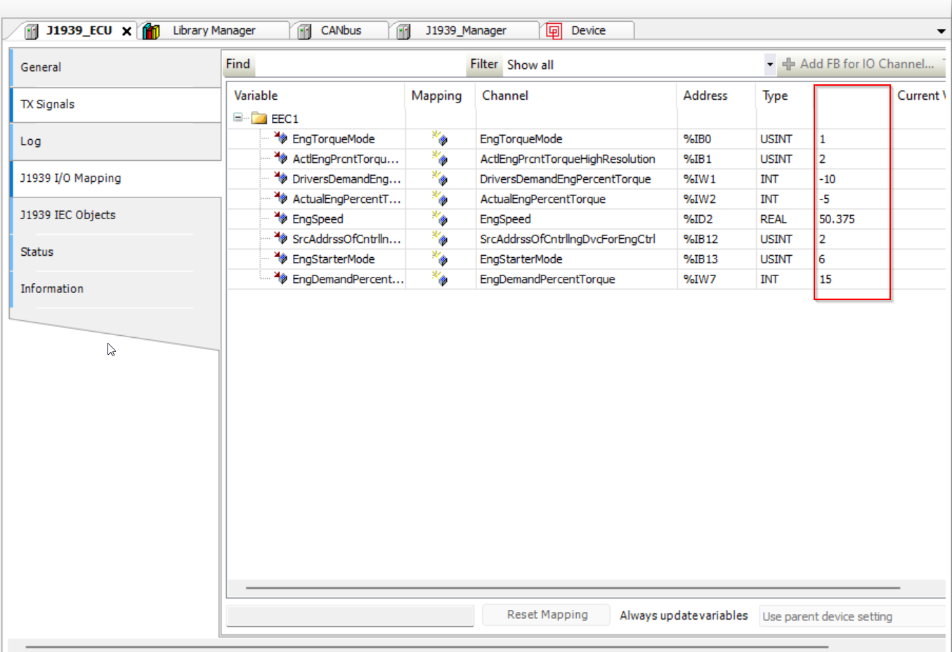
Download the project to the target device. After deployment, you can map the incoming data to your local variables as usual. Watch the video for a step-by-step guide.
-
Go offline first, then enable Always Update Variables under
Device → PLC Settingsto ensure values are refreshed even if not used in the program. By default, variable values are only refreshed if used in the program.
The values should be updated here: