Connectors
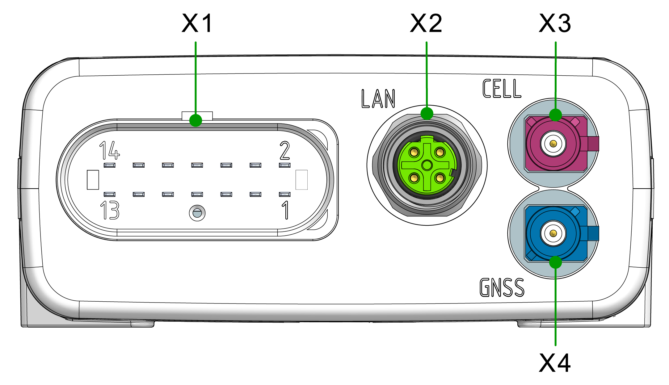
The device is equipped with the following connectors:
- X1 - main plug connector
- X2 - Ethernet, LAN
- X3 - cellular antenna connector
- X4 - GNSS antenna connector
Note
Mating Cycles According to the manufacturer's information, the connectors are equipped for the following minimum number of mating cycles:
- Main plug connector: 10 cycles
- Fakra plug: 100 cycles
- Cellular Antenna Port: 100 cycles
- Ethernet connector: 100 cycles
If the minimum number of mating cycles is exceeded, individual parameters could lie outside those in the specification; meaning, the mating cycles can be carried out without quality problems at least for the minimum numbers of mating cycles.
The basic function of the connectors remains intact.
Please be aware that the process of the CANlink mobile system integration is not designed for a high number of mating cycles.
Ideally the device is configured with an adapter cable from the Launch Kit in the first instance and in the second step installed and cabled within the machine.
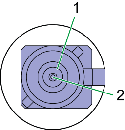
X1 - Main Plug Connector
Use the main plug connector to connect the device to the CAN bus and supply it with power. The I/O signals are integrated in the plug connector.
Note
The main plug connector contains a reset button. The Reset button is used to reset and thereby reboots the device, see Reset Device.
Note
The pin assignment shown here can vary depending on the type.
Note
The analog inputs operate in a range of 0 VDC to 15 VDC.
Optionally, you can use the input as a digital input with a maximum voltage of 36 VDC.
The digital output switches to supply voltage on terminal 30 and can only take a maximum load of 500 mA.
Provide an external safeguard if this limit is not ensured by the external terminal 30 power supply.
Input terminal 15 detects "high" from a voltage of 5.5 V and "low" below a voltage of 2.3 V.
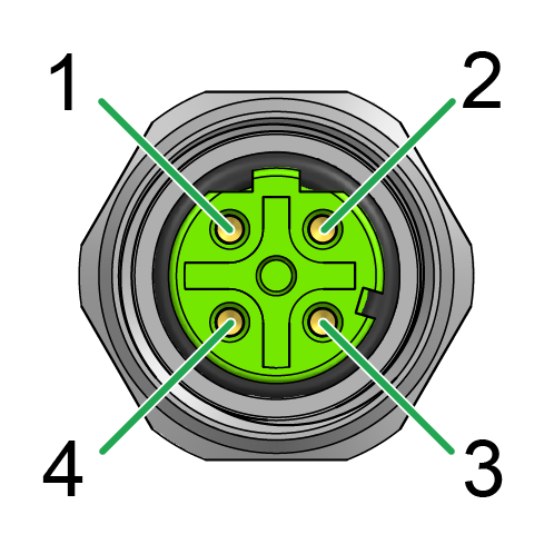
Pin assignment
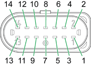
| Pin | Designation | Description |
|---|---|---|
| 1 | Terminal 30 / VCC | Power supply |
| 2 | CAN3-Low | CAN, bidirectional |
| 3 | Terminal 31 / ground | Power supply |
| 4 | Analog input 1 | I/O input |
| 5 | Analog input 2 | I/O input |
| 6 | Analog input 3 | I/O input |
| 7 | Digital output | I/O output |
| 8 | Terminal 15 | Input (ignition signal) |
| 9 | CAN3-High | CAN, bidirectional |
| 10 | Terminal 31 / ground | Power supply |
| 11 | CAN2-High | CAN, bidirectional |
| 12 | CAN2-Low | CAN, bidirectional |
| 13 | CAN1-High | CAN, bidirectional |
| 14 | CAN1-Low | CAN, bidirectional |
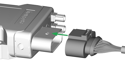
Connect main plug connector
Carefully connect the cable with the main plug connector.
The engagement force of the connector should be up to 86.0N.
When connecting the plug, there must be a clear audible click. Then the lock is correctly engaged.
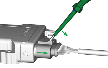
Disconnect main plug connector
To unplug the connection, slightly push the connector housing.
Then actuate the locking arm.
When the clicking is detached, the housing can be taken off.
In case there is no space to disconnect the plug as described, you can use an appropriate flat-blade screwdriver to release the lock (min. 5 mm).
Insert the screwdriver into the tab from above, then gently lever it down and back. At the same time, pull the plug slightly backwards by hand. If you can hear a click, the lock has been released and the connector can be removed.
Note
Risk of property damage
Leakage and contamination due to an increased number of mating cycles and improper disconnecting of the main plug connector.
- Make sure the device is switched off during installation.
- Do not forcibly lever the main plug connector off the device connector.
- Refer to the handling manual from the manufacturer at Automotive Connectors/DeyTrade Connecting - Handling Manual FEP Sealed Connectors.
X2 - Ethernet, LAN
Use the LAN connector to connect the device to a local area network and transmit data directly via the Ethernet connection.
The LAN connector is a standard M12 D-coded threaded connector. The recommended tightening torque is 0.6 Nm ±10%.
Pin assignment
See the following overview for the pin assignment of the Ethernet connector:
| Pin | Designation | Description |
|---|---|---|
| 1 | TxD+ | Transmit (output) |
| 2 | RxD+ | Receive (input) |
| 3 | TxD- | Transmit (output) |
| 4 | RxD- | Receive (input) |
| Metal thread | Shield | Earth connection |
Note
Connect Ethernet with mating connector IP6K7 and torque 0.6 Nm ±10%.
Note
The Ethernet-SHIELD must be connected to EARTH. This is normally done by use of a shielded cable with the Shield connected to an Ethernet-Switch with Earth-Connection.
Not doing so will result in regulatory non-compliance of the device and possibly failure of the Ethernet connection.
X3 - Cellular Antenna Connector
The cellular antenna connector is used to connect the device to an antenna to receive cellular signals.
Use only matching FAKRA mating connectors (C-coded for GNSS, D-coded for cellular) to maintain the device's IP protection class and electrical safety.
Pin assignment
See the following overview for the pin assignment:
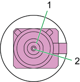
| Pin | Designation | Description |
|---|---|---|
| 1 | Ground | Signal ground /shielding |
| 2 | Signal | Cellular signal |
Note
Do not short-circuit the connector with Terminal 30 voltage.
This may damage the device.
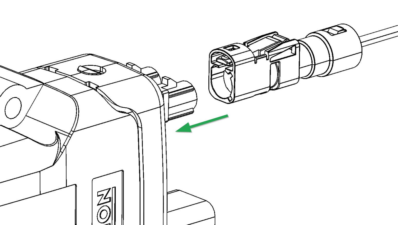
Connect antenna cable
Carefully connect the antenna cable with the coded antenna connector. Make sure that the coding within the socket is matching the coding of the connector. When connecting the plug, there must be a clear audible click. Then the lock is correctly engaged.
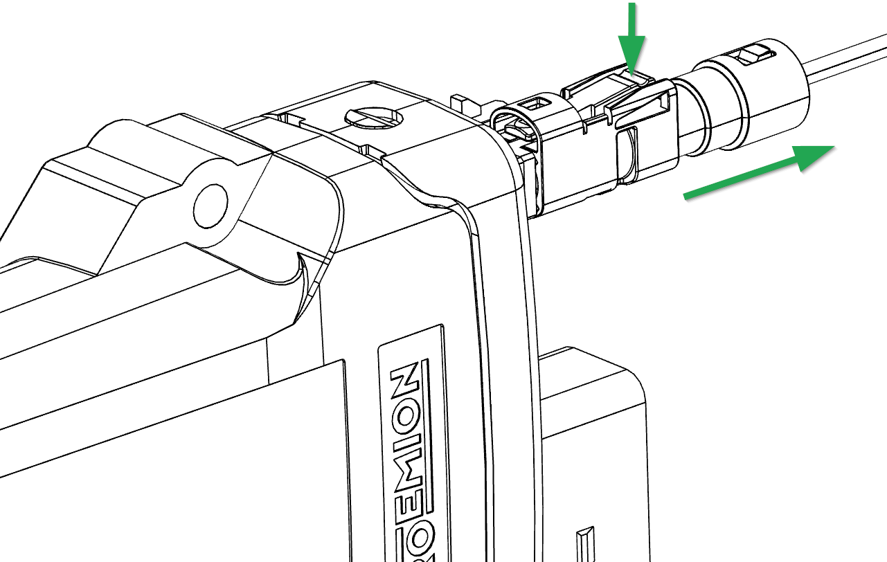
Disconnect antenna cable
Use your finger to release the lock by gently levering it down. At the same time, pull the plug slightly backwards by hand.
X4 - GNSS Antenna Connector
The GNSS antenna connector is used to connect the device to an active antenna to receive signals from GNSS satellites.
Use only matching FAKRA mating connectors (C-coded for GNSS, D-coded for cellular) to maintain the device's IP protection class and electrical safety.
Pin assignment
See the following overview for the pin assignment:
| Pin | Designation | Description |
|---|---|---|
| 1 | Ground | Signal ground /shielding |
| 2 | Signal | GNSS signal / supply voltage 3.3 V |
Note
Do not short-circuit the connector with Terminal 30 voltage.
This may damage the device.
For device Variants with dual-band GNSS support, use a compatible active GNSS antenna.
Using an incompatible antenna may reduce positioning performance.
For connecting and disconnecting the antenna, refer to Connect antenna cable and Disconnect antenna cable.