CANlink mobile 3700 Device Manual - PRELIMINARY
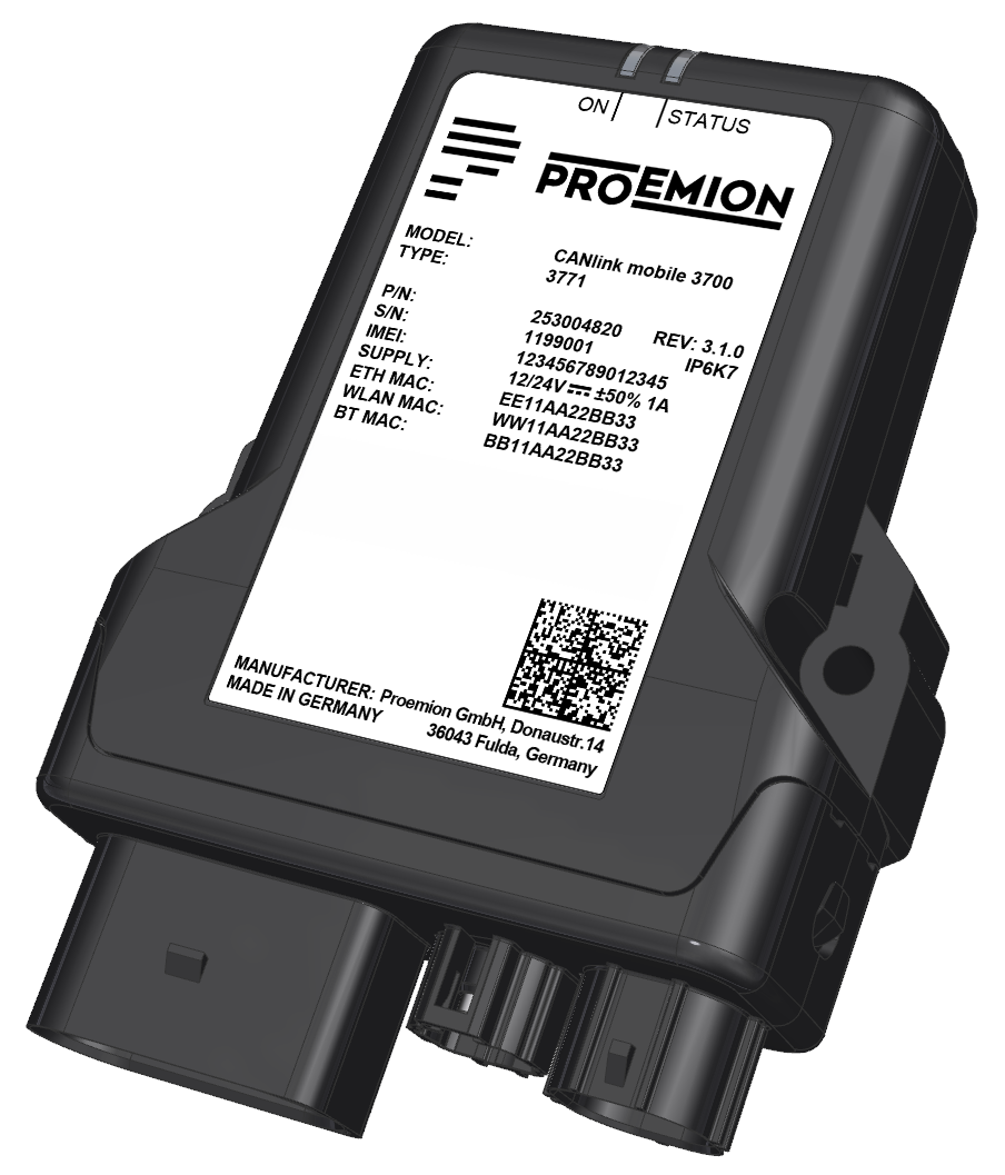
Preamble
Preamble
In the following chapter you find general information on the company and on the device manual.
Legal Notice
All brands and trademarks named in this document and possibly protected by third-party rights are subject without limitation to the terms of the valid trademark law and intellectual property rights of their respective registered owner.
You can find a list of the free-source and open-source software as well as copyright notes, license texts and, if applicable, the relevant source code on our website under the link: Free & Open Source Software Observe all local and regional laws and provisions as well as the safety instructions contained in this document.
Contact
Proemion GmbH
Donaustr. 14 36043 Fulda, Germany
Phone: +49 661 9490-0
Fax: +49 661 9490-111
info@proemion.com
Proemion Corp.
US Subsidiary 241 Taylor St., Suite 301
Dayton, Ohio 45402, USA
Phone: +1 937 558 2211
Fax: +1 937 641 8787
info-dayton@proemion.com
Proemion Ltd.
373 Gangnam-daero Seocho-gu
Seoul, 06621, South Korea
Phone: +82 2 6080 9490
Fax: +82 504 484 9490
info-seoul@proemion.com
Website: Proemion
About This Manual
This document is part of the product and provides important information on the intended use, safety, installation, and operation of the devices described below. The document is intended for qualified technicians and electricians with advanced knowledge in electrical engineering and field bus systems, allowing them to estimate the risks and hazards of operating the device and to integrate it into systems with components of other manufacturers.
Safety Levels
The safety levels have the following meanings:
Danger
Severe injury or death. Probability: very high
Warning
Severe injury or death. Probability: possible
Note
Indicates notes and information
Other information
Tip
Valuable information
Tasks
Tasks are structured as follows:
- Aim of the task
- Prerequisites for the described task.
- Step 1.
-
Step 2.
Result of correct performance of the task.
-
Step 3.
Lists
Lists are indicated as follows.
- List item
Notations
The following notations are used in this document:
| Designation | Representation |
|---|---|
| Keys, commands, messages | Keys, commands, messages |
| Navigation in menus, functions of the user interfaces, file paths | FILE > SAVE > Click OK button |
| Accessories | Cable, adapter |
About the Device
Device Overview
This section provides an overview of the device components, identification labels, interfaces, and operating functions.
For additional information, see:
Device Elements
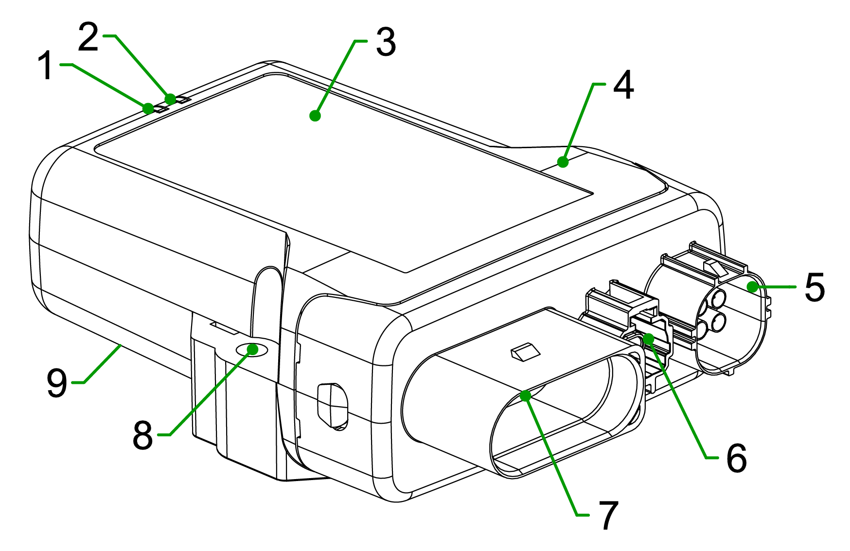
| # | Item | # | Item | |
|---|---|---|---|---|
| 1 | ON LED | 6 | Ethernet connector (SPE) | |
| 2 | STATUS LED | 7 | Main Plug connector | |
| 3 | Type label | 8 | Fixing holes | |
| 4 | Housing | 9 | Back-side label | |
| 5 | Antenna connector (WiFi/BLE, Cellular, GNSS) |
Type Label
The device type labels are located on the front and the back side of the housing and contain important regulatory information, including:
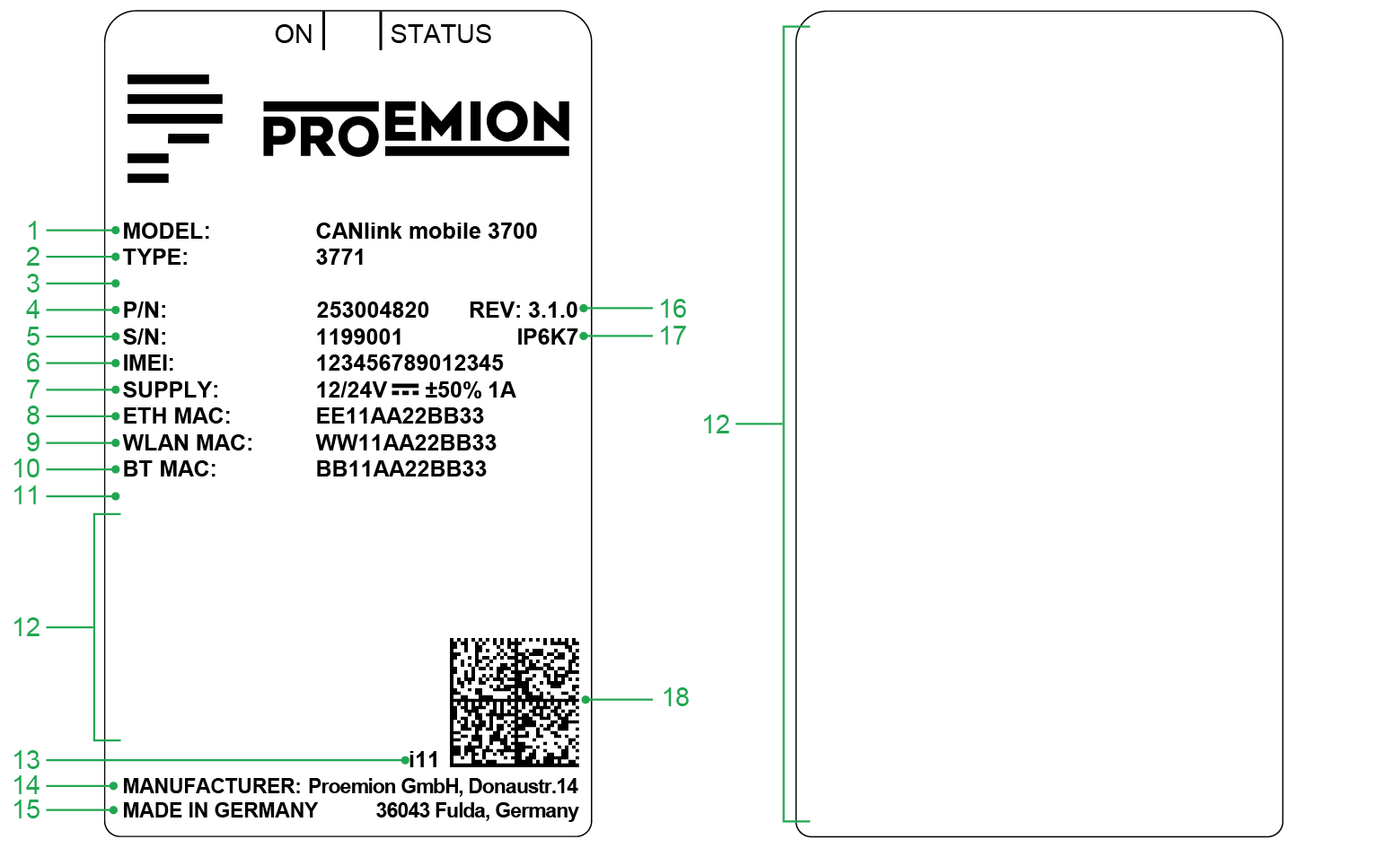
| # | Item | # | Item | |
|---|---|---|---|---|
| 1 | Model designation | 10 | Bluetooth Low Energy (BLE) MAC address | |
| 2 | Type | 11 | Reserved | |
| 3 | Reserved | 12 | Area of Regulatory and Compliance markings | |
| 4 | Part number | 13 | Product Change Index | |
| 5 | Serial Number | 14 | Manufacturer address | |
| 6 | IMEI number | 15 | Country of origin | |
| 7 | Power supply | 16 | Hardware version | |
| 8 | Ethernet MAC address | 17 | Protection class | |
| 9 | WLAN MAC address | 18 | Traceability code |
Note
Do not use solvents on the type label, as they may remove or destroy product information. The type label must not be removed. Record the information on the type label in case it becomes damaged. This information is required for product setup and support purposes.
Traceability Code
The device type label includes a Data Matrix code that serves as the traceability code. It provides a machine-readable representation of the device identification data.
Example:
253004059000000000001815014(I)357520074597168(W)D4CA6E7D0CAA(B)D4CA6E7D0CA9(E)D4CA6E7D0CAB
| Item | Description | Length |
|---|---|---|
| Part number | 253004059 |
9 |
| Reserved | 00000000000 |
11 |
| Serial number | 1815014 |
7 |
(I) followed by the IMEI Number |
357520074597168 |
15 |
(W) followed by the WLAN MAC Address |
D4CA6E7D0CAA - only certain types |
12 |
(B) followed by the Bluetooth MAC Address |
D4CA6E7D0CA9 - only certain types |
12 |
(E) followed by the Ethernet MAC Address |
D4CA6E7D0CAB – only certain types |
12 |
Options that are not available for a specific type are not shown in the code.
Interfaces and Connectivity
Depending on the device type, the device provides the following interfaces:
- Cellular communication (4G/LTE)
- GNSS for positioning data
- Wi-Fi/BLE
- Ethernet (Single-Pair Ethernet via dedicated connector)
- CAN interface via main connector
External antenna connectors may be available for cellular communication and GNSS and Wi-Fi/BLE.
Some variants include an integrated battery for temporary backup in case of power failure.
The battery is not intended as a permanent power source.
These interfaces allow connection to external devices such as PCs, smartphones, or tablets for data transmission, visualization, and analysis.
Operating Modes
The device supports the following operating modes for wireless CAN data transmission via Wi-Fi and BLE:
- CAN-BLE interface – connection to a BLE central device
Environmental Conditions
The device is designed for use in industrial environments as well as in earth-moving machinery.
Protection class IP6K7 is achieved only when all connectors are properly sealed using appropriate connectors or protection caps.
For installation details, see:
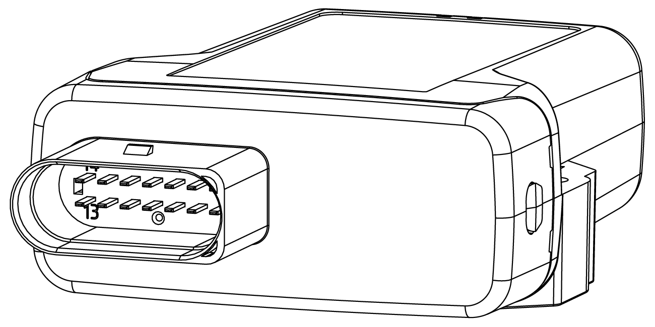
Available Models and Types
All Types in the table are Standard Variants.
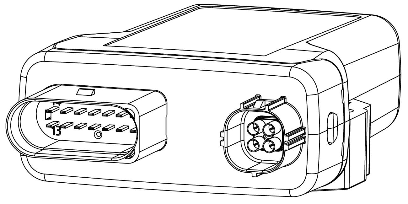
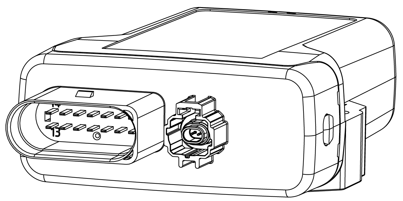
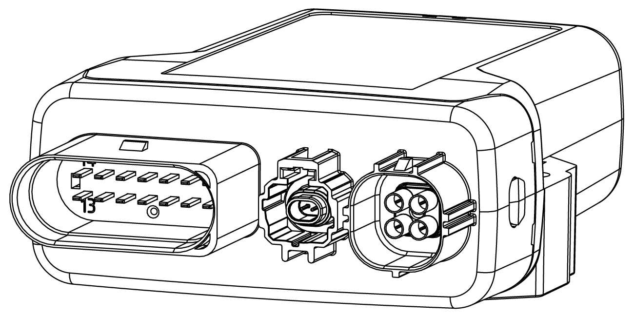
| Housing Form | Type | Part Number | Battery | Antenna | Ethernet |
|---|---|---|---|---|---|
 |
3733 3737 |
253004822 253004813 |
- ✓ |
Integrated Integrated |
- - |
 |
3773 3777 |
253004823 253004814 |
- ✓ |
External1 External1 |
- - |
 |
3731 | 2530048242 | - | Integrated | ✓ |
 |
3771 | 2530048202 | - | External1 | ✓ |
Note: Customer Specific Variant (Type 3721, Part Number 253004400, Housing Type MT14) is also available. The features External Antenna, Battery, Ethernet (SPE), LIN, 1-Wire, Digital Output and CAN3 are not available.
Scope of Delivery
- CANlink mobile 37xx
- Instruction Sheet with brief CE declaration
The Launch Kit must be purchased additionally to connect and use the device.
Launch Kit
The Launch Kit includes all hardware components required to commission the CANlink® mobile 3700 device.
Note
Access to the DataPlatform is not included by default. It must be explicitly requested and included in both the quotation and the final sales order.
Scope of Delivery
37xx Launch Kit Part Number: 253000176
The kit contains the following components:
| Component | Description | Part Number |
|---|---|---|
| Starter cable | 6 open leads, 2 D-Sub connectors, 1 power connector, 2 m | 136000246 |
| Main connector cable | 14-pin (Micro Timer II, COD.1), open wire ends, 2 m | 136000198 |
| CAN bus terminator | D-Sub/D-Sub, 120Ω | 157000033 |
| Power supply unit | 24 V / 0.83 A / 20 W, incl. international plugs | 257004007 |
| USB cable | 2 m (USB-C to USB-C) | 136000244 |
| Mounting kit | M5, housing GH120x | 141000017 |
| CANlink® Connector kit | Connector kit for CANlink device interfaces (power, CAN, I/O) | 132600031 |
| External roof antenna | LTE/GNSS/Wi-Fi, 3 m cable, HFM-Quad connector (see External Roof Antenna) | 157000136 |
| Antenna Mounting Aid | Centering aid required to mount the external antenna | 157012002 |
Accessories
The following accessories are compatible with CANlink® mobile 3700:
| Component | Description | Part Number |
|---|---|---|
| Launch Kit | CANlink® mobile 3700 Launch Kit | 253000191 |
| CANlink® Connector kit | Connector kit for CANlink device interfaces (power, CAN, I/O) | 132600031 |
| External roof antenna | LTE/GNSS/Wi-Fi, 3 m cable, HFM-Quad connector (see External Roof Antenna) | 157000136 |
| Main connector cable | 14-pin (Micro Timer II, COD.1), open wire ends, 30 cm | 136000188 |
| Main connector cable | 14-pin (Micro Timer II, COD.1), open wire ends, 2 m | 136000198 |
| Mounting kit | M5, housing GH120x | 141000017 |
| CANlink® mobile Opening Tool | For opening the device housing (see CANlink mobile Opening Tool manual) | 157012001 |
| Single-pair Ethernet cable | 2 m (H-MTD to H-MTD) | 136000245 |
| Starter cable | 6 open leads, 2 D-Sub connectors, 1 power connector, 2 m | 136000246 |
| USB cable | 2 m (USB-C to USB-C) | 136000244 |
Software Tools
The following software tools support commissioning, configuration, and maintenance of the device.
All tools can be downloaded from the Proemion Download Center.
| Software | Description |
|---|---|
| Proemion Configurator | Configuration and parameterization of CANlink devices |
| Proemion Firmware Programmer | Firmware flashing and update of CANlink devices |
| Remote Service Tool | Remote access and service operations on connected devices |
| CANlink DeviceAnalyzer | Diagnostics and analysis of device logs |
CANlink® mobile light
With the CANlink® mobile light, Proemion offers a concept to new customers who want to gradually adapt to a telematics system.
The CANlink® mobile light has a lower starting price and the same properties as any device from the CANlink® mobile, i.e. the same hardware, firmware and configuration.
CANlink® mobile light devices are tied to certain hosting plans that limit the amount of data and features available to those CUs.
The CU can be later upgraded in the DataPortal to access less limited hosting plans by paying an additional one-time fee, see CANlink® mobile light Upgrade.
Safety Instructions
This section contains safety instructions that must be followed to prevent injury, death, or damage to the device.
Intended Use
The device is designed for use in industrial environments as well as in earth-moving machinery.
The device is not intended for safety-related applications.
Foreseeable Misuse
The device must not be used in the following ways:
- Use in safety-related or safety-critical applications (e.g. according to ISO 26262)
- Use in potentially explosive atmospheres
- Use as a permanent power source via the internal battery
- Cleaning with high-pressure equipment (e.g. pressure washer)
- Any use outside the specified environmental and operating conditions
Qualified Personnel
The device must only be installed, commissioned, and serviced by qualified personnel.
Qualified personnel are trained technicians or electricians with knowledge of:
- Electrical systems
- Fieldbus communication (e.g. CAN)
- Applicable safety regulations
Personnel must have read and understood this documentation and have access to it at all times.
The responsible organization must ensure that only qualified personnel work with the device.
Functional Safety Restrictions
DANGER: Use in safety-related applications
Risk of severe or fatal injury.
The device operates using wireless communication. Data transmission cannot be guaranteed at all times due to possible network limitations, interference, or device malfunctions. The device is not designed, certified, or authorized for use in functional safety or safety-related applications (e.g. according to ISO 26262). Any failure, misconfiguration, or misuse may lead to malfunction of safety-critical systems.
- Never use this device in applications where human safety depends on its correct operation.
- Never use the device to influence or interfere with safety-relevant communication (e.g. powertrain CAN or other safety-related networks).
- The system integrator is responsible for ensuring that the device does not affect safety functions.
- Do not rely on wireless communication for critical or safety-relevant data transmission.
Explosion and Hazardous Environments
DANGER: Explosion hazard
Risk of severe or fatal injury.
Operation of electrical equipment in potentially explosive atmospheres may cause ignition.
- Observe all applicable regulations for hazardous areas.
- Do not install antennas near flammable substances (e.g. fuel tanks).
Aircraft Restrictions
DANGER: Interference with aircraft systems
Risk of severe or fatal injury.
Radio frequency emissions may interfere with aircraft communication systems.
- Disconnect the power supply before entering an aircraft.
- Ensure the device cannot be switched on during flight.
Electrical Safety
WARNING: Electric shock
Risk of severe or fatal injury.
- Do not use the device if there is visible damage.
- Do not open or repair the device.
- Repairs must only be carried out by the manufacturer.
Radio Frequency (RF) Exposure
WARNING: RF exposure and interference
Risk of severe or fatal injury.
Radio frequency emissions may interfere with medical and electronic equipment.
- Keep a minimum distance of 20 cm between antennas and persons.
- Do not operate the device near medical equipment (e.g. pacemakers) without verifying compatibility.
- Follow local regulations in hospitals and sensitive environments.
Installation and Power Supply Risks
WARNING: Improper installation or power supply
Risk of injury or device damage.
- Installation must be performed by qualified personnel.
- Protect the power supply circuit with an external 2 A fuse.
- Disconnect all connections before working on the device.
Mechanical Protection
Risk of property damage
The device is protected against mechanical impacts according to class IK07 (IEC 62262, impact energy 2 joules).
- If higher protection is required, additional external protection must be provided.
- If necessary, install external protection measures such as protective housings or shields to protect the device from external influences (e.g. water spray or mechanical impact).
Device Integrity and Handling
Risk of property damage
Improper handling may lead to device malfunction or damage.
- Do not use damaged cables or connectors.
- Ensure all connections are correctly assigned and not forced.
- Do not expose the device to solvents.
- Do not immerse the device in liquids.
- Ensure all connectors are properly sealed to maintain protection class (IP).
Cleaning and Environmental Limits
Risk of property damage due to water exposure
The device is resistant to water jets according to IPxK5. Higher pressure or flow rates may cause damage.
- Do not clean the device with a pressure washer.
Antenna Placement
Interference due to incorrect antenna positioning
Improper antenna placement may reduce performance or cause interference.
- Maintain a minimum distance of at least 1/4 wavelength between antennas.
- Avoid distances that are multiples of the wavelength.
- Do not operate antennas together with other transmitters unless properly evaluated.
Features
Modes and I/O
Online Mode
With Online mode, the device enables seamless, real-time monitoring and data management during machine operation.
You can record CAN messages, GNSS data, and internal sensor values (e.g., acceleration and gyro) while your machine is running. The device automatically stores all data in nonvolatile memory and uploads it to the DataPlatform when a connection is available. Depending on the device features, you can also log custom data from I/O functions or GNSS receivers, making it easy to track process variables or environmental conditions.
At the same time, you can transmit CAN messages and GNSS data in real time via BLE, Wi-Fi, or the mobile network. This allows for live monitoring of machine parameters, instant adjustments, and bidirectional communication with external systems. Custom CAN messages can be sent to the device from external sources, enabling flexible integration into your workflow. Alternatively, the device can use a Wi-Fi®, or BLE connection to receive/send data from/to an external receiver, e.g. the CANlink wireless, and have bidirectional communication between two local CAN interfaces.
Real-time data transmission requires a permanent connection between the device and the user software or the DataPlatform.
Note
Incoming Realtime sessions can be blocked through Wi-Fi®, BLE, or mobile via the object 0x3333:0x2B when >0, which can be set via the configuration or via the CANopen object dictionary from any external source.
This Online mode consolidates all data handling into a single workflow and ensures that your operations are continuously monitored and fully connected to the DataPlatform.
Further information on Connection Types and data storage, including Time Series Handling, can be found in the DataPortal user manual.
Input/Output Functions
The device allows monitoring and recording of process-relevant signals through its input/output functions. You can use the inputs to log status information from machines or devices, such as switch and sensor states, and to track operational parameters. The data collected via the input/output functions can be visualized locally or forwarded to the DataPlatform via CAN for further analysis.
The CANlink® mobile 3700 provides 2 analog inputs, suitable for monitoring key signals or selected machine parameters.
The digital output can be used to control external devices or indicate system states, for example by triggering alarms, status lights, or relays. Custom logic can be implemented to respond to specific input conditions, enabling flexible automation and monitoring.
Connectivity
Cellular Interface
The device is equipped with a cellular interface for reliable mobile data transmission. It supports common mobile network standards
(4G/LTE)
and automatically selects the best available network to ensure optimal coverage and performance. Seamless fallback mechanisms guarantee continuous connectivity. The interface enables secure bidirectional data exchange for remote monitoring and control applications. Support for specific network standards may vary depending on the device variant.
Encrypted Data Transfer
The device supports encrypted data transfer to the DataPlatform in accordance with the TLS standard (Transport Layer Security).
TLS encryption is enabled by default upon delivery, and after a device reset to factory settings. No user intervention is required to activate encryption.
Note
Using data encryption is considered a cybersecurity best practice. Proemion strongly recommends keeping encryption enabled at all times.
Technical Details
The variables required belong to the DEVICE VARIABLES object dictionary group.
| Variable | Function |
|---|---|
| ENABLE ENCRYPTED DATA TRANSFER | 1 = enable encrypted data transfer |
| REMOTE SERVER PORT | 61200 = port for encrypted data transfer |
TLS encryption is mandatory. The ENABLE ENCRYPTED DATA TRANSFER variable can only be set to 1 (enable TLS); any attempt to set it to 0 is invalid.
Note
Encrypted data transmission may be prohibited in some countries. Please observe local regulations on encrypted data transfer.
Sensors
Acceleration Sensor
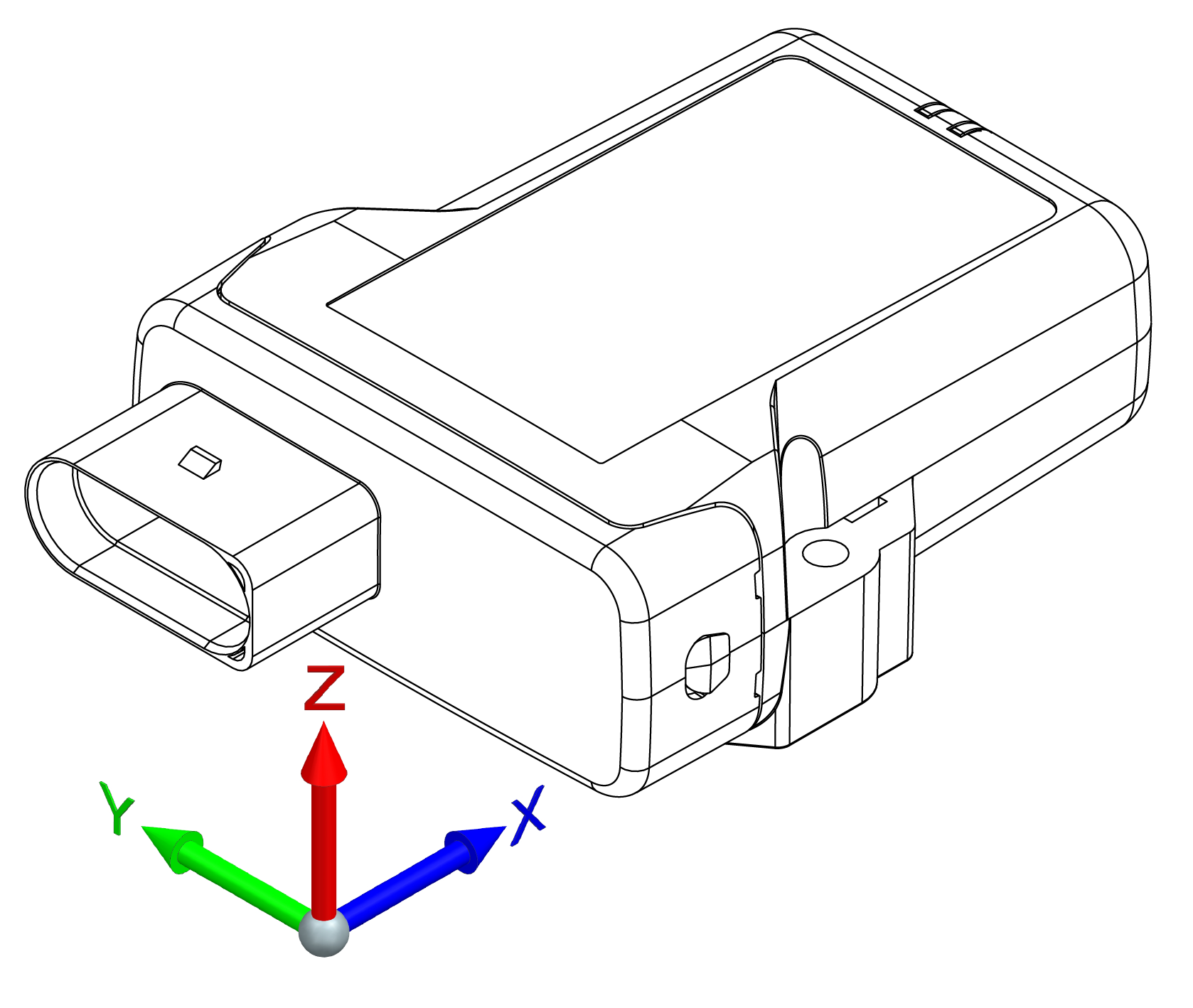
The acceleration sensor registers and evaluates accelerations in the directions of the X, Y, and Z axes, and sends them via the CAN bus.
Note
The sensor is not calibrated.
Gyro Sensor
The 3-axis gyro sensor registers and evaluates the angle speeds in the X, Y, and Z axes and sends them to the CAN bus.
Note
The sensor is not calibrated.
Geolocation Features
The CANlink® mobile 3700 provides two primary methods for tracking machine movements and operational areas: GeoLeash and GeoFence. Both functions allow monitoring of machine relocation, but they differ in configuration effort and specific use cases.
The following documentation explains how to configure and use the GeoFence and GeoLeash functions, describes the related variables, and provides guidance on using these functions.
GeoFence Mode
The device is provided with a geofence monitoring function. This allows you to monitor whether the device is located inside or outside a pre-defined “fenced” area and when the device crosses the fence.
There are three ways to define the fence:
- Define center and radius of a circle. The center of the circle is defined as a fixed point.
- Define center and radius of a circle. The current position on enabling the function is used as the center of the circle.
- Two opposite points are defined for a rectangle. The variables belong to the DEVICE VARIABLES > INTERNAL GEOFENCE object dictionary group.
| Variable | Function |
|---|---|
| GEOFENCE - MODE | 0 = Geofence disabled 1 = GeoFence enabled, circle center and radius defined 2 = GeoFence enabled, set current position as circle center and define radius (switches to mode 1 internally)1 3 = GeoFence enabled, rectangle 4 = GeoLeash enabled, location monitoring, COORDINATE 2 > LONGITUDE / RADIUS variable is a condition. |
| GEOFENCE - COORDINATE 1 > LONGITUDE | Longitude for center of the circle or first corner of the rectangle |
| GEOFENCE - COORDINATE 1 > LATITUDE | Latitude for center of the circle or first corner of the rectangle |
| GEOFENCE - COORDINATE 2 > LONGITUDE / RADIUS | GeoFence Mode Circle: Radius of the circle GeoLeash Mode: Line length (unit: meters)GeoFence Mode Rectangle: Degree of longitude of second corner (Unit: Decimal degree, -180 ... 180) |
| GEOFENCE - COORDINATE 2 > LATITUDE | Latitude for the second corner of the rectangle |
GeoFence Status
The GeoFence status can be used to trigger an event internally. The GeoFence status is updated every 2 seconds. Every time the GeoFence status changes, the time is written to a variable.
The variables belong to the object dictionary group DEVICE VARIABLES.
| Variable | Function |
|---|---|
| GEOFENCE STATUS | 0x00 = device is outside the fence 0x01 = device is inside the fence 0xFF = status unknown (e.g. because no position data is available) |
| GEOFENCE - STATUS CHANGE UTC TIME | Time of GeoFence status change |
For detailed information on creating objects, see Creating Object Dictionary Groups and Objects.
GeoLeash
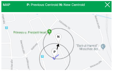
The GeoLeash function enables you to monitor and display the location of the machine.
In this case, the location offset is determined by an adjustable limit value. The minimum limit value for the tolerated location offset is 100 meters.
The DataPortal can be used to activate the GeoLeash function and define the area to be monitored.
Note
The GeoLeash and device internal Geofence functions cannot be used simultaneously.
Please be aware that the GeoLeash function must be supported by the installed firmware. In case of problems, update to the latest firmware.
Further information on the GeoLeash function is available in the DataPortal, see Widget Catalog > GeoLeash.
-
Mode
2is a one-time command, not a persistent mode: once activated, the device takes its current position (or the next position fix, if none is available yet) as the circle center and then switches GEOFENCE - MODE back to1internally. ↩
Hardware
Cables
Cables
The device supports different cable types for specific use cases:
- Starter Cable – used for power supply and CAN communication
- Diagnostics Cable – used for device diagnostics and debugging via USB
- Adapter Cables – used to integrate the device into existing systems or to adapt legacy connections
Detailed information for each cable type, including connector pinouts, is provided in the following sections.
Cable Installation
The following instructions apply to the installation and routing of cables for the device.
Proper cable installation is essential to ensure reliable operation and to prevent damage to connectors and the device.
- Assemble the cables in accordance with the recommendations of the cable or connector manufacturer.
- Ensure a sufficient bending radius of all cables during installation.
- Ensure appropriate strain relief for all cables.
- Fasten the cable harness near the main connector to prevent mechanical stress on the connector and housing.
- Protect and secure the cables within the machine to avoid damage caused by vibration or movement.
Starter Cable
The starter cable, 2 m (part number 136000246), is intended for initial setup, testing, and commissioning of the device.
It is used to connect the device to a host system and external interfaces such as CAN and power supply.
The cable is equipped with the following connectors and open wires:
- X1: Main Plug connector
- X2: CAN interface
- X3: CAN interface
- X4: Power supply connector
- 6 open wires
X1 - Main Plug Connector
| Pin | Designation | Color | Description |
|---|---|---|---|
| TBD | TBD | TBD | TBD |
6 Open Wires
Starter cable for main plug connector with 6 open wires.
| Designation | Color | Description |
|---|---|---|
| TBD | TBD | TBD |
X2 - CAN Interface
| Pin | Designation | Color | Description |
|---|---|---|---|
| TBD | TBD | TBD | TBD |
X3 - CAN Interface
| Pin | Designation | Color | Description |
|---|---|---|---|
| TBD | TBD | TBD | TBD |
X4 - Power Supply Connector
| Pin | Designation | Color | Description |
|---|---|---|---|
| TBD | TBD | TBD | TBD |
Diagnostics Cable
The USB cable, USB-C to USB-C, 2 m (part number 136000244) is intended for debugging and diagnosis of the device.
Only USB 2.0 Full Speed (12 Mbit/s) is supported; SuperSpeed functionality is not available. The USB interface is located inside the device and requires opening the housing, see CANlink mobile Opening Tool manual.
The cable has two identical USB-C, male connectors.
Connectors
| Pin(s) | Signal | Description |
|---|---|---|
| A4, A9, B4, B9 | VBUS | +5 V bus voltage (device is self-powered; not used to supply power) |
| A7, B7 | D− | Data− (bidirectional) |
| A6, B6 | D+ | Data+ (bidirectional) |
| A5 | CC1 | Configuration channel (pull-down to GND) |
| B5 | CC2 | Configuration channel (pull-down to GND) |
| A1, A12, B1, B12 | GND | Ground |
| Remaining pins | - | Not connected |
Adapter Cables
The following adapter cables are applied when replacing old devices.
Adapter Cable to M12, 5-Pin
The Adapter Cable to M12, 5-Pin (part number 136200001).
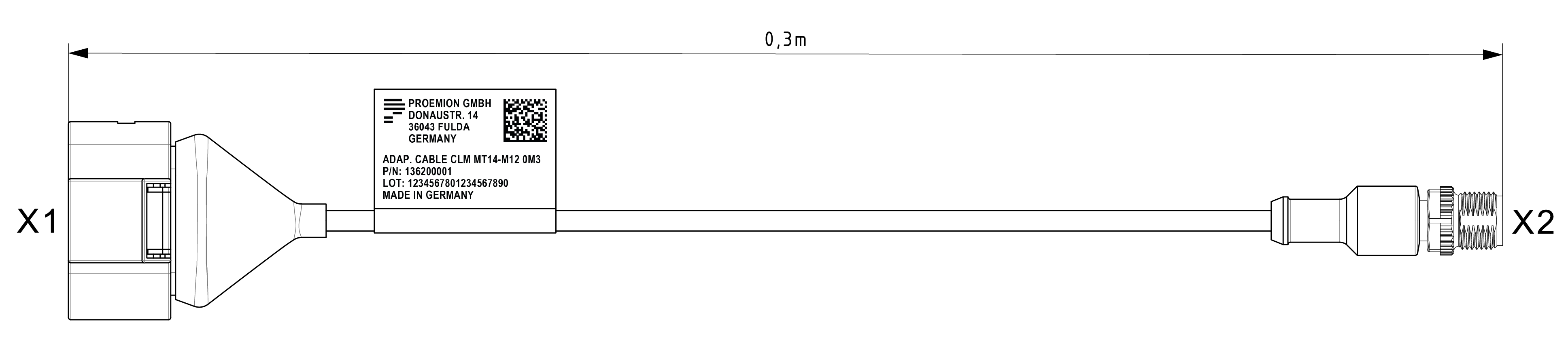
It has the following connectors:
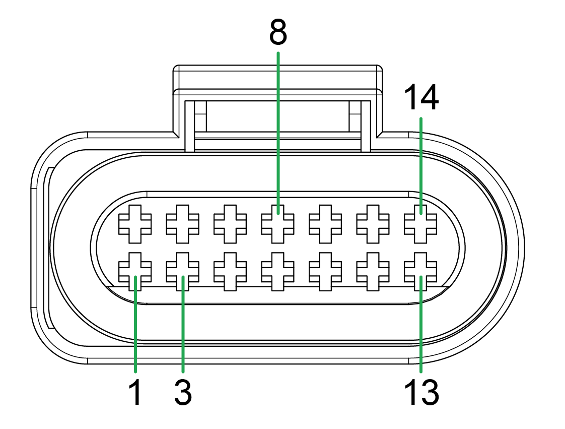
- X1 - Micro-Timer II socket connector, 14-pin, female, code I
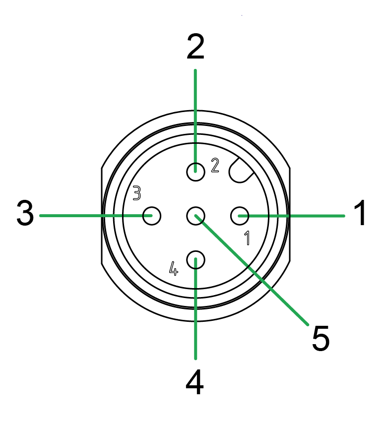
- X2 - M12 connector, 5-pin, male, code A
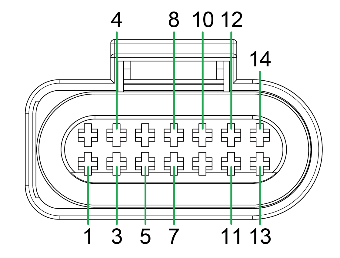
X1 - Micro-Timer II socket connector, 14-pin, female, code I
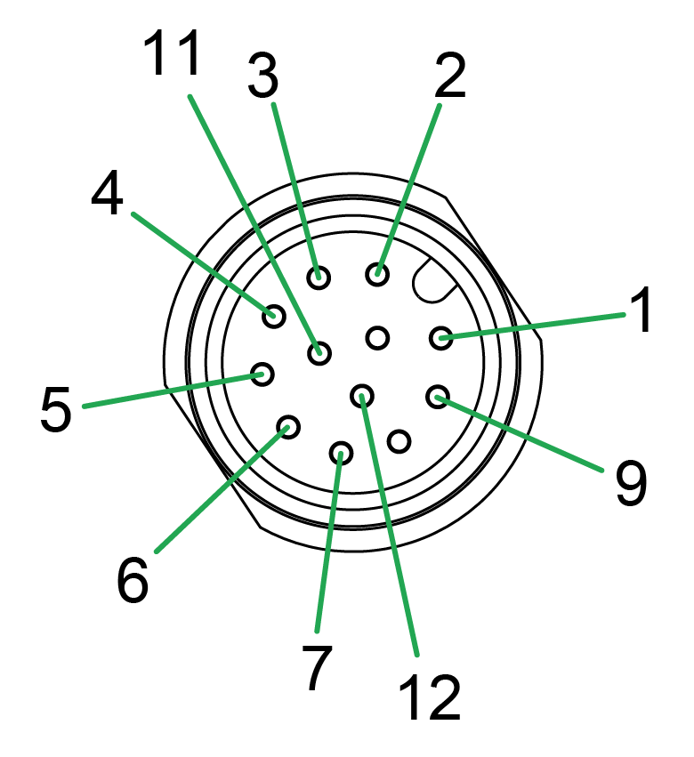
X2 - M12 connector, 5-pin, male, code A
Adapter Cable to M12, 12-Pin
The Adapter Cable to M12, 5-Pin (part number 136200002).
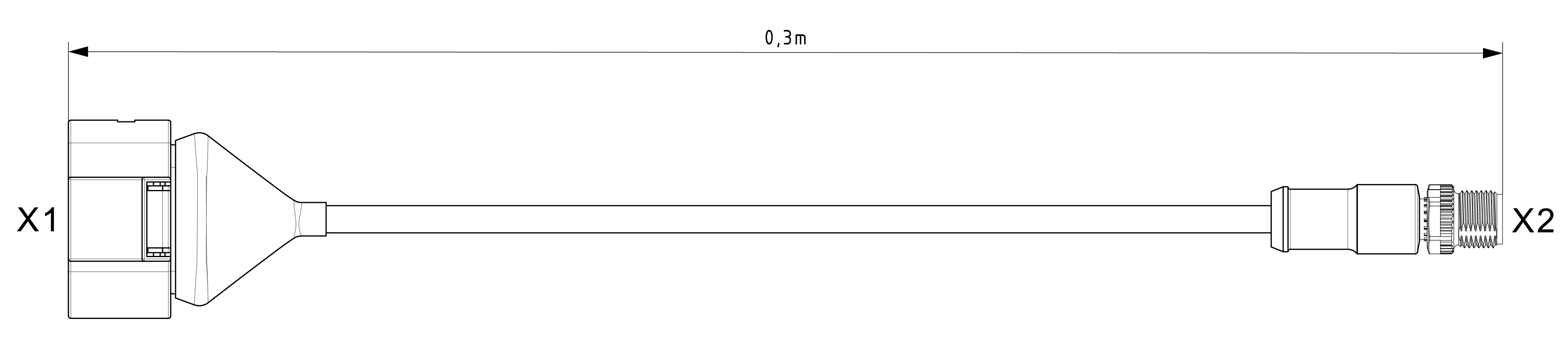
It has the following connectors:
- X1 - Micro-Timer II socket connector, 14-pin, female, code I
- X2 - M12 connector, 5-pin, male, code A
X1 - Micro-Timer II socket connector, 14-pin, female, code I
X2 - M12 connector, 5-pin, male, code A
Indicator Elements
Two LEDs are installed on the front of the device to indicate functions and status.
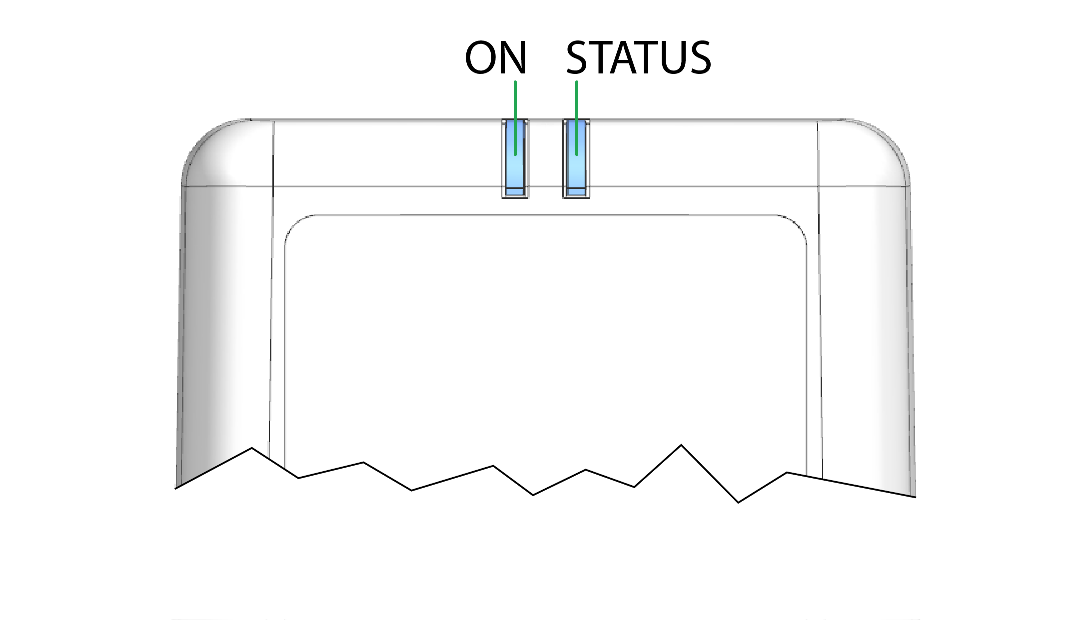
The LEDs have the colors red, green, and blue. When several colors are active simultaneously, the LEDs also light up in magenta, orange, or turquoise.
The following tables show possible LED statuses:
ON LED
The ON LED indicates the power supply status.
| Color | State | Meaning |
|---|---|---|
| - | Off | Device switched off or in sleep mode |
| Green | On | Device switched on, terminal 30 voltage in permitted range |
| Red | On | Device switched on, terminal 30 voltage outside permitted range |
| Green | Flashing | Device in diagnosis or update mode |
| Orange | On | Device is in device reset mode. See also LEDs during certain operating modes |
STATUS LED
The STATUS LED indicates the operating status of the active connections. The various colors reflect the respective priority, from 6 (low) to 1 (high). If several modes are active simultaneously, the STATUS LED always indicates the status with the highest priority (smallest number).
| Color | State | Connection | Priority | Meaning |
|---|---|---|---|---|
| Green | On | Various | - | No Error. Device is connected to the DataPlatform |
| Blue | On | Cellular internet | 1 | Not connected to the DataPlatform. |
| Orange | On | CAN 1 | 2 | Error on CAN 1 interface. |
| Red | On | CAN 2 | 3 | Error on CAN 2 interface. |
| White | On | CAN 3 | 4 | Error on CAN 3 interface. |
| Magenta | On | GNSS | 5 | No position / antenna recognized. |
| - | Off | Wi-Fi / BLE | 6 | LED On is also off, the device is switched off. LED On is on, Not connected to any network / device. |
If there are no errors with the current connection (Cellular, CAN1/2/3, GNSS, wireless interfaces), the STATUS LED lights up green.
When the connection is active, e.g. communication with the DataPlatform, the STATUS LED flashes from time to time. ("Activity flash").
In the event of a fault, the STATUS LED only displays the status with the highest priority.
Example: The device does not recognize any GNSS position (priority 5 = magenta) and has no Cellular connection (priority 1 = blue). The STATUS LED lights up blue.
LEDs during certain operating modes
| LED | State | Meaning |
|---|---|---|
| ON STATUS |
 |
Configuration update in progress via the CAN interface. |
| ON STATUS |
 |
Active file transfer. A CAN message is received (flashes_orange) and sent to the DataPlatform (flashes_blue). |
| ON STATUS |
 |
Active data transmission. |
| ON STATUS |
 |
Device initializing after switching on. |
| ON STATUS |
 |
Configuration update in progress via the DataPlatform. |
| ON STATUS |
 |
Remote firmware update in progress via the DataPlatform. |
| ON STATUS |
 |
Reset (0x1011:0x64) the device via the CAN. |
| ON STATUS |
 |
Transmission of the GNSS position and the keep-alive message. Display varies depending on configured polling interval. |
SIM cards
eSIM card
All device types are equipped with an integrated eSIM card.
On delivery, the eSIM card already has an eSIM profile with all the necessary communication settings.
Potential connectivity loss with custom SIM card
The device cannot establish an online connection to the DataPlatform when using a customer specific SIM card and wrong firewall settings at the SIM provider. IP addresses of the DataPlatform may change without prior notice.
- Make sure that the SIM card provider is not using IP address based white-listing for any DataPlatform communication.
- Make sure that - if white-listing is required - the corresponding DNS names are white-listed at the SIM provider's firewall.
On delivery, the device's eSIM card is not yet activated.
After registration of the device, activation of the eSIM card is triggered automatically.
Usually this process takes about 15 minutes. In exceptional cases it can take up to 1 working day.
Nano-SIM card
The device also provides a nano-SIM slot.
Potential connectivity loss with custom SIM card
The device cannot establish an online connection to the DataPlatform when using a customer-specific nano-SIM card with incorrect firewall settings at the SIM provider. IP addresses of the DataPlatform may change without prior notice.
- Make sure that the SIM card provider is not using IP address based white-listing for any DataPlatform communication.
- Make sure that - if white-listing is required - the corresponding DNS names are white-listed at the SIM provider's firewall.
Malfunction due to defective nano-SIM cards may occur.
- Make sure that the specification of the selected nano-SIM card meets the environmental requirements of the device.
- Ensure that the dimension of the selected nano-SIM corresponds to form factor 4FF.
Battery
Some device types feature an integrated battery (lithium-polymer).
The integrated battery allows it to send logged CAN and position data via the cellular radio interface even if the power supply from the main plug connector is interrupted. The device is not designed for permanent battery operation.
On delivery, the integrated battery is charged by approx. 30%. Before you use the device, charge the battery fully.
A fully charged battery can back up a power failure of
The following examples provide an overview of the battery runtimes in various application cases.
Example 1:
The rechargeable battery integrated is charged to 100% and the device is permanently switched on and online. The device transmits one file per minute.
The battery runtime is TBD.
Example 2:
The integrated battery is charged by 100% and the device is permanently in Sleep mode.
The device switches on cyclically every 24 hours and is online for 5 minutes to transmit the current position and certain internal device parameters. Then the device automatically switches back to Sleep mode.
The battery runtime is TBD.
Example 3:
The integrated battery is charged by 100% and the device is permanently in Sleep mode.
The device goes online only once, triggered by the acceleration sensor, and transmits the current position (theft monitoring without external power supply).
The battery runtime is TBD.
The values stated in the examples can deviate depending on the use purpose, the setup conditions (@ 20°C battery temperature) and the configured device variable GO TO SLEEP VOLTAGE, see Important device variables.
Note on the integrated battery
-
The integrated battery is charged using the power supply via terminal 30 and charging is only possible in a limited temperature range of:
0 °C … +35 °C (+32 °F … +95 °F) -
Battery operation of the device is only possible in a limited temperature range of:
-20 °C … +50 °C (-4 °F … +122 °F)
Note the following information about use of the integrated battery
-
The integrated battery has a limited service life.
After 500 charging cycles, contact the Proemion service to replace the integrated battery, see Chapter Service and Support.
The number of charging cycles can be read out via theBATTERY - CYCLE COUNTdevice variable. See Battery. -
Perform three complete charging and discharging cycles to achieve the full performance capability of the integrated battery.
- During battery operation, it is not possible to use the digital output or the LIN interface.
Getting Started
Connecting the Device
Install the nano-SIM card
This chapter describes how to properly install the nano-SIM card in the device.
Note
Ensure the device is powered off before proceeding. Observe all ESD protection measures: wear a grounding wrist strap, work on an antistatic surface, and avoid touching any other components on the PCB.
Open the Housing
Open the housing using the CANlink® mobile Opening Tool. For detailed instructions, refer to CANlink mobile Opening Tool manual.
Note
Open the housing only for the purpose of inserting or replacing the nano-SIM card. Use only the approved CANlink® mobile Opening Tool and follow the instructions carefully.
Insert or Replace the nano-SIM card
The following figure shows the steps required to insert or replace the nano-SIM card.
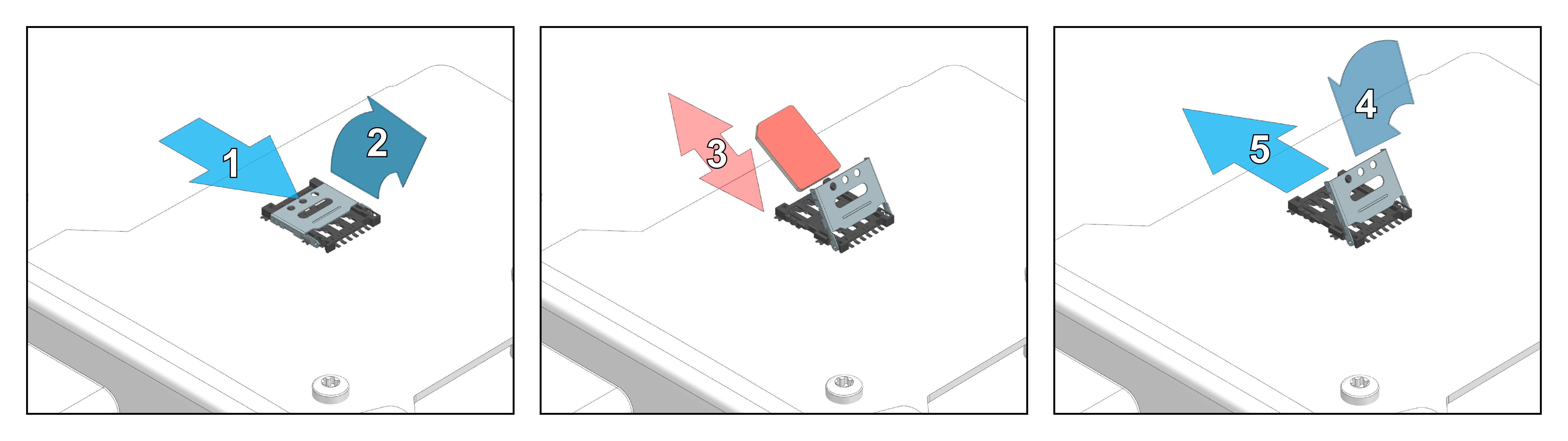
Note
Handle the nano-SIM card with care. Do not force or bend the nano-SIM card during installation.
The nano-SIM card holder is located on the top side of the PCB assembly.
To install the nano-SIM card, proceed as follows:
- Slide the metal shell to unlock the SIM card holder.
- Flip the metal shell open.
- Insert or replace the nano-SIM card carefully. Make sure the chamfered corner aligns correctly with the holder.
- Fold the metal shell back down.
- Slide the metal shell into the locked position until it is securely locked in place.
Close the Housing
Note
Before closing the housing, ensure the nano-SIM card lies flat and is properly seated in the holder.
The housing is equipped with two click fasteners, which must be closed separately and sequentially. Apply force only at the designated pressure points. These pressure points are located at the outer edge of the cover on the short sides, aligned with the click fasteners. Closing the housing requires a higher level of force at these pressure points.
Mount the Device
Mount the device using two socket-head screws (M5). Insert the screws into the mounting holes on the sides and fasten them to the mounting surface. Tighten the screws with a torque of 2.2 Nm.
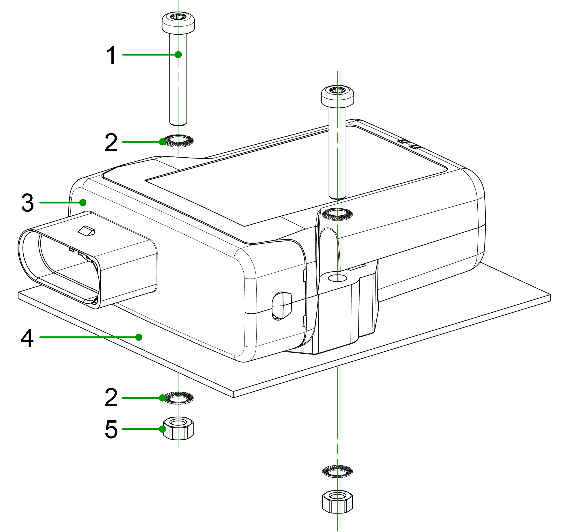
- Socket-head screw
DIN 912 – M5 x 30 mm - Lock washer
M5, di/da = 5.3 / 9 mm - CANlink® mobile 3600
- Mounting surface
D = 3 mm - Hexagon nut
DIN 934 / ISO 4032 – M5
For detailed dimensions, refer to Technical Drawings.
Mounting Orientation
Follow these guidelines to ensure correct mounting orientation for proper functionality, environmental protection, and radio signal reception.
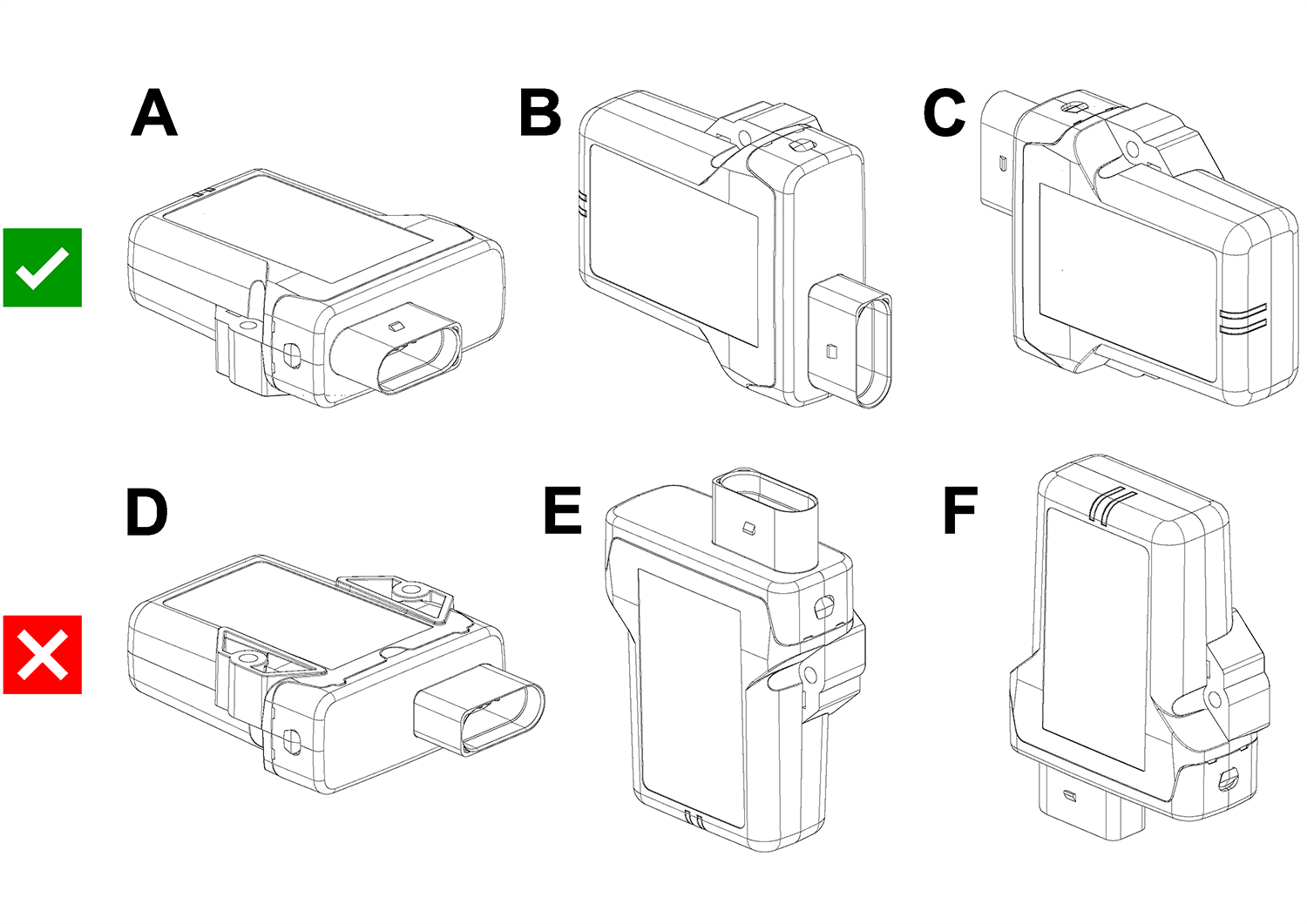
The illustration below shows the mounting orientations of the device:
- A–C: Allowed, ensures water ingress and fire protection
- F: Conditionally allowed, fire protection only; no water exposure permitted
- D–E: Not allowed, no water or fire protection
Only use the mounting orientations shown here.
Fire Protection
The LED view elements do not comply with the flammability class required for a fire protection housing.
Plug Orientation
- Plugs must point to the left or right
- Do not mount with plugs pointing upwards
- Avoid mounting with plugs pointing downwards (risk of water ingress)
Mounting in Wet Environments
For installations exposed to weather or other sources of water, ensure that the mounting prevents water ingress and accumulation.
- Ensure a gap of ≥ 5 mm between the housing and the mounting surface to prevent capillary action
- Select a mounting orientation that allows water to drain and prevents water retention
- Ensure that no water accumulates around the pressure-compensation element
If exposure to water cannot be avoided:
-
Install protective covers or shrouds if the device is exposed to water1.
-
Use nonmetallic materials (e.g. plastic) to avoid interference with radio signal reception
- Use spacers or a mounting plate if required
Additionally:
- Ensure that cable ends are properly sealed to prevent water ingress due to capillary action
Avoid mounting the device in positions directly exposed to rain or intense sunlight, as this may affect the ingress protection.
-
Protective covers are not distributed by Proemion. They must be obtained directly from manufacturers (e.g., Schlemmer; minimum order quantity may vary). ↩
Operation
The following sections contain information on operating the device and the Proemion Configurator software
Proemion Configurator
Configure the device using Proemion Configurator.
You can find additional information on individual objects (DEVICE VARIABLES) in Proemion Configurator under the Additional Information field for each object. Always use the latest version of Proemion Configurator with the updated information texts.
The Proemion Configurator software can be downloaded from the Download Center under: 03_Proemion Tools Software > 01_Software > 01_PROEMION Configurator.
Note
In case of problems, the Connectivity Check utility can be used to check the connectivity of our software tools with our services from your site's network.
Creating Object Dictionary Groups and Objects
You can use the Proemion Configurator tree structure to create, rename, or delete object dictionary groups or objects.
This chapter explains how to create object dictionary groups and objects.
The following example shows creation of the object RECEIVE MESSAGE PDO. This object is used to receive and log CAN messages.
To create the object, you need the CUSTOM CAN COMMUNICATION object dictionary group and then the RECEIVE CAN MESSAGES (PDOs) object dictionary group.
-
Start the Proemion Configurator software.
-
Choose FILE > OPEN from the menu and select the configuration file you want.
-
In the tree structure, open CUSTOM CAN COMMUNICATION > RECEIVE CAN MESSAGES (PDOs).
-
Right-click to open the context menu and select NEW OBJECT DICTIONARY GROUP > RECEIVE MESSAGE (PDOs)
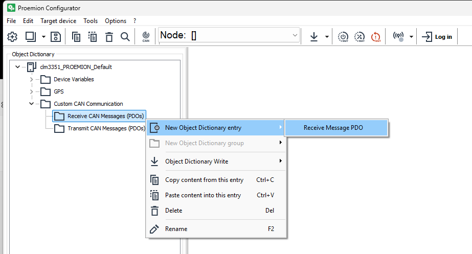
Figure 1: Object Dictionary Group - RECEIVE CAN MESSAGES (PDOS) -
In the NUMBER OF NEW OBJECTS field, enter how many objects (received messages) you want to create.
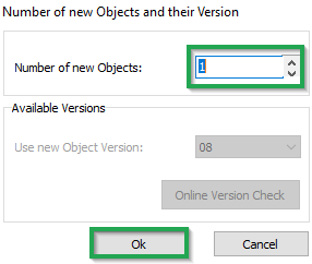
Figure 2: NUMBER OF NEW OBJECTS -
Click OK.
✓ The object RECEIVE MESSAGE PDO is created.
-
To rename an entry in the tree structure, click on the corresponding entry to select it. Click on the entry again to rename it.
Important device variables
This chapter provides information on important device variables that control the device functions.
Positioning
The device is equipped with a GNSS receiver. The GNSS receiver can process signals from the following satellite navigation systems:
-
GPS
-
GLONASS
-
BEIDOU
Note
The GNSS functionality is automatically disabled in certain countries to meet cybersecurity requirements under the Radio Equipment Directive (RED). This measure ensures compliance with local type approval regulations and legal restrictions on location services.
Set the combination of the satellite systems in the POSITIONING > MODE (GNSS) variable. The POSITIONING > MODE (GNSS) variable belongs to the DEVICE VARIABLES > POSITIONING object dictionary group.
| Variable | Function |
|---|---|
| POSITIONING - MODE (GNSS) | 0 = GPS only 1 = GPS + GLONASS 2 = GPS + BEIDOU 3 = GLONASS + BEIDOU 4 = GPS + GALILEO 5 = GPS + GALILEO + GLONASS + BEIDOU |
| Variable | Function |
|---|---|
| POSITIONING -- ANTENNA STATUS | Status of the antenna |
| POSITIONING - POSITIONING DATA VALID | Status of the position system. Indicates whether valid position data is available |
| POSITIONING - ACTIVE SATELLITES | Number of satellites used |
| POSITIONING - LONGITUDE | Longitude |
| POSITIONING - LATITUDE | Latitude |
| POSITIONING - ALTITUDE | Altitude of the antenna above sea level |
| POSITIONING - SPEED OVER GROUND | Speed over ground |
| POSITIONING - GPS ODOMETER | GPS-based measurement of kilometers traveled |
| POSITIONING - HEADING | Direction in relation to North |
Wi-Fi® and Bluetooth Low Energy (BLE)
Some types of the device are equipped with a radio module for Wi-Fi® and Bluetooth Low Energy (BLE). The DEVICE VARIABLES > LOCAL WIRELESS object dictionary group contains the following variables:
| Variable | Function |
|---|---|
| WLAN - ENABLE1 | Enable and disable the Wi-Fi interface |
| BLE - ENABLE | Enable and disable the BLE interface |
| WLAN - MAC ADDRESS | MAC address of the Wi-Fi interface |
| BLUETOOTH - MAC ADDRESS | MAC address of the BLE interface |
| BLE - DEVICENAME | BLE device name |
| WLAN/BLUETOOTH - FIRMWARE VERSION RADIO MODULE | Firmware version of the Wi-Fi module |
| WLAN/BLUETOOTH - BLE FIRMWARE VERSION RADIO MODULE | Firmware version of the BLE module |
You can find more information on further device variables in the explanatory texts in the Proemion Configurator software.
Input/Output Functions and Sensors
Depending on the hardware variant, the device is equipped with input and output functions.
You can measure voltages between 0 V and 15 V with the analog inputs.
The DEVICE VARIABLES > I/O, SENSORS, DIAGNOSIS object dictionary group contains the following variables:
| Variable | Function |
|---|---|
| OPERATION TIME TOTAL | Device operation time in seconds. |
| DEVICE TIME (UNIX_FORMAT) | Internal device time. The time is synchronized to UTC time by the GNSS satellites, NTP servers or the DataPlatform. |
| IO - DIGITAL OUTPUT | 0 = output off 1 = output on |
| IO - DIGITAL OUTPUT STATUS | 0 = output error 1 = output ok |
| IO - TERMINAL 30 VOLTAGE | Voltage on terminal 30 connector. |
| IO - TERMINAL 15 VOLTAGE | Voltage on terminal 15 connector. |
| IO - TERMINAL 15 (IGNITION) | 0 = input state low (< 2.3V) 1 = input state high (> 6V) |
| IO - DEVICE TEMPERATURE | Device internal temperature in °C |
| ANALOG INPUT 1 | Voltage on analog input 1 in Volts |
| ANALOG INPUT 2 | Voltage on analog input 2 in Volts |
| ACCELERATION - X-AXIS | Acceleration on the X-axis (in g) |
| ACCELERATION - Y-AXIS | Acceleration on the Y-axis (in g) |
| ACCELERATION - Z-AXIS | Acceleration on the Z-axis (in g) |
| GYROSCOPE - X-AXIS | Rate of rotation on the X-axis (in °/s) |
| GYROSCOPE - Y-AXIS | Rate of rotation on the Y-axis (in °/s) |
| GYROSCOPE - Z-AXIS | Rate of rotation on the Z-axis (in °/s) |
The variables IO - DIGITAL OUTPUT, IO - ANALOG INPUT1, and IO - ANALOG INPUT2 are available for the input/output functions. To enable and configure the input/output functions, you must create additional options.
-
Create the IO MODULE CONFIGURATION object dictionary group.
-
Click the right-hand mouse button on the IO MODULE CONFIGURATION object dictionary group.
-
In the context menu, click on NEW OBJECT DICTIONARY ENTRY > CHANNEL SETUP.
✓ You have created the objects ANALOG INPUT - CHANNEL 1, ANALOG INPUT - CHANNEL 2 and DIGITAL OUTPUT - CHANNEL 3.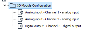
Figure 1: Input / Output Context Menu
Output Function
Define the settings for the output function under IO MODULE CONFIGURATION > DIGITAL OUTPUT - CHANNEL 3.
-
Select the object DIGITAL OUTPUT - CHANNEL 3.
-
In the CHANNEL CONFIGURATION list, select the configuration ON-OFF DIGITAL OUTPUT.
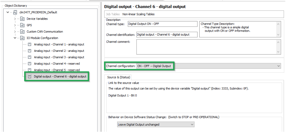
Figure 2: On - Off Digital Output
The following variables are available:
| Variable | Function |
|---|---|
| CHANNEL CONFIGURATION | Enable and disable the digital output. |
| BEHAVIOR ON DEVICE SOFTWARE STATUS CHANGE | Behavior on CANopen Mode STOP or PREOPERATIONAL. The output can retain its current value or be set to a defined value. |
Battery
Some types of the device are equipped with an integrated battery. The DEVICE VARIABLES > BATTERY object dictionary group contains the following variables:
| Variable | Function |
|---|---|
| BATTERY - CHARGE LEVEL | Current charge level (in %) |
| BATTERY - VOLTAGE | Measured voltage (in Volts) |
| BATTERY - CYCLE COUNT | Number of charge cycles so far |
| BATTERY - STATE OF HEALTH VALUE | Probable remaining capacity relative to nominal capacity (in %) |
| BATTERY - TIME TO EMPTY | Expected remaining time until full discharge (in Minutes) |
| BATTERY - FULL CHARGE CAPACITY | Probable capacity if fully charged (in mAh) |
| BATTERY - CURRENT | Current to or from the battery Value > 0: charging Value = 0: fully charged Value < 0: discharging |
| BATTERY - TEMPERATURE | Current temperature (in °C) |
| GO TO SLEEP VOLTAGE | Specifies the battery voltage threshold at which the device enters sleep mode. The value is defined in millivolts (e.g. 3500 = 3.5V, 3300 = 3.3V). |
Note
The GO TO SLEEP VOLTAGE device variable is not included in the default configuration and must be added manually if required.
Note
The integrated battery has a limited service life.
- Have the integrated battery replaced by our service department after 500 charging cycles. See Service and Support
Operation Time Counter
The device is equipped with an internal operation time counter.
The OPERATION TIME TOTAL object belongs to the DEVICE VARIABLES > I/O, SENSORS, DIAGNOSIS object dictionary group.
The operation time counter cannot be reset. The operation time counter runs as soon as the device is in Standard mode (not Sleep mode).
For detailed information on creating objects, see Creating Object Dictionary Groups and Objects.
-
The object dictionary variable names use the designation
WLANfor Wi-Fi. ↩
Power Management
To protect the device from damage and data loss, a correct wiring and configuration of the power management settings is mandatory. The main purpose of the power management settings is that the device has a safe shutdown before the supply voltage (terminal 30/31) is disconnected.
The required variables belong to the DEVICE VARIABLES > POWER MANAGEMENT object dictionary group. For detailed information on creating objects, see Creating Object Dictionary Groups and Objects.
The following subsections provide an overview of the individual power management functions.
Note
Wake up of the device is possible when at least one of following condition is fulfilled:
- The IO - Clamp 15 (Ignition) State is at level
high(> 6 V) - A CAN message is present at the CAN 1 or CAN 3 interface
- The Power Management - Acceleration Sensor Wake-up Force is enabled and the configured threshold is exceeded
- The Power Management - Cyclic Wake-up Time is enabled and the configured time is elapsed
Power Management - Shutdown Delay Time
The Power Management - Shutdown Delay Time is required for the terminal 15 monitoring. After recognizing ignition input (terminal 15) and CAN off-state, the device will continue operating for the specified time and then go to sleep mode.
Note
The terminal 15 monitoring is only active if the value for the shutdown delay time is > 0
Note
Make sure that there are no CAN messages present on the CAN bus anymore before the Shutdown Delay Time is elapsed. Otherwise, the device would either not switch to sleep mode or immediately wake up.
You can enable the Power Management - Shutdown Delay Time as follows:
- Ensure that terminal 15 voltage from the machine is connected to the terminal 15 (input ignition signal) pin at the CANlink mobile device.
- Open the latest device configuration with the Proemion Configurator software.
- Add the device variable Power Management – Shutdown Delay Time to your configuration.
-
Write the desired time in seconds into the parameter value input field.
Note
The configured shutdown delay time should not be too short. It must be ensured that there is enough time for the device to finish its internal jobs, complete the latest clf file and transmit the file to the DataPlatform.
-
Save the updated configuration file with a new Device Configuration Version String.
- Write the updated configuration to the device.
- Perform a reset of the device.
- Check if the new power management settings are applied correctly.
Power Management - CAN sleep Time
The Power Management - CAN sleep Time is to be used when the device should be automatically set to sleep mode in case that there is none of the configured CAN messages received by the device within a specified time period.
Note
To set the device to sleep mode by the device variable Power Management - CAN sleep Time, the IO - Terminal 15 (Ignition) State must be low.
You can enable the Power Management - CAN sleep Time as follows:
- Open the latest device configuration with the Proemion Configurator software
- Add the device variable Power Management - CAN sleep Time to your configuration
- Write the desired time in milliseconds into the parameter value input field.
- Save the updated configuration file with a new Device Configuration Version String.
- Write the updated configuration to the device.
- Perform a reset of the device.
- Check if the new power management settings are applied correctly.
Power Management - Time to Sleep
The Power Management – Time to Sleep is used when the device needs to be set to sleep mode by a connected controller with additional power management logic functionality.
Note
Power Management - Time to Sleep is a volatile device variable and therefore considered as a one-time function.
Note
The device will only enter sleep mode when the terminal 15 is at level low and no configured CAN message is left on the connected CAN bus.
Note
While the countdown timer for Power Management – Time to Sleep is active, there is no reception and transmission of CAN messages possible
You can trigger the Time to Sleep by the controller as follows:
- Ensure that the terminal 15 is at level low
- Ensure that configured CAN message are not present on the connected CAN bus.
-
Write the desired count down time in seconds via your controller and a CANopen SDO message to Object Index
0x3333, SubIndex0x08,UInt8.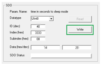
Figure 1: CANopen SDO -
Check that the device is set to sleep mode after the specified time is elapsed.
Power Management - Acceleration Sensor Wake-up Force
When the internal accelerometer detects an acceleration force higher than the configured value, the device automatically wakes up from sleep mode.
You can enable the Acceleration Sensor Wake-up Force as follows:
- Open the latest device configuration with the Proemion Configurator software.
- Add the device variable Power Management - Acceleration Sensor Wake-up Force to your configuration.
-
Write the acceleration force into the parameter value input field.
Note
The recommended threshold for the acceleration force is at least
1.2 g. Otherwise the device might get into a kind of restart cycle. -
Save the updated configuration file with a new Device Configuration Version String.
- Write the updated configuration to the device.
- Perform a reset of the device.
- Check if the new power management settings are applied correctly.
Power Management - Cyclic Wake-up Time
When in sleep mode, the device will wake up from sleep mode automatically after the configured time period.
You can enable the Power Management - Cyclic Wake-up Time as follows:
- Open the latest device configuration with the Proemion Configurator software.
- Add the device variable Power Management - Cyclic Wake-up Time to your configuration
-
Write the desired time for the cyclic wake-up in seconds into the parameter value input field.
Note
The minimum possible value for the cyclic wake-up time is
120 seconds. Lower values should not be used. -
Save the updated configuration file with a new Device Configuration Version String.
- Write the updated configuration to the device.
- Perform a reset of the device
- Check if the new power management settings are applied correctly.
Power Management - Deep Sleep Flag
The use of Power Management - Deep Sleep Flag is especially recommended for devices with internal battery and additional wake up flags configured. This function was implemented to avoid that the device wakes up during storage time and transport and hence the battery gets discharged.
Note
With deep sleep mode enabled, the device will ignore the configured wakeup flags such as cyclic wake up or acceleration force.
Note
Power Management - Deep Sleep Flag is a volatile device variable and therefore considered as a one-time function.
Wake up of the device is possible when at least one of the following condition is fulfilled:
- Rising edge on IO - Terminal30 Voltage.
- The IO - Terminal 15(Ignition) State is at level
high(> 6 V) - A CAN message is present at the CAN1 or CAN 3 interface
You can set the device into deep sleep mode before transport as follows:
- Open the latest device configuration with the Proemion Configurator software.
- Add the device variable Power Management – Deep Sleep Flag to your configuration.
- Write the value 0x01 into the parameter value input field of the device variable Power Management – Deep SleepFlag to enable the deep sleep mode
- Add the device variable Power Management – Time to Sleep to your configuration.
- Define a value for the countdown time in seconds to sleep mode in the parameter value input field.
- Ensure that there are no CAN messages left on the CAN bus.
- Ensure that the terminal 15 is at level low.
- Write the updated configuration to the device.
- Wait for the specified time until the device is set to deep sleep mode.
- Verify that the device does not wake up by the configured wake-up flags such as acceleration force or cyclic wake-up time.
RealTime Operation
The Online Mode covers both the transmission close to RealTime and Logging of CAN messages and data, see chapter Online Mode.
Use the Remote Service Tool software to create a RealTime connection and evaluate CAN messages. For configuration details, refer to the Remote Service Tool Manual.
Logging
Logging
The Online Mode covers both the transmission close to RealTime and Logging of CAN messages and data, see chapter Online Mode.
The colored dot in the Machines Overview indicates the status:
- Grey – device is offline.
- Green – device is online and it is logging data.
- Blue – device is online and it transmits RealTime data.
The device logs CAN messages, GNSS data, and internal variables.
All the recorded data is saved in an internal, nonvolatile memory and automatically sent to the DataPlatform when a connection is available.
Note
The internal nonvolatile memory also stores recorded data as *.CLF-files. The maximum number of files which can be stored on the internal memory is 4000 files with a file size up to 1 KB. When the total of 4000 files is reached, newly saved files will overwrite the oldest file.
Configuring variables for CAN communication
To enable CAN communication and data logging, you must configure the following variables.
CAN Settings
The variables required concern the CAN connection and belong to the object dictionary group DEVICE VARIABLES.
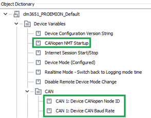
| Variable | Value | Function |
|---|---|---|
| CANOPEN NMT STARTUP | 0 |
Automatically sets the device to CANopen mode "Operational". |
| CAN1/CAN2/CAN3:DEVICE CANOPEN NODE-ID | 1 … 127 |
The CANopen node address (can_be_left_at_the_standard_value). |
| CAN1/CAN2/CAN3:DEVICE CAN BAUD RATE | min. 50 kbit/s; max. 1 Mbit/s (default: 250kBit/s) | The baud rate at which the CAN bus operates. |
Logging Variables
The variables required concern the logfile and belong to the DEVICE VARIABLES > LOGGING object dictionary group.
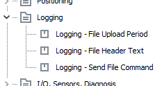
| Variable | Function |
|---|---|
| LOGGING -- FILE UPLOAD PERIOD | Period in which the logfile is completed and sent to the DataPlatform. value = 0 → data is sent when the size of the logfile reaches 1 kB. |
| LOGGING -- SEND FILE COMMAND | Assign any value to the variable during operation in order to immediately close and transfer the existing logfile. |
To track which device configuration was used to log the data, use the Device Configuration Version String device variable (part of DEVICE VARIABLES, not the LOGGING object dictionary group). Its value is written to every logfile. For more information, see DOD Versioning.
Logging Mode Examples
CAN logging Example 1 - Cyclic logging
In the following, the example of a J1939 message is used to explain the general procedure for configuring CAN reception messages. The procedure can also be applied to other CAN messages from other CAN protocols. For detailed information on creating objects, see Creating Object Dictionary Groups and Objects.
CREATING A PGN 61444
-
Create the object dictionary group CUSTOM CAN COMMUNICATION > RECEIVE CAN MESSAGES (PDOS) .
-
Create the RECEIVE MESSAGE PDO object in the RECEIVE CAN MESSAGES (PDOS) object dictionary group you have created.
-
Rename the RECEIVE MESSAGE PDO object to PGN 61444.
RECEIVE MESSAGE COMMUNICATION PARAMETERS
-
Select the COMMUNICATION tab
-
Make the following settings.
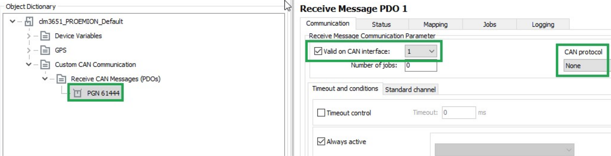
Description Selection Function VALID ON CAN INTERFACE Set Enabling the configuration, defining the CAN interface for reception (if_several_are_available). CAN PROTOCOL None The received CAN message is a single message (Layer_2). It is not treated according to a superordinate CAN protocol.
TIMEOUT AND CONDITIONS
Select the TIMEOUT AND CONDITIONS tab.
Make the following settings.
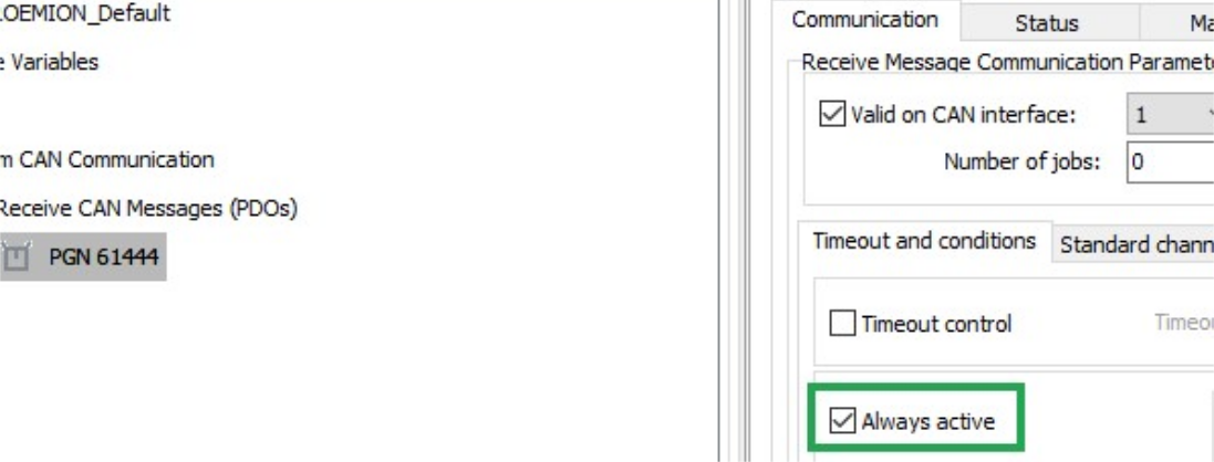
| Description | Selection | Function |
|---|---|---|
| ALWAYS ACTIVE | Set | The CAN message is received irrespective of events or conditions. |
STANDARD CHANNEL
Select the STANDARD CHANNEL tab.
Make the following settings.
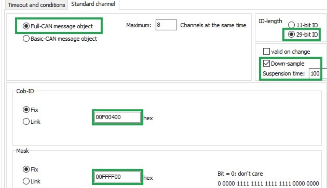
| Description | Selection | Function |
|---|---|---|
| FULL CAN MESSAGE OBJECT | Set | Assigns the receive message to a controller channel. |
| ID-LENGTH | 29-bit ID | ID length of the CAN message to be received. |
| DOWN-SAMPLE | Set | Receive message max. every 100 ms. |
| COB-ID | Fix (00F00400) |
Fixed identifier of the receive message (J1939_PGN_61444). |
| MASK | Fix (00FFFF00) |
Determines that bits 8 ... 24 of the identifier fixed in COB-ID must not vary in the identifier of the received message. In the J1939 protocol, the first bits of the identifier define the priority and the last bits of the identifier define the source address. These are ignored when the message is received. |
LOG ALL DATA BYTES EVERY 60 SECONDS
In this example, all data bytes are simply logged cyclically every 60 seconds. There are no additional conditions, and the data bytes are not checked.
LOGGING - CONDITIONS
Define the following settings for the PGN 61444 object.
Select the LOGGING tab.
Select the CONDITIONS tab.
Make the following settings.
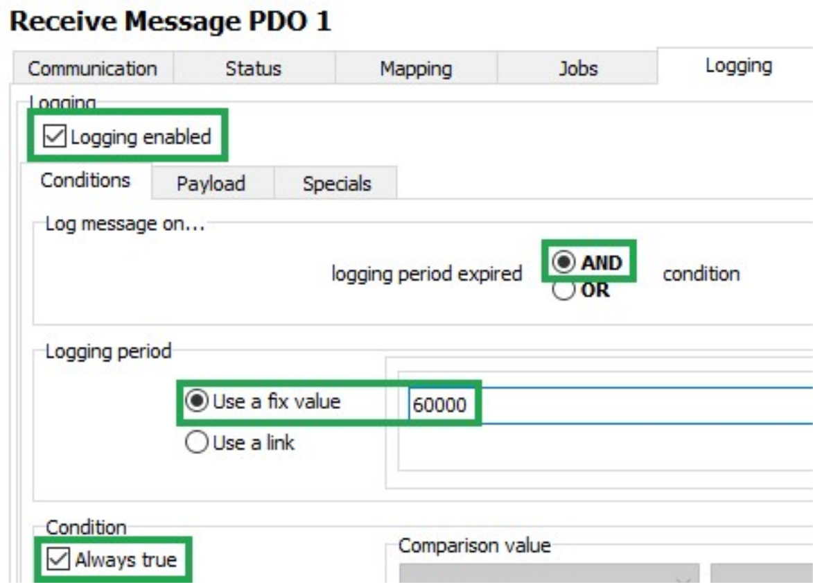
| Description | Selection | Function |
|---|---|---|
| LOGGING ENABLED | Set | Logging enabled |
| LOG MESSAGE ON | AND | The data is only logged when timeout is reached AND the condition is met. |
| LOGGING PERIOD | Use a fixed value (60000) |
Duration of the logging interval in milliseconds. |
| CONDITION / ALWAYS TRUE | Set | Logging takes place without prior checking of conditions. |
Payload
Select the PAYLOAD tab.
Make the following settings.
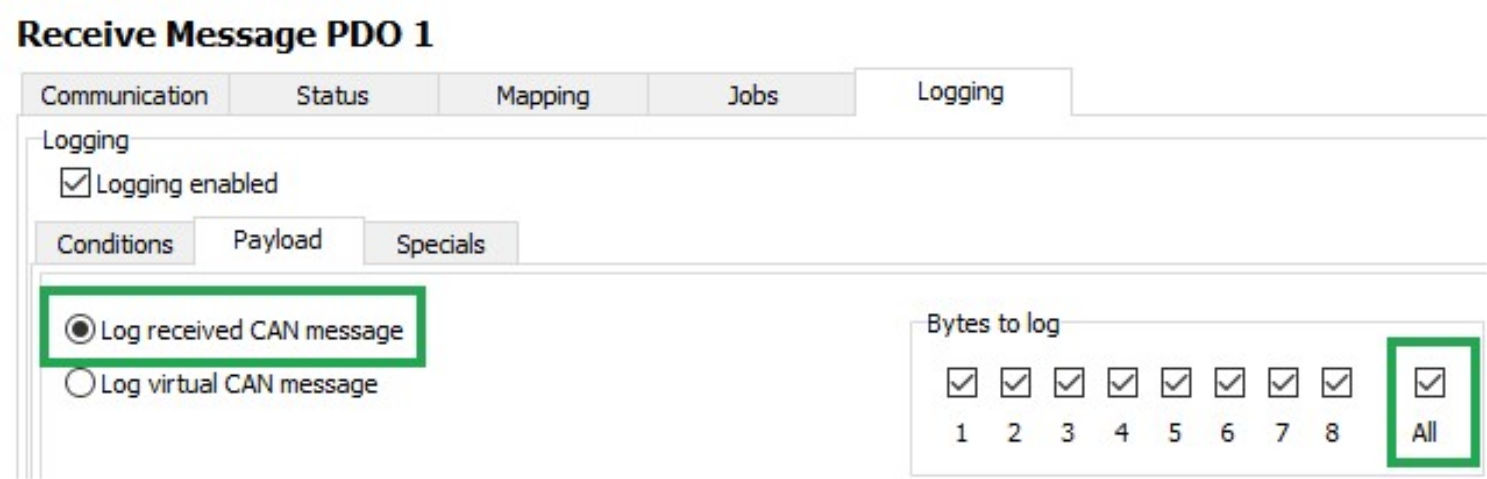
| Description | Selection | Function |
|---|---|---|
| LOG RECEIVED CAN MESSAGE | Set | Log data of the receive CAN message. |
| BYTES TO LOG | All | Log all data bytes. |
Click on the SAVE button.
Load the configuration to the device.
✓ You have completed the configuration for logging of all data bytes of the J1939 PGN 61444 every 60 seconds.
CAN logging Example 2 -- Logging specific data bytes under certain conditions
In this example, specific data bytes are logged under defined conditions.
Data bytes 2 ... 5 and 8 of the CAN messages received are logged when the engine speed (data_bytes_4_and_5) changes by ± 500 rpm, or every 10 minutes.
A received CAN message is processed with the following functions:
-
Mapping
-
Jobs
-
Logging
VARIABLES
If you want to log data under defined conditions, you need certain variables for checking values.
These variables belong to the INTERFACE VARIABLES object dictionary group.
Create the INTERFACE VARIABLES object dictionary group.
In the INTERFACE VARIABLES object dictionary group, create four new INTERFACE VARIABLE objects.
✓ The LIST OF INTERFACE VARIABLES window opens.
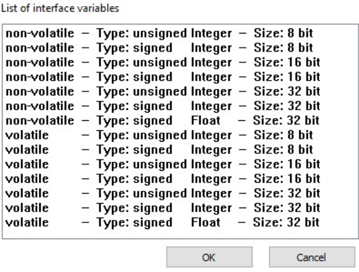
Select the first INTERFACE VARIABLE object according to the following table.
| Designation | Type | Sign | Size |
|---|---|---|---|
| volatile U8 Trigger | volatile | unsigned | 8 bits |
| volatile S32 Engine Speed new | volatile | signed | 32 bits |
| volatile S32 Engine Speed old | volatile | signed | 32 bits |
| non-volatile U16 threshold value | non-volatile | unsigned | 16 bits |
Click on the OK button.
✓ The INTERFACE VARIABLE object with the selected settings is created.
Repeat this procedure for the other three INTERFACE VARIABLE objects.
Rename the four INTERFACE VARIABLE objects according to the table.
Define a threshold value for the NON-VOLATILE U16 THRESHOLD VALUE object.
✓ The four INTERFACE VARIABLE objects are displayed
LOGGING - CONDITIONS
Define the following settings for the PGN 61444 object.
Select the LOGGING tab.
Select the CONDITIONS tab.
Make the following settings.
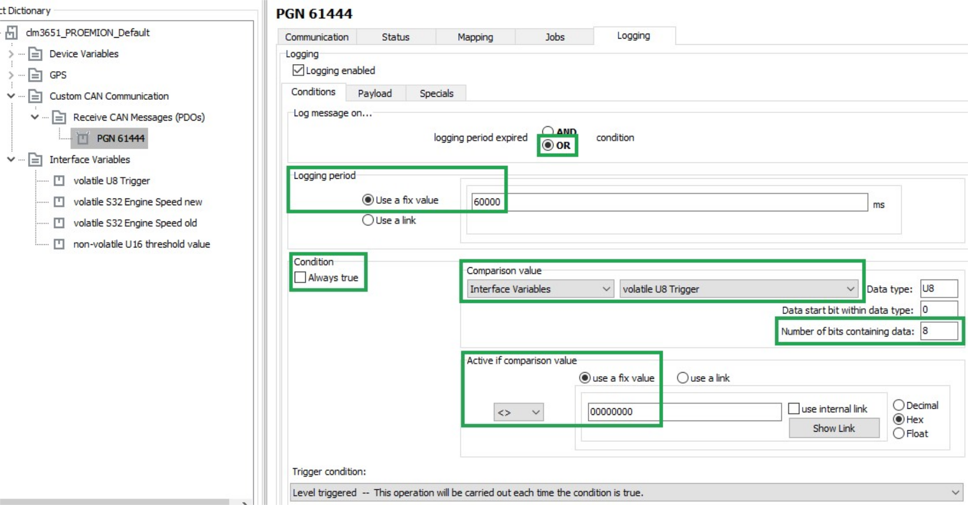
| Description | Selection | Function |
|---|---|---|
| LOG MESSAGE ON | OR |
The data is logged when timeout is reached OR the condition is met. |
| LOGGING PERIOD | Use a fixed value (600000) |
Duration of the logging interval in milliseconds. |
| CONDITION / ALWAYS TRUE | not set | The data is logged depending on the result of the check. |
| COMPARISON VALUE | volatile U8 Trigger |
Logging depends on the VOLATILE U8 TRIGGER variable. |
| NUMBER OF BITS CONTAINING DATA | 08 |
All 8 bits of the variable are compared with COMPARISON VALUE. |
| ACTIVE IF COMPARISON VALUE | <>0 |
Data is only logged if the variable VOLATILE U8 TRIGGER is not equal to 0. |
| TRIGGER CONDITION | Level triggered - This operation will be carried out each time the condition is true. | Logging is enabled as long as the variable VOLATILE U8 TRIGGER is not equal to 0. |
PAYLOAD
Select the PAYLOAD tab.
Define the following settings.
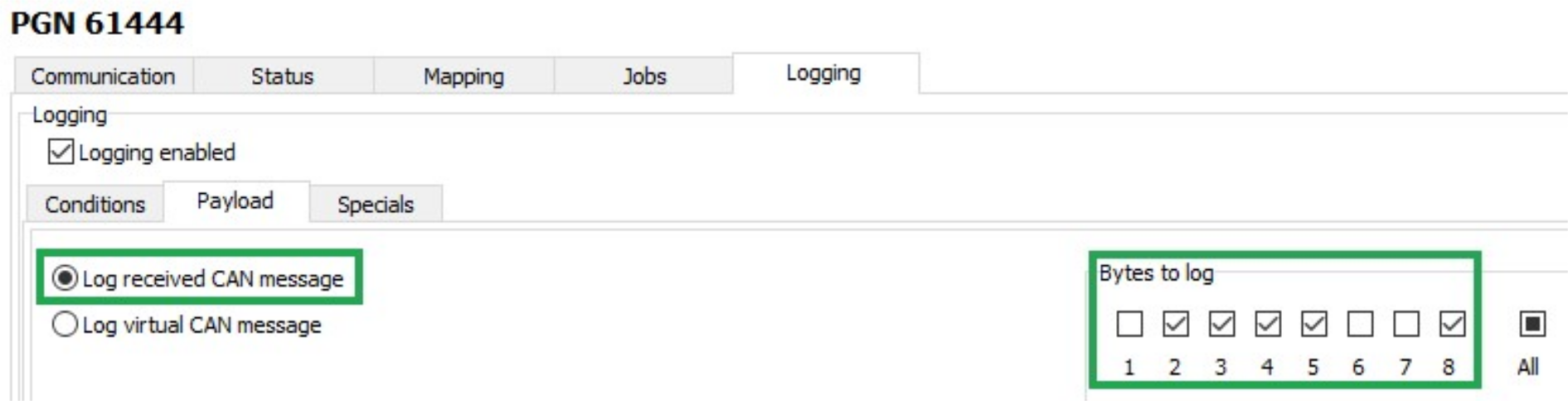
| Description | Selection | Function |
|---|---|---|
| LOG RECEIVED CAN MESSAGE | Set | Log data of the receive CAN message. |
| BYTES TO LOG | 2 ... 5 and 8 | Logging selected data bytes |
MAPPING - ACTIVE CONDITION
During mapping, data is copied from the CAN message to variables. You can then process the copied data in the device and perform calculations.
Select the MAPPING tab.
Select the ACTIVE CONDITION tab.
Define the following settings.
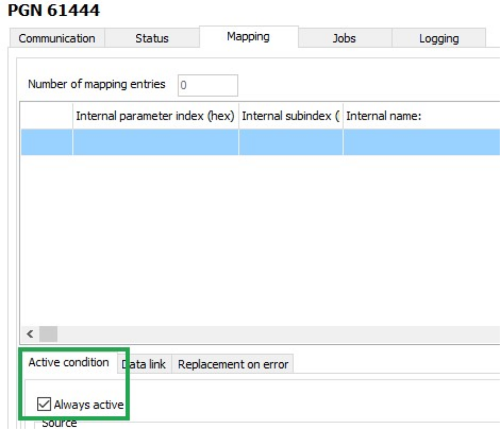
| Description | Selection | Function |
|---|---|---|
| ALWAYS ACTIVE | Set | Mapping always takes place without conditions. |
DATA LINK
Select the DATA LINK tab.
Define the following settings.
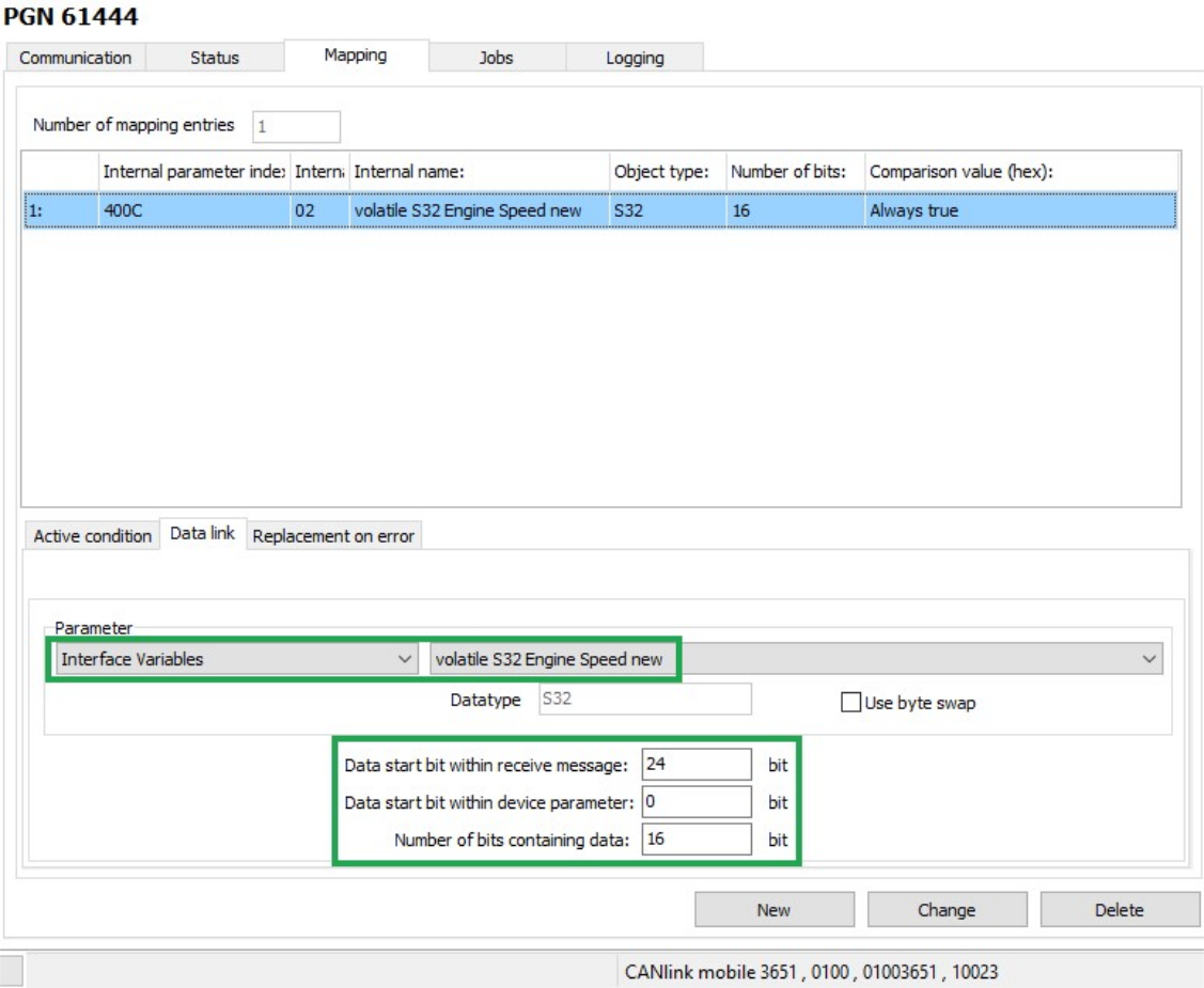
| Description | Selection | Function |
|---|---|---|
| PARAMETER | volatile S32 Engine Speed new | The data is written to the VOLATILE S32 ENGINE SPEED NEW variable. |
| DATA START BIT WITHIN RECEIVE MESSAGE | 24 bits | The data used starts with bit 24 (from_the_4th_byte). |
| DATA START BIT WITHIN DEVICE PARAMETER | 0 bits | The data used begins from bit 0 |
| NUMBER OF BITS CONTAINING DATA | 16 bits | The data used has 16 bits (2_bytes). |
Click on the NEW button to create the mapping entry.
✓ The mapping entry is adopted in the table.
✓ The data is copied into the internal variable on reception of a CAN message.
JOBS
Every time a CAN message is received, jobs are performed after mapping and before logging.
In the JOBS tab, configure the calculation operations you need for your job.
For the example configuration, you need two jobs with the function CALCULATE PARAMETER VALUE FUNCTION. With this function, you perform calculation operations and overwrite interface variables with calculated values.
JOB 1
With the first job, you check whether the current speed is above or below the threshold value. If one of these two cases applies, the VOLATILE U8 TRIGGER variable should be set to the value 1. This triggers logging of the CAN message.
| Variable | Type | Name/value |
|---|---|---|
| A | S32 | volatile S32 Engine Speed new |
| B | S32 | volatile S32 Engine Speed old |
| C | U16 | non-volatile U16 threshold value |
| D | S32 | volatile S32 Engine Speed new |
| E | S32 | volatile S32 Engine Speed old |
| F | U16 | non-volatile U16 threshold value |
The buttons for entering the calculation operations have the following functions:
| Buttons | Description |
|---|---|
 |
C = Clear: Deletes the entire calculation operation |
CE = Clear Entry: Only deletes the last symbol entered |
|
 |
Add variables to the calculation operation.Click on the button to open a window. Assign fixed values, interface variables or device variables to the variables. After you have defined a variable, the display on the button switches to the next variable. The selected variables are listed under LIST OF OPERANDS, including their values and types. |
 |
Basic calculation types (addition, subtraction, multiplication, division) |
   |
NOTE: Before applying these operations any input value is cast to unsigned integer type! |
and = arithmetic (bitwise) AND operation. |
|
or = arithmetic (bitwise) OR operation. |
|
xor = arithmetic (bitwise) XOR operation. |
|
| On integer numbers, the operation is performed bitwise. If the operators only contain the values 0 or 1, the operation can be considered a logical calculation. | |
not = logical NOT operation. |
|
| If the operand is 0, the expression evaluates to 1. If the operand is unequal to 0, the expression evaluates to 0. | |
| WARNING: Do not apply these operators on floating-point numbers! | |
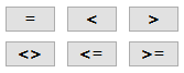 |
Comparative value (equal_to, less_than, greater_than, not_equal_to, less_or_equal_to, and_greater_or_equal_to). The expression evaluates to 1 when the comparison is true. The expression evaluates to 0 when the comparison is not false. |
 |
Brackets |
Note
The calculation formulas are evaluated from left to right. Mathematical priority rules are not observed!
Define the priority calculations in the formula using brackets
JOB 2
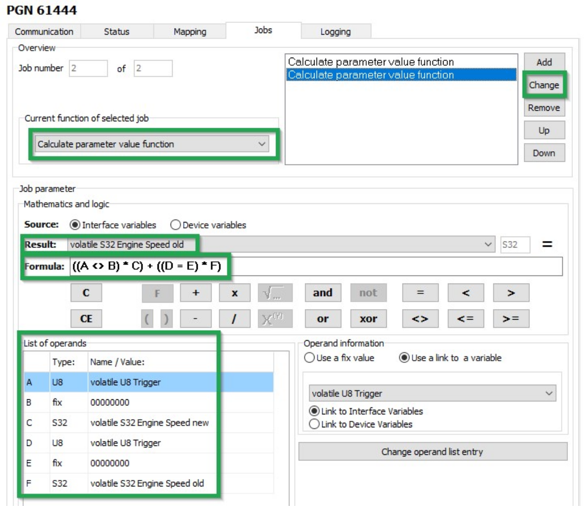
In the second job, you replace the value of the VOLATILE S32 ENGINE SPEED OLD variable with the value of the VOLATILE S32 ENGINE SPEED NEW variable as soon as the VOLATILE U8 TRIGGER variable has the value 1. This updates the speed from which the deviation should be detected.
This updates the speed from which the deviation should be detected.
-
Select the JOBS tab.
-
In the CURRENT FUNCTION OF SELECTED JOB list, select the function CALCULATE PARAMETER VALUE FUNCTION.
-
In the RESULT list, select the trigger VOLATILE S32 ENGINE SPEED OLD.
-
Using the buttons in the MATHEMATICS AND LOGIC section, enter the calculation operations
((A <>_B) * C) + ((D # E) * F). -
Click on button A.
!!! note If you click on a placeholder (e.g. A), the window INPUT OPERAND INFORMATION OR OPEN A NEW OPERATION opens. You can find the allocation of the variables for this example in the table below.
-
Click on the variable in the list that you want to allocate the placeholder to.
-
Allocate the following variables to the placeholders:
Variable Type Name/value A U8 volatile U8 Trigger B fix 00000000C S32 volatile S32 Engine Speed new D U8 volatile U8 Trigger E fix 00000000F S32 volatile S32 Engine Speed old : Variables - Job 2 -
Click on the NEW button when you have entered the calculation operations completely.
-
Click on FILE > SAVE in the menu.
-
Load the configuration to the device. See Chapter Loading the configuration to the device.
✓ You have completed the configuration for logging specific data bytes.
CAN logging Example 3 - On Change Logging
On receipt of CAN messages whose content seldom changes, you can activate the VALID ON CHANGE option.
If the option is activated, a CAN message received is only recorded by the device if a value within the data bytes has changed.
This option can be activated for standard 11-bit and 29-bit CAN messages as well as for J1939 CAN messages.
High data volume
If the VALID ON CHANGE option is activated, the DOWN-SAMPLE option is automatically deactivated and no longer limits the frequency of recording. Each CAN message received with a modified content will be recorded by the device. This leads to high data volumes in the case of CAN messages whose content changes in the millisecond range.
- Only activate the VALID ON CHANGE option for carefully selected messages.
-
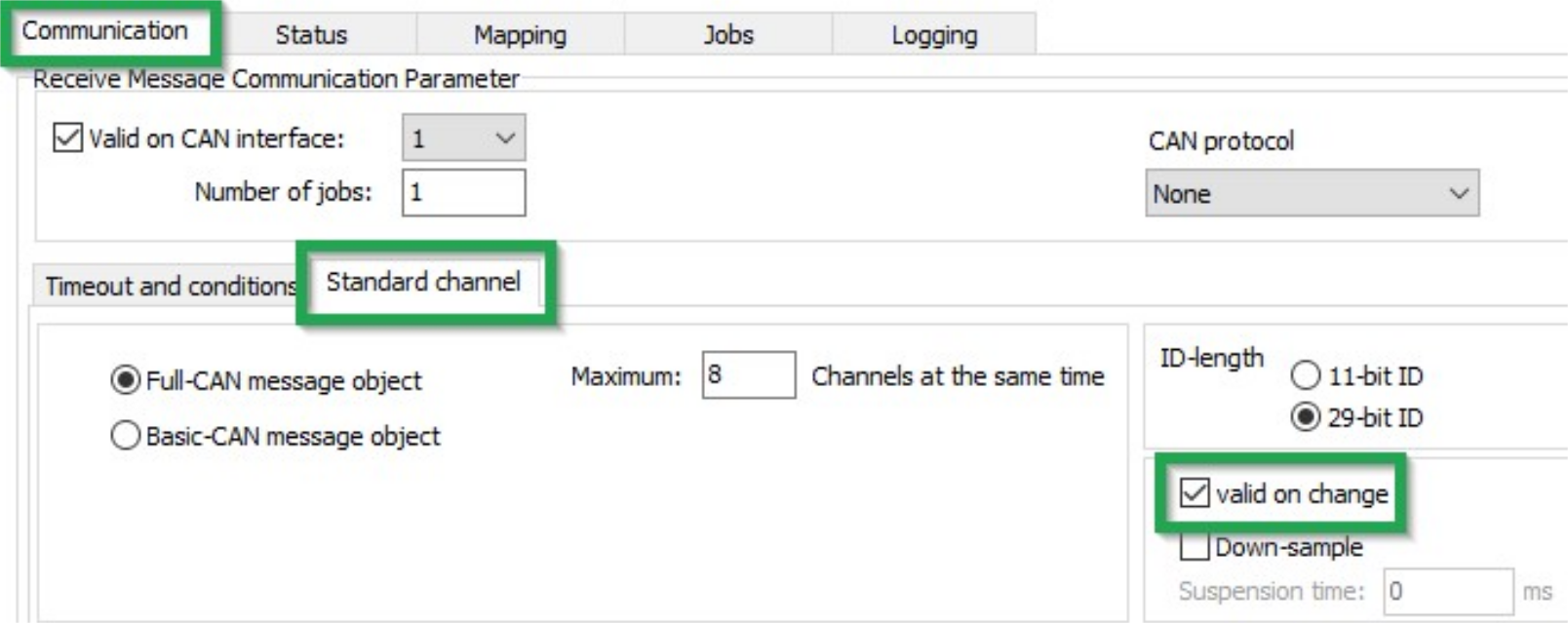
Navigate to the COMMUNICATION section.
-
Move to the STANDARD CHANNEL section and click to enable the VALID ON CHANGE option.
-
Navigate to the LOGGING section.
-
Move to the LOGGING section and click to tick the LOGGING ENABLED option.
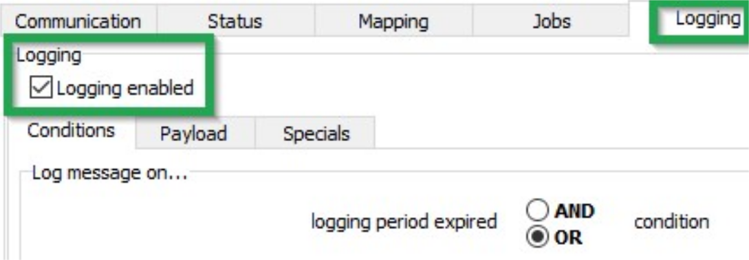
✓ CAN messages received with a modified content are recorded.
Logging GNSS position data
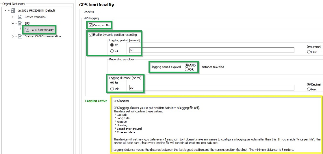
The GNSS position data contains information on longitude and latitude, altitude and direction as well as speed, time and date.
Data is only logged when valid position data is received.
Define the following settings:
| Variable | Function |
|---|---|
| ONCE PER FILE | Each logfile contains position data at least once. |
| ENABLE DYNAMIC POSITION RECORDING | Enables/ Disables the position data logging. |
| LOGGING PERIOD (SEC) | Time period during which the position data should be logged. |
| AND / OR | AND: Position data is logged if both conditions (time_and_distance) are met. |
OR: Position data is logged if one of the conditions (time_or_distance) is met. |
|
| LOGGING DISTANCE (METERS) | Distance between the last position logged and the current position (linear_distance). |
Oversampling due to too-frequent logging of GNSS position data.
High data consumption or high number of write cycles into the internal memory.
At the following settings, the position data is logged every 100 ms: Logging period = 0 Logging distance = 0 These settings generate a high data consumption. If there is no Cellular connection, the position data is written to the device’s internal memory instead. This considerably reduces the service life of the internal memory.
- Under Variable Logging period, enter a value >= 1 second because the device only receives new GNSS data every 1 second.
- Under Variable Logging distance, enter a value above the GNSS accuracy
Configuring the logging of internal variables
You can log various internal variables. Internal variables can be both device variables and interface variables.
To log internal variables, you need an ACTION - FUNCTION - OPERATION object in the OPERATION MANAGER object dictionary group. With the object ACTION - FUNCTION - OPERATION, up to 32 internal variables can be logged in one process as a virtual CAN message.
-
Start the Proemion Configurator software.
-
Choose FILE > OPEN from the menu.
-
Open the desired configuration file.
-
Create an OPERATION MANAGER object dictionary group.
-
Create an ACTION - FUNCTION - OPERATION 1 object in the OPERATION MANAGER object dictionary group.
-
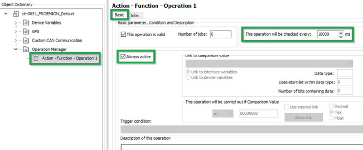
Select the BASIC tab.
-
Enter a value in milliseconds in the THIS OPERATION WILL BE CHECKED EVERY field. This value determines the intervals at which the variables are logged.
-
Check the ALWAYS ACTIVE box. Logging takes place irrespective of conditions. Alternatively, you can define conditions for logging.
-
Click on the SAVE button.
-
Select the JOBS tab.

-
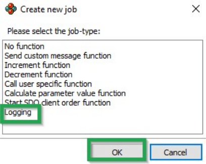
In the OVERVIEW field, click on the ADD button.
✓ The CREATE NEW JOB window opens.
-
Select the LOGGING job type.
-
Click on the OK button.
-
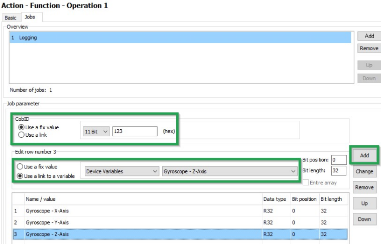
In the COBID field, enter the ID (hex) for the virtual CAN message. The ID must not be used by other CAN messages.
-
In the ADD NEW ROW field, select the variable type and the variable.
-
In the JOB PARAMETER field, click on the ADD button.
-
Add further variables if required.
-
Click on FILE > SAVE in the menu.
✓ You have completed the configuration for logging of internal variables.
Evaluating the data logged on the DataPlatform
WRITING A PARSING CONFIGURATION FILE (PDC) AND ASSIGNING IT TO A MACHINE
In order to be able to evaluate the logged messages and display the signals on the DataPlatform, you must create an additional configuration file (PDC file) and assign it to the device on the DataPlatform.
Note
A detailed description on how to create a PDC file, can be found at the PDC Manual.
J1939 DM1 logging
In the following, it is described how to configure the DM1 logging in the Proemion Configurator.
It is possible to configure the logging of more than one source address. For a detailed description of J1939 DM1, read J1939 DM1 DM2.
Open the .DOD file in the Proemion Configurator and select the desired "Receive Message (PDO)" within the Object Dictionary on the left hand-side. For the following example, the source address 0x003 is used.
In the Communication tab, proceed as follows:
-
Change CAN protocol to "J1939".
-
Fill in the PGN with "FECA".
-
Source Address is in this example "03".
-
Source Address Value is selected with "Fix".
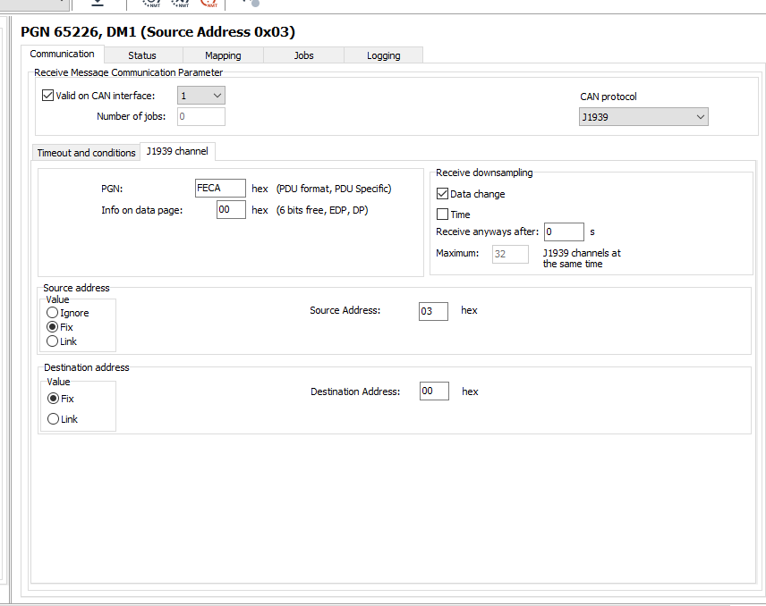
Figure 1: Communication tab - Example Source Address 0x03
In the Logging tab, proceed as follows:
-
Activate the check box Logging enabled.
-
Select the AND condition for logging period expired.
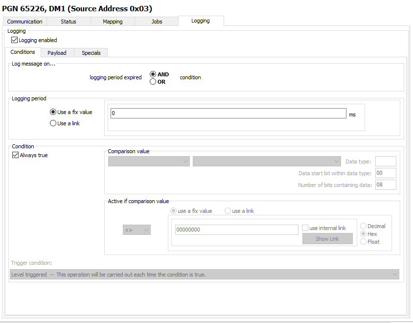
Figure 2: Logging tab
Data Transfer
File Transfer
You can use the device to transfer files between the DataPlatform and the machine's CAN open network.
Transfer User File via the DataPlatform
Performing controller updates without being physically on-site is an increasingly important application for many OEMs. This chapter describes how a user file can be transferred from the Proemion DataPlatform via internet and cellular network to a CANlink® mobile and from there to an ECU via CAN Bus.
A common use case for this function could be a parameter update of the ECU.
The update file is loaded remotely into the CANlink® mobile and stored within the internal filesystem.
An external device can then download the file by using SDO commands on the CAN bus. The CANlink® mobile only acts as a gateway with an integrated CANopen file server.
Please be aware that the transferred files are not checked or controlled in any way by the CANlink® mobile itself.
So, the files must be checked and processed by the target device (ECU).
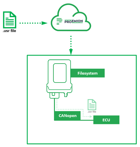
Required file properties
As the files are neither handled or checked by the Proemion DataPlatform nor by the CANlink® mobile, any file format and file content can be transferred. But independent of the user file format and content, the files must adhere to the following rules:
- The file name must consist of eight letters or digits.
- The file extension must be
*.usr. - The file size must be a maximum of 50 MB.
Example of a valid file name: Update01.usr
Upload the File from the DataPlatform to the CANlink® mobile
- Please make sure that your DataPortal user has the permission set
machine–adminassigned. - Login to your Proemion DataPortal Account.
- Go to > Administration > Transfers (1).
- Click on UPLOAD FILE (2).
- Select the desired machine (3).
- Select the desired
*.usrfile for upload (4). - Click on UPLOAD (5).
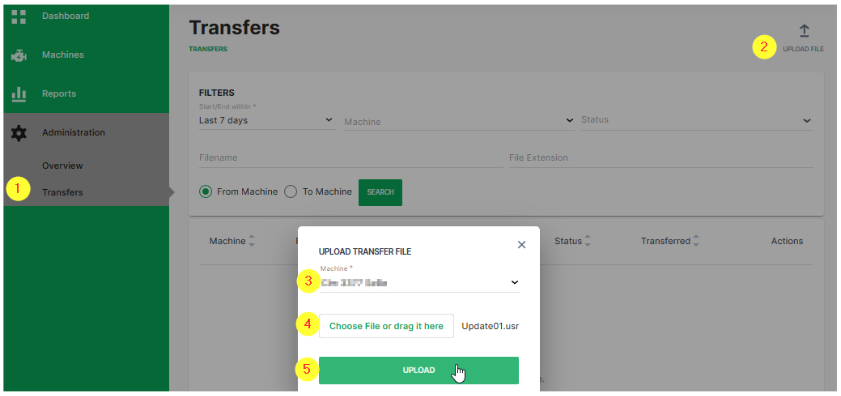
✓ The uploaded file will appear in the file transfer list after successful upload.
✓ The DataPlatform manages the file transfer to the selected machine (CANlink® mobile) automatically as soon as the device is ready to receive the file.
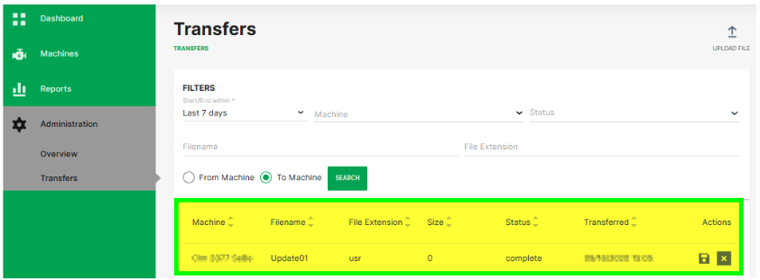
Note
In case that a file transfer directly via the REST API is required, please refer to the instructions at the DataPlatform API docs REST API.
Transfer the file from the CANlink® mobile to the ECU via CAN
The CANlink® mobile has an internal file system that can be accessed by CANopen SDO commands. The protocol for the file handling communication on CAN Bus is CANopen. SDO requests and the SDO block transfer protocol are used to exchange commands and payload.
Note
Further information on file transfer can be found in CANopen File Server.
- As indication that a new file had been received by the CANlink® mobile, the device variable with object index
0x5402subindex0x01is automatically set to0x01. Herewith any ECU on the CAN network can poll the status of this device variable to monitor the reception of new files. - In the next step the ECU must check the name of the available files which were uploaded to the CANlink® mobile. This is done by writing the command string
lsinto device variable with object index0x4444subindex0x01. - Check the status of this command. Read out the device variable with object index
0x4444subindex0x03. The status should be3(=LIST). - Read out the content of device variable with object index
0x4444subindex0x02. This will give you the exact file name. - The download of the specific file to the ECU can be triggered by writing the command string
rd “[file_name]”into device variable with object index0x4444subindex0x01. - Check the status of this command. Read out the device variable with object index
0x4444subindex0x03. The status should be2(=READ). - To download the file content, read out the domain of device variable with object index
0x4444subindex0x02. - Once the downloaded file has been processed successfully at the ECU, it should be deleted in the CANlink® mobile by writing the command string
del “[file_name]”into the device variable with object index0x4444subindex0x01. - To enable the download of a new file, the device variable with object index
0x5402, Sub Index0x01must be set to0x00.
Note
The maximum file size is limited by the built-in flash memory of the CANlink® mobile.
It must be ensured that there is minimum of 8 Mbyte of free memory available for logging and other internal device processes.
The free memory is to be checked by reading out the device variable with object index 0x4444 subindex 0x04.
Generic File Transfer
Transferring a File to the DataPlatform
A simple transfer of files up to 128k Byte via the CAN bus to the DataPlatform is implemented in the device. The files are saved in the device in an internal nonvolatile memory and automatically transferred to the DataPlatform when a server link is established.
The following steps are required for the transfer:
-
An external device transfers a file using the CANopen SDO protocol to the object index
0x5421subindex0x03of the CANlink® mobile: DEVICE VARIABLES > FILE TRANSFER TRANSMIT - FILE DATA - CACHED MODE -
An external device transfers the file name using the CANopen SDO protocol to the object index
0x5420subindex0x03of the CANlink® mobile as a string in the format 8.3 (see File Transfer Restrictions: DEVICE VARIABLES > FILE TRANSFER TRANSMIT - FILENAME - CACHED MODE -
An external device writes the value 1 to the object index
0x5422subindex0x03of the CANlink® mobile which triggers automatic file transfer to the DataPlatform: DEVICE VARIABLES > FILE TRANSFER TRANSMIT - COMMAND - CACHED MODE
You can find out the current free memory space available using the object index 0x5423 subindex 0x04 (DEVICE VARIABLES > FILE TRANSFER TRANSMIT - GET FREE SPACE - CACHED MODE). If memory space is available, several files can be logged in the device. The files are then automatically transmitted to the DataPlatform in the order in which they were written to the device.
For detailed information on creating objects, see Creating Object Dictionary Groups and Objects.
Reading a File Transferred by the DataPlatform
The DataPlatform can transfer files in segments of 1024 bytes each via the device. Files larger than 1024 bytes are transferred in segments the receiving ECU needs to concatenate again.
Note
This applies to all files except files with the ending .usr.
.usr files are received completely and only provided to the ECU after complete reception.
For more information, read Transfer User File via the DataPlatform.
The files transferred by the DataPlatform are saved to the device in an internal volatile memory and can be read out of the device via the CANopen protocol.
Proceed as follows to be able to read out files transferred from the DataPlatform.
1) Check object for file (segment).
- For all files except
.usr, check that the object index0x5402:0x00has a value <>0.
This value indicates that a file segment has been received by the device from DataPlatform and is available. Other values are:
0x00: no file segment available0x01: file segment available0x81: last file segment available
Object name: FILE TRANSFER RECEIVE - INDICATION
Note
The object index 0x5403 subindex 0x00 contains the total number of segments for the current file.
Object name: FILE TRANSFER RECEIVE - NUMBER OF FILE ELEMENTS
The object index 0x5404 subindex 0x00 contains the number of the currently received file segment.
Object name: FILE TRANSFER RECEIVE - ACTUAL FILE ELEMENT
2) Read file name.
If the object index 0x5402 subindex 0x00 indicates a file segment is available, you can read the file name from the object index 0x5400 subindex 0x00.
Object name: FILE TRANSFER RECEIVE - FILENAME
3) Read off file.
Read off the file from the object index 0x5401 subindex 0x00.
Object name: FILE TRANSFER RECEIVE - FILE
4) Write object.
When the file has been read out, write the value 0x00 to the object index 0x5402 subindex 0x00.
Object name: FILE TRANSFER RECEIVE - INDICATION
5) Receive next files.
- In order to receive the next file segment after a file segment was received, in the object index
0x5402subindex0x00the value0x01must be set to0. - In order to receive the next file after a file was received completely, in the object index
0x5402subindex0x00the value0x81must be set to0.
✓ The device is then ready to receive a new file segment from the DataPlatform.
For detailed information on creating objects, see Creating Object Dictionary Groups and Objects.
File Transfer Restrictions
Restrictions apply to file transfer. The following conditions must be met:
-
The file names must have 8 characters and the file extension must have 3 characters (8.3 format).
-
Characters permitted for the file name and file extension are :
"A", ... "Z","a", ... "z"and"0", ... "9" -
The following file extensions are reserved for internal use only and may not be used for customer application:
.obr,.obw,.obc,.dbs,.prg,.bin,.clf,.msg
If these conditions are not met, the file will be rejected by the device and/or DataPlatform. This blocks transmission in both directions. To clear the blockage, you must delete the faulty file from the DataPlatform or from the file transfer.
Further information on how to delete faulty files from the DataPlatform can be found here: File Transfer
CANopen File Server
The CANlink mobile offers a local nonvolatile file storage that can be accessed by CANopen SDO. This functionality for example is used for providing ECU update files to the machine received from the DataPlatform. Please also refer to Transfer User File via the DataPlatform.
The following functions are available for data access via the SDO:
| Function Code | Option | Description |
|---|---|---|
wr |
["]path name ["] |
Write in file (always_in_Append_mode) |
del |
["]path name["] |
Delete file or directory |
rd |
["]path name["] [-o n] [-l m] |
Read out of file |
ls |
List file or directory | |
cd |
[["]path["]] [..] [] |
Change directory |
The following functions are available following data access via CANopen:
| Index | Subindex | Meaning | Data Type | Description |
|---|---|---|---|---|
0x4444 |
0x01 |
Command | String |
See function descriptions. Please be aware that the maximum accessible file path size is 253 characters. |
0x4444 |
0x02 |
Data | Domain |
See function descriptions |
0x4444 |
0x03 |
Status | U16 |
The following states are displayed: 0 = OK / IDLE 1 = WRITE 2 = READ 3 = LIST 65535= ERROR |
0x4444 |
0x04 |
Available size | U32 |
Memory space available on file system in bytes |
0x4444 |
0x05 |
File size | U32 |
Size of current file selected, in bytes |
0x5402 |
0x01 |
Status | U16 |
The following states are displayed: 0 = *.usr-file not completely available 1 = *.usr-file completely available |
Note
The SDO client must wait until the file system status flag 0x4444 sub 0x03 reads 0x0000 - OK / IDLE after sending the delete file command before issuing any other SDO communication.
- The device may not respond to the SDO requests while it’s deleting the file and thus generate an SDO timeout also for reading the file system status flag.
- Do not issue any other SDO communication requests until the status reads OK / IDLE
Restrictions
Restrictions on the flash size and file storage using the file server.
Note
File or path names that contain a space must be placed in quotation marks.
Note
The available flash size for file storage is maximum of ~80 MB.
Folder or file names should consist of the following characters:
letters(uppercase/lowercase)numbers␣(space)_(underscore)-(hyphen)
For file names, a dot . is also accepted. However, it is also possible to create file names without a dot ..
Note
If a given path name starts with \, the path is considered as starting in the root folder.
In case that the path name does not start with \, the path is considered as starting within the current folder.
Note
Please be aware the filename ls.txt is reserved for the automatically generated listing file.
Function Description
The following sections describe the individual functions and structure of the respective commands.
When entering commands, pay attention to the correct spelling and notation.
If spaces are contained, the path and file input must be set in quotation marks. If no spaces are contained, the use of quotation marks is optional.
WR - Write
- Structure of the command:
wr "path\name"
If the wr command is written to the command object, the device checks whether a file with this name exists. If no file is available, a new one is created.
An error code appears in the status object if the file cannot be opened to be written to or an error occurs.
The current file size is displayed in the file size object. The data content can then be written in the data object.
After completing the write operation to the data object, the file is automatically closed and the command deleted.
Directories can also be created with this command.
Note
The wr command always works in append mode.
To overwrite an existing file, delete all old files manually beforehand.
Note
For the wr command, the following rules must be considered:
- When only creating a folder, the command must always end with
\. - If no
\is provided, a file is created without an extension. - If no
\and no.is provided, a file is created without an extension
DEL - Delete
- Structure of the command:
del "path\name"
If the del command is written to the command object, the device checks for existing files with this name. If the file exists, it will be deleted.
An error code appears in the status object if the file cannot be deleted or an error occurs.
When the process is completed, the command is deleted.
Directories can also be deleted in this way.
RD - Read File
- Structure of the command:
rd "path\name" [-o n] [-l m]
If the rd command is written to the command object, the device checks for existing files with this name.
An error code appears in the status object if the file does not exist or an error occurs.
The file size object displays the size of the current file. The data content can be read out of the data object.
After completing the read operation from the Data object, the file is automatically closed, and the command deleted.
The following options are available with this command:
-
-o n- Offset: n bytes The read process starts at the byte-position specified. Decimal or hexadecimal values are possible. -
-l m- Length: m bytes The number of bytes specified (maximum_till_the_end_of_the_file) is read out of the file. Decimal or hexadecimal values are possible. To specify hexadecimal value use the prefix0x, for example0xA.
Note
When using the rd command, it must be ensured that the order of the arguments is kept as shown in the example: rd "path\name" [-o n] [-l m].
LS - List file or directory
- Structure of the command:
ls
If the ls command is written to the command object, a file and directory list can be read out of the data object.
Directory names are identified by < and >. A line feed [CRLF] occurs after each entry.
When the read operation from the Data object is completed, the command is deleted.
The result of the ls command looks like this example:
Content of USER:
< . >
< .. >
ls.txt
< folder_name >
usrfile1.usr
usrfile2.usr
usrfile3.usr
CD - Change Directory
- Structure of the command:
cd ["path"], [..], []
If the cd command is written to the command object, the device checks whether a directory with this name exists. If a directory with this name exists, it is opened.
An error code appears in the status object if the directory does not exist or an error occurs.
When the process is completed, the command is deleted.
The following options are available with this command:
-
"path"- Change to the directory specified. -
..- Change to the directory level one level higher. -
\- Change to the root directory.
Updates
Safe Remote Updates Guideline
Introduction
Our firmware is subjected to an intensive testing process, including automated tests during development and dedicated testing for each final release candidate. This test suite is continuously expanded based on internal findings and field reports.
Despite these efforts, a residual risk of unexpected issues in specific scenarios remains.
To minimize this risk, we strongly recommend following the procedure outlined in this guideline when performing a remote firmware or configuration update campaign.
By adhering to these steps, you can significantly increase the safety and success rate of your update process.
Risk of Property Damage
It is strongly recommended not to remotely update all machines in a single step with a new configuration or firmware.
Remote Update Procedure
When planning a firmware or configuration roll-out, several steps should be considered to ensure the process is as safe and reliable as possible.
This guideline applies to each individual machine type or machine family. A machine family is defined by devices sharing the same configuration version, the same initial firmware, and — if applicable — the same SIM card settings.
Following these steps helps minimize the risk of update-related errors.
1. Initial Test on a Simulator or Sample Machine
Perform the first remote update on a simulator device whenever possible.
If a simulator is unavailable, use a single, easily accessible sample machine.
Verify that the update succeeds and that the device behaves as expected.
2. Update a Small Batch (Up to 10 Machines)
In the second step, extend the update to a maximum of 10 machines.
After completion, verify the success of the update on each machine individually.
3. Update a Partial Roll-out (Up to 15% of the Fleet)
If the second step is successful, proceed with a partial roll-out to a maximum of 15% of the fleet.
Conduct a success check after this roll-out as well.
4. Update the Remaining Fleet
Once all prior steps have been validated, roll out the update to the rest of the fleet.
Verifying Update Success
Between each roll-out step, perform sample checks to ensure that devices are operating as expected. Verification should include:
- Device startup and shutdown behavior in the machine environment
- Logged operational data
- File transfer to your ECU
- Execution of configured actions
- Any special or device-specific behaviors configured in your system
Configuration Update
You can use the Proemion Configurator to load a configuration update on the device. The configuration update can be loaded to the device via the CAN interface or the DataPlatform. The device identifies and automatically loads the new configuration.
Note
Changes with an write-access to any object that changes the device configuration, will put the device automatically into pre-operational mode.
This happens to prevent incorrect behavior due to incomplete configuration.
Each write-access to all sub-objects of 0x1011 (Restore_Default_Parameters) - which also covers the deletion of logged files - also switches the CANopen status to pre-operational. Most of the device's modules do not work in this state.
It is recommended to perform a reboot after changing configuration so that all modules are reinitialized.
DataPlatform
Authorization to perform a configuration update must be enabled on the DataPlatform. Generally, users with administrator rights have this authorization.
-
Start the Proemion Configurator software.
-
Open the corresponding configuration file (
*.DOD). -
Click on TARGET DEVICE > OBJECT DICTIONARY > DOWNLOAD > REMOTE DOWNLOAD - ALL ENTRIES or click on the arrow in the toolbar next to the DOWNLOAD ALL ENTRIES symbol.
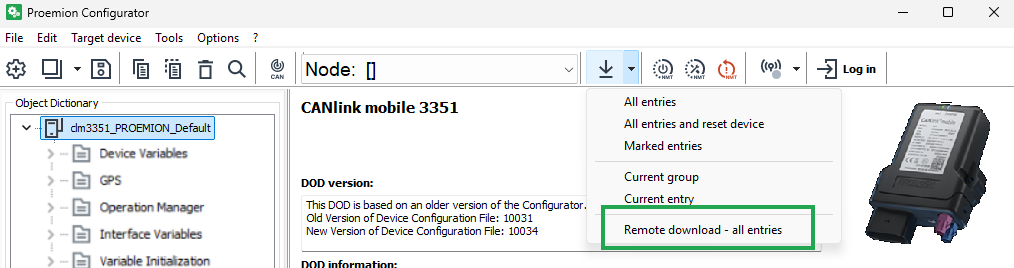
Figure 1: Configuration Update ✓ The REMOTE CONFIGURATION DOWNLOAD TO TARGET(S) window opens.
-
Click on the SELECT DEVICES button in the window REMOTE CONFIGURATION DOWNLOAD TO TARGET(S) window.
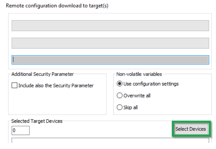
Figure 2: Configuration Update - Targets ✓ The SELECT DEVICES window opens.
-
Enter your DataPlatform user credentials in the SELECT DEVICES window.
-
Click on the LOGIN button.
-
Select the device.
-
Click on the OK button.
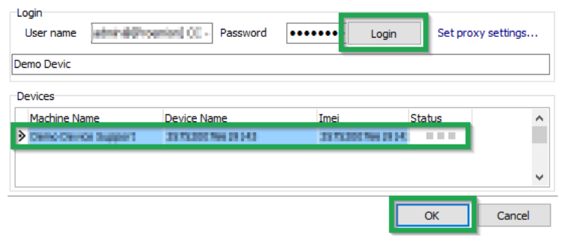
Figure 3: Configuration Update - Select Devices Loss of connection due to incorrect parameters.
The online connection may be lost due to incorrect provider parameters. In most cases, it is not necessary to update the security variables, so this should be avoided.
- Before every update of the security variables, check the provider parameters.
- Refer to Safe Remote Updates Guideline and follow the recommended update process.
-
Click on the START button in the REMOTE CONFIGURATION DOWNLOAD TO TARGET(S) window.
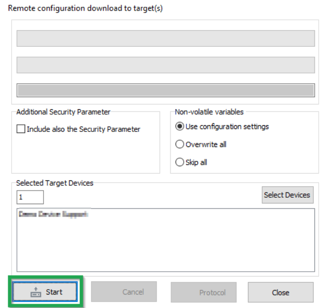
Figure 4: Configuration Update - Download to Target The following warning appears. The user is warned against downloading untested configuration files.
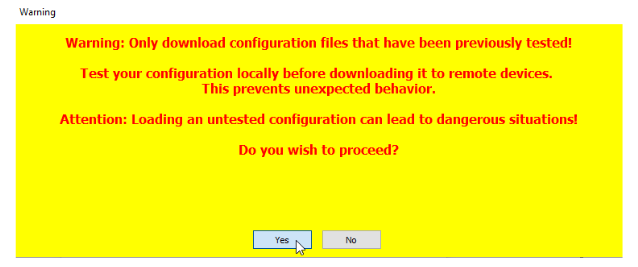
Figure 5: Configuration Update - Download Warning -
Click on the YES button.
The configuration update download starts automatically as soon as the device is online. The download can take several minutes. The device recognizes the configuration file and saves it to its internal memory. The device LEDs light up in a certain sequence.Note
For more information on the LED status indications, see Indicator Elements.
-
Check the DOD version and the DOD activation time in the Communication unit details display of the DataPortal.
The new Config Version with Timestamp will be displayed in the Communication unit details after the next connection of the device. An update log will appear in the file download section of the DataPlatform.
Example of an UpdteLog.txt after a successful configuration update
<LogFileVersion>: 1.0
<BEGIN>: 1607604003
<actSW>: Fw 7.3.0
<actBL>: Bl 9.2
<actDOD>: Proemion
File Size: 20763
Received configuration file
CONFIGURATION DOWNLOAD COMPLETE AFTER 1 ATTEMPT(s).
<newSW>: Fw 7.3.0
<newBL>: Bl 9.2
<newDOD>: CLM Demo Device V2.2.8
<END>: 1607604082
Example of an UpdteLog.txt after a failed configuration update (e.g. due to an incompatible type)
<LogFileVersion>: 1.0
<BEGIN>: 1607604996
<actSW>: Fw 7.3.0
<actBL>: Bl 9.2
<actDOD>: CLM Demo Device V2.2.8
File Size: 2497
Received configuration file
ERROR: Job 0 (0x1018:0x2) -0x3337 is not equal to 0x5301
ERROR: Job 0 (0x1018:0x2) -0x3337 is not equal to 0x5301
ERROR: Job 0 (0x1018:0x2) -0x3337 is not equal to 0x5301
ERROR: ABORT CONFIGURATION DOWNLOAD AFTER 3 ATTEMPTS!
<newSW>: Fw 7.3.0
<newBL>: Bl 9.2
<newDOD>: CLM Demo Device V2.2.8
<END>: 1607605139
CAN
You can perform a configuration update using the CAN interface. To be able to load the configuration file to the device, the device must be connected via a CAN-USB port to a PC on which the configuration file is saved.
-
Connect the device to a PC.
-
Load the configuration to the device.
✓ You have completed the configuration update.
Firmware update
You can load a firmware update to the device by remote maintenance via the DataPlatform or the CAN interface.
Perform a node scan in the Proemion Configurator to identify the currently installed firmware version.
The firmware can be downloaded from our Download Center under: 03_Proemion Tools Software > 01_Software.
In case of problems, the Connectivity Check utility can be used to check the connectivity of our software tools with our services from your local network.
DataPlatform
It is recommended to use the Firmware Management in the DataPortal for the firmware update via the DataPlatform.
The DataPortal firmware management feature provides access to the latest released firmware as well as previous versions.
When updating devices, ensure that all required intermediate versions are installed in the correct order to avoid errors. Some firmware versions are required meaning they must be installed before newer versions can be applied.
In the DataPortal, navigate to Settings → Firmware and Configuration Updates and click on Detailsat the end of the row to check if a firmware version is required.
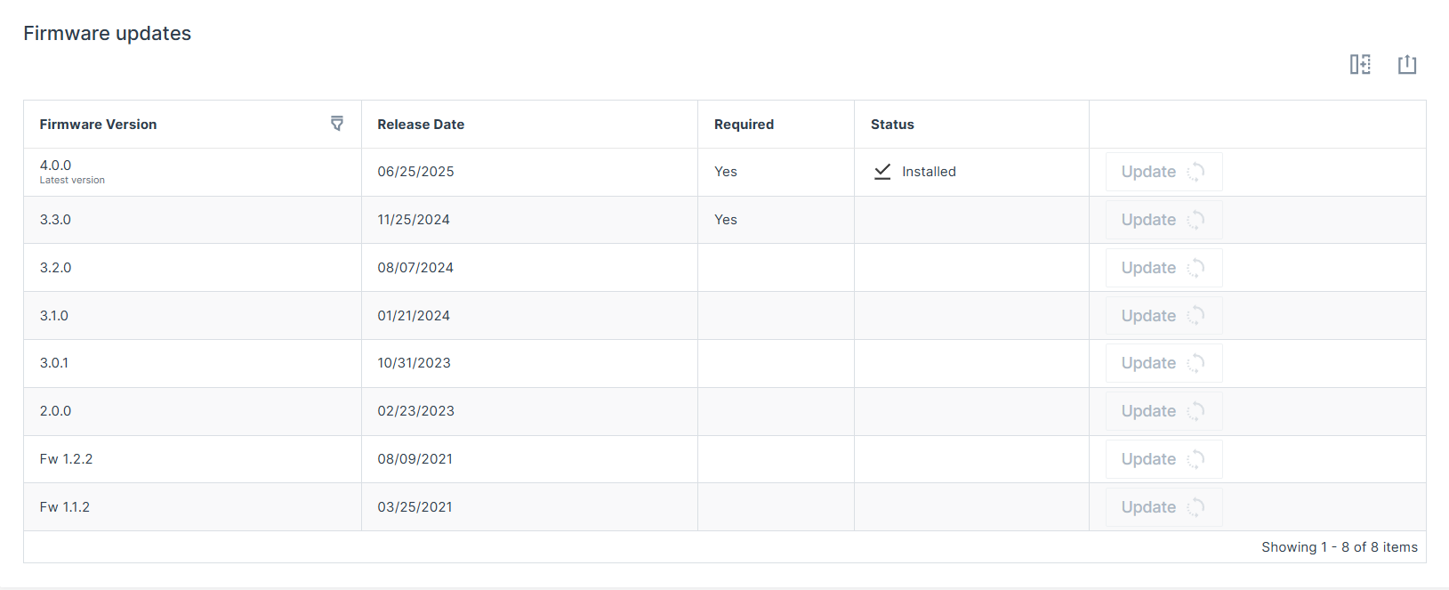
For example, a device running firmware version 3.2.0 cannot be updated directly to version 4.0.0. Version 3.3.0 is required and must be installed first.
Note
As of firmware release version 4.0.0, downgrading to a version lower than 4.0.0 via the DataPlatform (FOTA) is generally no longer possible. This limitation is implemented to meet the cybersecurity requirements under the Radio Equipment Directive (RED).
CAN
In order to load the firmware update (*.bin) on the device via the CAN interface, the device must be connected to a PC via a CAN-USB connection. The Proemion Firmware Programmer software must be installed on the PC and the firmware update stored.
-
Connect the device to a PC.
-
Start the Proemion Firmware Programmer software.
-
Click on FILE > OPEN in the menu and navigate to the memory path for the firmware update (*.BIN).
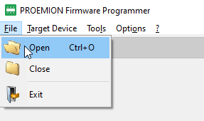
Figure 2: Firmware Update - Open Firmware File -
In the Open FwBin window, select the firmware update (
*.bin) and click on the OPEN button. -
In the main window, click on OPTIONS > COMMUNICATION SETTINGS in the menu.
✓ The COMMUNICATION SETTINGS window opens:
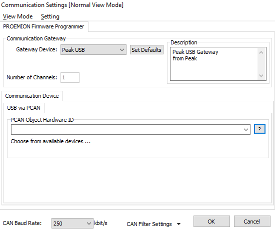
Figure 3: Firmware Update - Communication Settings -
In the COMMUNICATION GATEWAY section, select the device PEAK USB in the GATEWAY DEVICE field.
-
In the Communication Device section, select the PCAN Object Hardware ID.
-
At the bottom of the Communication Settings window, check for the correct CAN baud rate. The default CAN baud rate is 250 kbit/s.
-
Click OK to save the settings. You return to the main window:
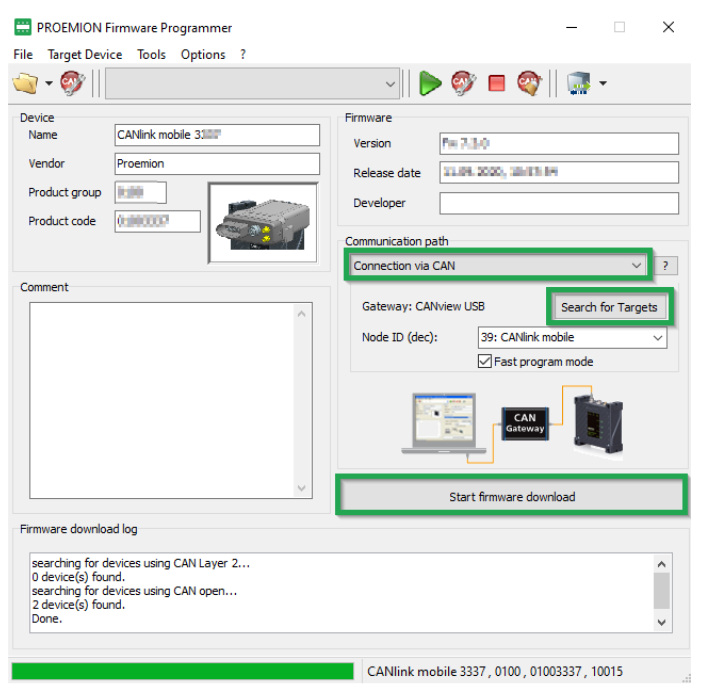
Figure 4: Firmware Update - Progress -
In the list in the COMMUNICATION PATH field, select the interface CONNECTION VIA CAN.
-
Click on the SEARCH FOR TARGETS button.
✓ The device's node ID is adopted.
-
The device's node ID is adopted.
-
Start firmware download.
-
Wait until the update is finished.
✓ During the firmware update, the LEDs light up green in the same sequence.
✓ In the field FIRMWARE DOWNLOAD LOG, the message FIRMWARE DOWNLOADED SUCCESSFULLY appears when the firmware update is complete.
✓ The device restarts automatically.
✓ After the restart, the device uses the updated firmware version.
You can find a tutorial on how to install the firmware to the device in the download section of our website. See Service and Support.
Device Reset
Performing a device reset returns the device to the original settings.
Severely restricted functions due to device reset
Incomplete configuration on the device. Repairs necessary by Proemion.
- Only trained personnel may carry out a device reset.
Complete data loss due to device reset
All logged data is deleted from the device memory.
- Back up your data before a device reset.
Note
During the Device Reset process, the ON LED flashes orange, and the Status LED lights up orange.
Device Reset via CAN
The following table provides an overview of the various reset options available which can be triggered via the CAN interface:
| Function | Index | Subindex | Description |
|---|---|---|---|
| Revert to Factory Configuration1 | 0x1011 |
0x01 |
The factory configuration is restored. All logged data is deleted. |
| Delete All Log Files | 0x1011 |
0x62 |
All logged data stored on the device is deleted. |
| Revert to Firmware Defaults Remote | 0x1011 |
0x63 |
The Standard configuration1 of the current firmware is restored. All logged data is deleted. CAN, Wi-Fi®, BLE and Cellular parameters as well as the factory configuration are retained. |
| Revert to Firmware Defaults plus Format Remote | 0x1011 |
0x64 |
The standard configuration of the current firmware is restored. All logged data and the factory configuration are deleted. CAN, Wi-Fi®, BLE and Cellular parameters are retained. |
| Revert to Firmware Defaults Local | 0x1011 |
0x65 |
The standard configuration of the current firmware is restored. All logged data and parameters are deleted. The factory configuration is retained. |
In order to complete a device reset via the CAN interface, a CANopen software (e.g. CANopen Magic) and a communication gateway (e.g. PCAN-USB - CAN/USB Interface) are required.
The CANopen software writes the value 0x64616F6C to the CANopen object index 0x1011 to trigger a specific reset variant.
In the following example, the device reset using the sub-index 0x65 (Revert to Firmware Defaults Local) is shown:
-
Connect the device to a PC.
-
Start the selected CANopen software.
-
Perform the required steps in the CANopen software to write the value
0x64616F6Cto the object index,0x1011subindex0x65. -
Write the value to the device's object directory.
-
Wait until the device sends the CANopen bootup message to the IDs
0x727and0x728.
✓ The device reverts to the firmware defaults (object 0x1011;_0x65).
✓ The ON LED lights up green.
✓ The STATUS LED lights up blue.
✓ The device has adopted the firmware defaults (CAN Baud Rate 250 kbit/s, CANopen Node ID 39 etc.).
Note
When a Device Reset is being performed, the ON LED flashes in a magenta color and the Status LED orange. For more information on the LED status indications, see Indicator Elements.
You can find a tutorial on how to perform a device reset in the download section of our website. See also Chapter Service and Support.
-
Difference between Factory configuration and Standard configuration:
Factory configuration: With the end-of-line tests (EOL test), Proemion loads a standard configuration (
DOD.bin_file) into the file system of the device. This configuration is called Factory configuration. The content of this file is activated in the device by using the object0x1011, subindex0x01. The factory configuration can be easily overwritten by the customer via the object0x3333, subindex0xF0. This makes it easy for customers to define and install their own configuration as the "factory configuration". If there is no file in the file system, the device configuration will not be changed, but the logged data will always be deleted.Standard configuration: Each firmware version has its own default values in the code for non-volatile configuration parameters. These default values are loaded automatically for fresh devices, for example. The default values of the firmware are loaded via the object
0x1011, subindex0x63. In contrast to the factory configuration, the standard values cannot be changed by customers. These are fixed values in the code memory. ↩↩
Remedies
The following sections contain information on solving problems and on maintenance.
| Problem | Possible cause |
|---|---|
| Device does not function. | Check the power supply via the main plug connector (terminal_30, terminal_31, terminal_15). |
| Device does not receive CAN messages. | Check the CAN connection and the configuration of the CAN messages. Check whether the bus terminating resistor is correctly mounted. |
| Device does not receive GNSS signals. | Check the antenna connection and cable for damage. Position the antenna or the device so that it directly points to the sky. |
| Device does not receive a cellular signal. | Check the antenna connection and cable for damage. Check the eSIM configuration in the eSIM - Specials object dictionary. Position the antenna or the device so that it directly points to the sky. |
| Device does not log data. | Check the CAN baud rate in the configuration. Check in the configuration whether the device is in "Operational" mode. Check the logging configuration. |
| Device with integrated battery does not initialize after switching on or firmware update. | Use a suitable tool to press the reset button on the main plug connector to restart the device. |
Support Request
The software tool for further troubleshooting is the DeviceAnalyzer software, available in the Download Center:
- for the
CANlink® mobile 3000 DeviceAnalyzer Setup.exe, navigate to:03_Proemion Tools Software > 01_Software > 08_CANlink mobile 3000 DeviceAnalyzer - for the software manual, navigate to:
03_Proemion Tools Software > 01_Software > 00_Documentation
If you do not find the solution to your problem in this manual, contact our Proemion support. See chapter Service and Support.
The support team requires the following information to help you:
-
Connect the USB Diagnostics Cable to your PC and create a device log with the DeviceAnalyzer software when the problem appears. While the device log is recorded, click on Restart. This will allow the support team to also evaluate the initialization phase of the device.
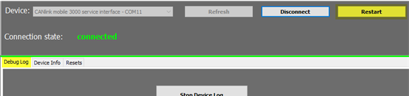
-
Read out all device and security variables with the DeviceAnalyzer.
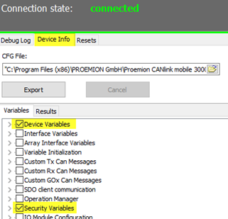
-
What is the condition of the status LED after the restart was triggered by the DeviceAnalyzer software? If possible, create a video of the status LEDs in addition to the device log including the restart.
-
Send the device log, the video of the status LEDs and the required output about the device and security variables by creating a ticket at Support.
Connection Problems to the DataPlatform
If the device cannot establish a connection to the DataPlatform, check the following:
-
Has the configuration been correctly loaded on the device? See chapter Configuration update.
-
Are the device LEDs lighting up correctly? See Chapter Indicator elements (LED).
-
Are the contract and device settings in the DataPortal correct?
-
Are the configured mobile communication parameters within the device configuration correct?
You can find more information in the following chapter.
DataPortal
Check that the contract and device settings in the DataPortal are correct.
-
Login at the DataPortal.
-
Click on Administration.
-
Click on Overview.
-
Click on COMMUNICATION UNITS.
-
Enable the checkbox Include sub-organizations.
-
Enter the device name or machine name in the corresponding search box.
-
Check in the machine column if the correct/expected machine name is displayed.
-
Check the Organization column if the device is allocated to the correct organization unit.
-
Click on the DETAILS button of the corresponding communication unit.
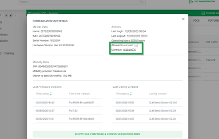
✓ The detail view of the selected device is displayed.
-
Click on the contract number from the contract field to check in the contract overview if the device has a valid contract.
✓ The contracts view of the selected device is displayed.
-
Click on Details.
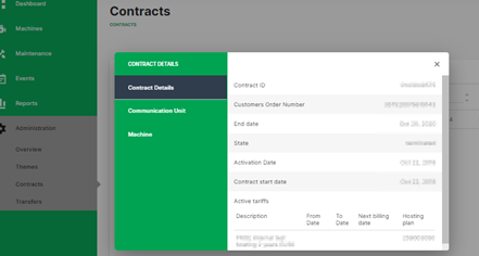
✓ The contract details of the selected contract are opened.
-
Check the contract details for the correct settings.
The settings for the communication unit and machine can also be checked in this window.
Device Configuration
Check if the mobile communication parameters in the Proemion Configurator are correct. The variables belong to the Security Variables group. You may use the tables below as a copy/paste template for the information to the support team.
-
Establish a physical CAN connection with a supported gateway device.
-
Start the Proemion Configurator software.
-
Select the correct gateway device and com port in the communication settings.
-
Open the corresponding device configuration file.
-
Open the tab Specials.
-
Read out the configured Security Variables according to the table below and make a note for later reference. If there are security variables missing in the used device configuration, they can be added with a right mouse click onto the tree element
Security Variables.Security Variable Default Value with Proemion eSIM card Read value Remote Server Address gateway.proemion.comRemote Server Port 61200Enable encrypted data transfer 1Online Mode Handling 1[E-SIM] SIM PIN empty [E-SIM] Roaming Handling 1[E-SIM] Operator Selection Mode 0[E-SIM] Operator Selection Code 0[E-SIM] DNS1 [empty][E-SIM] DNS2 [empty][E-SIM] ISP Username [empty][E-SIM] ISP Password [empty][E-SIM] APN iot.truphone.com1[E-SIM] SMS Service Center Address +491710760000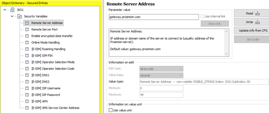
-
Open the Application tab in your configuration.
-
Read out the device variables according to the table below. If there are device variables missing in the used configuration, they can be added by right mouse click onto the object dictionary group Device Variables.
Device Variable Default Value Read value Mobile - Disconnect Mode (embedded_SIM) 1Mobile - Signal Quality (read-only) Mobile - Network State (read-only) Mobile - Modem Result (read-only) Mobile - Network Mode Select 0 Mobile - Network Mode Current (read-only) Mobile - Antenna Status (read-only) Mobile - failure reconnect delay 30 Mobile - State Machine current state code (read-only) Mobile - State Machine Error Code (read-only) Mobile - CMS Error Number (read-only) Mobile - CME Error Number (read-only) Mobile - SIM pin error flag (read-only) Mobile - Engine IMEI Number (read-only) Mobile - SIM Card ID (ICCID) (read-only) Mobile - Active Network Provider (read-only) Mobile - Local IP Address (read-only) Mobile - Engine Version (read-only) Mobile - Maximum Cellular Receive Delay 5000 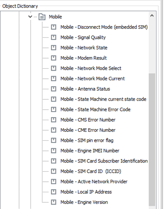
-
Provide the tables with the read-out values to the Proemion support.
Device Configuration for 1Global SIM
Follow steps 1. to 9. as described in Device Configuration, but use the following Security Variables for devices with 1Global SIM cards.
Note
The ICCID of these SIM cards starts with 894447.
| Variable | Value |
|---|---|
| APN | iot.truphone.com |
| SMS Service Center Address | [blank] |
| Roaming Handling | 1 |
| All other settings | [blank] |
Device Configuration for Nano-SIM Türkiye
Follow steps 1. to 9. as described in Device Configuration, but use the following Security Variables for devices with Nano-SIM Türkiye SIM cards.
Note
The ICCID of these SIM cards starts with 899001.
| Variable | Value |
|---|---|
| APN | internet |
| SMS Service Center Address | [blank] |
| Roaming Handling | 1 |
| All other settings | [blank] |
-
The APN is preconfigured for Proemion eSIM cards and should not be modified unless explicitly instructed by Proemion support. ↩
Maintenance
Maintenance
Check all connectors for a firm connection regularly.
Check the state of the integrated battery. If the battery is totally discharged or has reached the maximum number of 500 charge cycles, contact the Proemion Support.
Risk of property damage
Do not open the device housing unless you are explicitly instructed to do so. Use only approved tools and follow the specified procedures. Unauthorized opening may damage the device and may affect warranty coverage. The device must be inspected and repaired only by trained Proemion service technicians. Contact our Service and Support.
For more information on the integrated battery, see chapter battery.
Cleaning
Risk of property damage
Damage to the device due to water penetration
-
The device was tested against water jets according to IPxK5 of ISO 20653 standard. Different loads, e.g., with a pressure washer or a higher flow rate, do not correspond to the intended use.
-
Never clean the CANlink mobile device with a pressure washer or similar.
To avoid damage caused by liquid ingress, no high-pressure cleaners may be used for cleaning. In order to remove contamination, you should also avoid using jet water if possible. Instead, use a damp cleaning cloth with a solvent-free and acid-free cleaning liquid. Make sure the device is mounted as recommended to avoid liquid ingress, see Mounting Orientation.
Packaging and Transport
This chapter contains information on packing and transportation.
Risk of property damage
-
Only store and transport the device in a temperature range of -40 °C … +85 °C / -40 °F … +185 °F.
-
For devices with an integrated battery, only store and transport the device in a temperature range of -20 °C … +60 °C / -4 °F … +140 °F.
-
Protection class IP6K7 is only ensured when all connectors are properly sealed using protection caps.
-
Close all connectors with protection caps.
Lithium-polymer battery transport
According to applicable transport regulations for lithium batteries, devices containing such batteries, or their packaging, must be specially labeled.
Prior to shipping, please contact our Service and Support.
- Only ship the device in appropriately labeled packaging.
Disposal
This chapter contains information on correct disposal.
Regulations in the European Union
Note
Observe local regulations for disposal of the device, the accessories and the packaging material.
 |
According to the Directive on Waste Electrical and Electronic Equipment (WEEE), the device must not be disposed of in household waste. The device contains a lithium-polymer battery which can contain toxic and polluting heavy metals. Take the device to a collection point for waste electrical and electronic equipment for correct disposal. |
Environmental damage due to lithium-polymer battery
According to the valid transport regulations for lithium batteries, devices containing such batteries, or their transport packaging must be specially labeled.
Prior to shipping, please contact our Service and Support.
- Only ship the device in a packaging that is appropriately labeled on the outside.
Regulatory and Compliance
Conformity
The device meets the requirements of the following standards and legal requirements.
The device is designed to be used in systems that must comply with applicable legal and regulatory requirements prior to commissioning.
The system integrator is responsible for ensuring that all applicable local laws, regulations, and provisions are observed.
| Symbol | Declaration of Conformity | Status |
|---|---|---|
 |
Simplified CE Declaration of Conformity | Pending |
 |
E1 Compliant | Pending |
 |
ISED Compliant | Pending |
 |
FCC Compliant | Pending |
 |
TELEC compliant for Japan | Pending |
 |
KC compliant for Korea | Pending |
CE Notes European Union
The devices described in this manual may only be used in mobile or stationary systems in which the distance between antennas and persons is at least 20 cm.
Antennas may only be operated in conjunction with other antennas or transmitters if the required separation distance is maintained.
Changes or modifications to this device not expressly approved by the manufacturer can void the user's authority to operate the device under CE rules.
Antenna Requirements (Cellular)
The maximum antenna gain (including cable and connector loss) must not exceed the following limits for the supported frequency bands.
4G/LTE Band (dBi):
- B1: 11.85
- B3: 11.35
- B7: 11.96
- B8: 8.46
- B20: 8.23
- B28: 7.49
- B34: 11.96
- B38: 11.96
- B40: 11.96
- B41: 11.96
Antenna Requirements (Wi-Fi / BLE)
The maximum antenna gain (including cable and connector loss) must not exceed the following limits for the supported wireless interfaces.
Wireless Interfaces (dBi):
- BLE: 3.3
- WiFi 2.4 GHz: 3.3
- WiFi 5 GHz: 4.4
Bluetooth (ETSI)
The allowed maximum equivalent isotropically radiated power (EIRP) is:
- Bluetooth LE: max 4.72 dBm at 2402 - 2480 MHz
Wi-Fi (ETSI)
The allowed maximum equivalent isotropically radiated power (EIRP) is:
- 2.412 – 2.472 GHz: max 19.86 dBm
- 5.15 – 5.35 GHz: max 19.88 dBm
- 5.47 – 5.725 GHz: max 19.88 dBm
- 5.725 – 5.785 GHz: max 13.96 dBm
Devices with a Wi-Fi interface are restricted to indoor use only when operating in the frequency range 5150 to 5350 MHz in the following countries:

FCC Notes USA
The devices described in this manual may only be used in mobile or stationary systems in which the distance between antennas and persons is at least 20 cm. The antennas must further not be co-located or operated in conjunction with any other antennas or transmitters. Changes or modifications to the device not expressly approved by the manufacturer can void the user's authority to operate the device under FCC rules.
FCC Part 15 Statement
This device complies with Part 15 of the FCC Rules. Operation is subject to the following two conditions:
- This device may not cause harmful interference
- This device must accept any interference received, including interference that may cause undesired operation
Interference Information
This device has been tested and found to comply with the limits for a Class B digital device pursuant to Part 15 of the FCC rules.
These limits are designed to provide adequate protection against harmful interference in a residential installation.
This device generates, uses, and can radiate radio frequency energy and, if not installed and used in accordance with the instructions, may cause interference to radio communications. There is no guarantee that interference will not occur in a particular installation.
If this device does cause interference to radio or television reception, which can be determined by switching the device on and off, the user is advised to try to correct the interference by one or more of the following measures:
- Realign the receiving antenna or put it in a different place.
- Increase the distance between the device and the receiver.
- Connect the device and the receiver to different supply circuits.
- Consult the dealer or an experienced radio/TV technician for help.
Antenna Requirements (Cellular)
The maximum antenna gain (including cable and connector loss) must not exceed the following limits for the supported frequency bands.
4G/LTE Band (dBi):
- FDD 2: 8.0
- FDD 4: 5.0
- FDD 5: 9.41
- FDD 7: 8.0
- FDD 8: 9.78
- FDD 12: 8.7
- FDD 13: 9.16
- FDD 25: 8.0
- FDD 26: 9.36
- FDD 66: 5.0
- FDD 38: 8.0
- FDD 41: 8.0
ISED Notes Canada
English
This product meets the applicable Innovation, Science and Economic Development Canada technical specifications.
This Class B equipment complies with the applicable ISED RSS standards and CAN ICES-003. Operation is subject to the following two conditions:
- This device may not cause interference
- This device must accept any interference, including interference that may cause undesired operation of the device
Changes or modifications to this device not expressly approved by the manufacturer can void the user's authority to operate the device under ISED rules.
Radiation Exposure
This device complies with radiation exposure limits prescribed for an uncontrolled environment for fixed and mobile use conditions.
This equipment should be installed and operated with a minimum distance of 20 cm between the radiator and the body of the user or nearby persons.
Antenna Requirements (Cellular)
The maximum antenna gain (including cable and connector loss) must not exceed the following limits for the supported frequency bands.
4G/LTE Band (dBi):
- FDD 2: 8.0
- FDD 4: 5.0
- FDD 5: 6.12
- FDD 7: 8.0
- FDD 12: 5.63
- FDD 13: 5.95
- FDD 25: 8.0
- FDD 26: 6.12
- FDD 66: 5.0
- FDD 38: 8.0
- FDD 41: 8.0
Antenna Requirements (Wi-Fi / BLE)
The maximum antenna gain (including cable and connector loss) must not exceed the following limits for the supported wireless interfaces.
Wireless Interfaces (dBi):
- BLE: 3.3
- WiFi 2.4 GHz: 3.3
- WiFi 5 GHz: 4.4
Wi-Fi Restrictions
Applies to devices with Wi-Fi interface.
This device is restricted to indoor operation only in the band 5150–5250 MHz to reduce the potential for harmful interference to co-channel mobile satellite systems.
Original equipment manufacturer (OEM) devices installed in vehicles are permitted.
High-power radars are allocated as primary users (priority users) of the bands 5250–5350 MHz and 5650–5850 MHz and may cause interference and/or damage to this device.
This device is not capable of transmitting in the band 5600–5650 MHz in Canada.
Français
Ce produit est conforme aux spécifications techniques applicables d'Innovation, Sciences et Développement économique Canada.
Cet équipement de classe B est conforme aux normes ISDE RSS applicables et à la norme CAN ICES-003. Son fonctionnement est soumis aux conditions suivantes :
- Cet appareil ne doit pas provoquer d’interférences
- Cet appareil doit accepter toute interférence, y compris celles pouvant entraîner un fonctionnement indésirable
Les changements ou modifications de cet appareil non expressément approuvés par le fabricant peuvent annuler le droit de l'utilisateur à utiliser l'appareil selon la réglementation ISDE.
Exposition aux rayonnements
Cet appareil est conforme aux limites d'exposition aux rayonnements prescrites pour un environnement non contrôlé dans des conditions d'utilisation fixe et mobile.
Cet équipement doit être installé et utilisé avec une distance minimale de 20 cm entre le radiateur et le corps de l'utilisateur ou des personnes à proximité.
Gain d’antenne (cellulaire)
Le gain d'antenne maximal (y compris les pertes du câble et du connecteur) ne doit pas dépasser les valeurs suivantes pour les bandes prises en charge par l'appareil.
4G/LTE (dBi):
- FDD 2 : 8.0
- FDD 4 : 5.0
- FDD 5 : 6.12
- FDD 7 : 8.0
- FDD 12 : 5.63
- FDD 13 : 5.95
- FDD 25 : 8.0
- FDD 26 : 6.12
- FDD 66 : 5.0
- FDD 38 : 8.0
- FDD 41 : 8.0
Exigences d’antenne (WiFi / BLE)
Le gain d’antenne maximal (y compris les pertes du câble et du connecteur) ne doit pas dépasser les limites suivantes pour les interfaces sans fil prises en charge.
Interfaces sans fil (dBi):
- BLE : 3.3
- WiFi 2.4 GHz : 3.3
- WiFi 5 GHz : 4.4
Restrictions Wi-Fi
S'applique aux appareils avec interface Wi-Fi.
Cet appareil est limité à un fonctionnement en intérieur uniquement dans la bande 5150–5250 MHz afin de réduire le potentiel d'interférences nuisibles aux systèmes mobiles par satellite sur le même canal.
Les dispositifs OEM installés dans des véhicules sont autorisés.
Les radars haute puissance sont considérés comme utilisateurs principaux (prioritaires) des bandes 5250–5350 MHz et 5650–5850 MHz et peuvent causer des interférences et/ou endommager cet appareil.
Cet appareil n'est pas capable d'émettre dans la bande 5600–5650 MHz au Canada.
Warranty and Liability
Proemion assumes no liability for defects caused by normal wear, external influences and incorrect installation, operation or maintenance. This also applies if the customer or a third party modifies the devices, any accessories, or the software without permission from Proemion.
Annex
This chapter contains technical data and assembly drawings.
Technical Drawings
All housing forms include a Main Plug Connector for power and CAN bus communication.
Housing Form A - No Additional Connectors
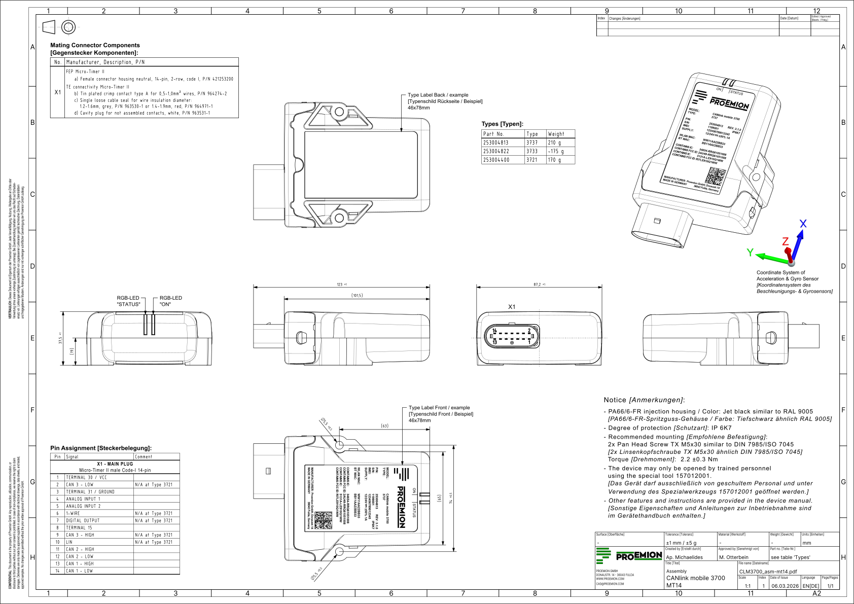
Housing Form B - External Antenna Connector
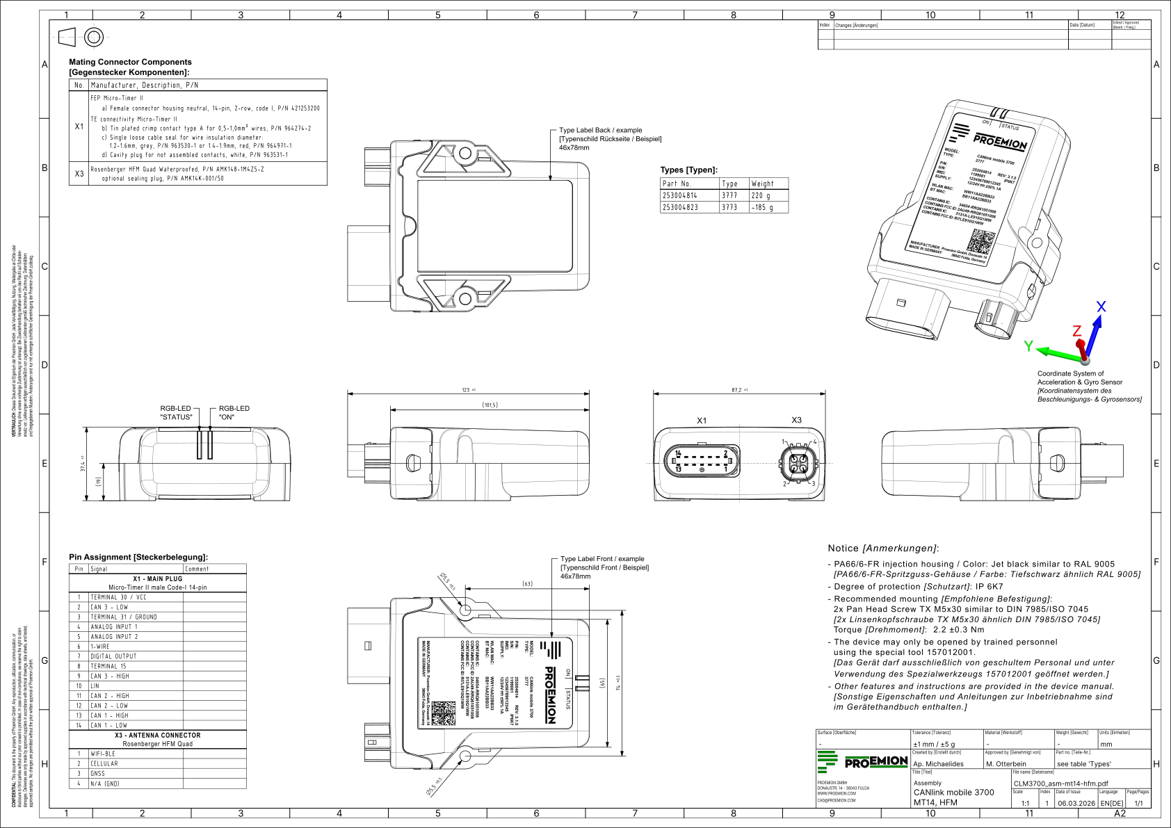
Housing Form C - Ethernet Connector
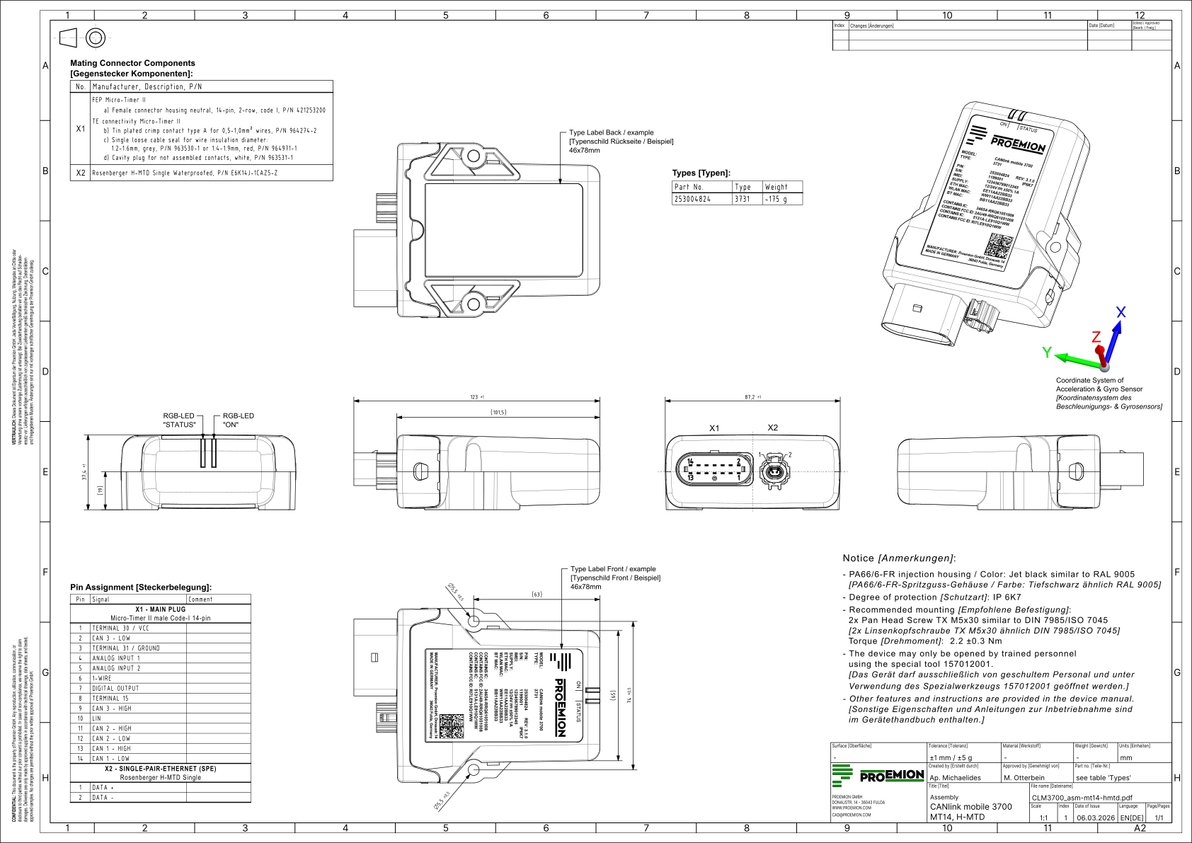
Housing Form D - Ethernet and Antenna Connectors
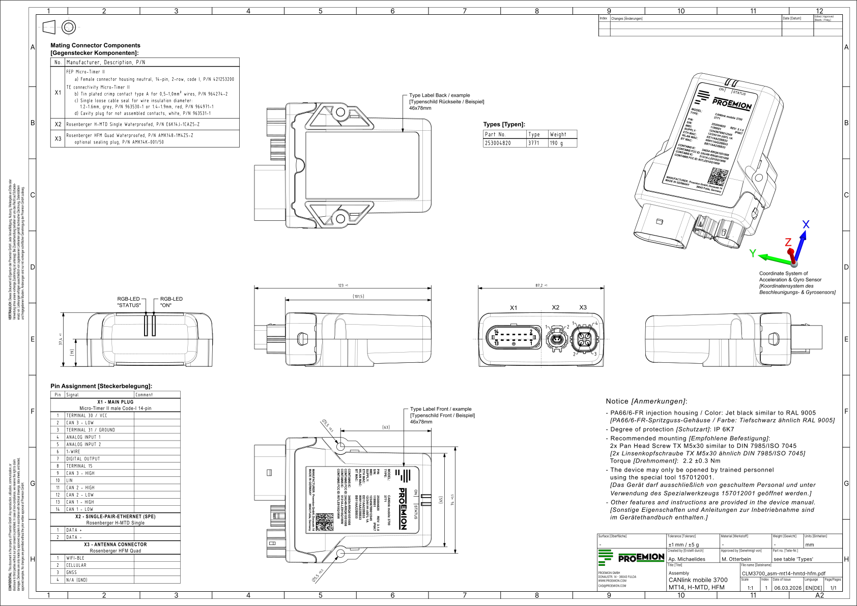
PDF files of the assembly drawings are available in the Download Center under:
01_Proemion_Devices > 01_CANlink mobile 3700 > 01_Documentation > Drawings
Technical Specifications
This chapter contains the technical specifications of the device.
Mechanical
| Parameter | Value |
|---|---|
| Housing | GH1209 |
| Dimensions (L/W/H) | ≤ 123 / ≤ 87.5 / ≤ 37.5 mm |
| Mounting | 2x M5 mounting holes |
| Protection class | IP6K7 |
| Material | PA66 |
| Color | Black |
| Weight | < 220 g |
Electrical
| Parameter | Value |
|---|---|
| Supply voltage Terminal 30 | 6 - 36 VDC |
| Reverse polarity protection | -36 VDC |
| Overvoltage protection | +36 VDC |
| Operating current average @24 VDC | < 200 mA |
| Peak current @24 VDC | 1 A |
| Sleep current @24 VDC | < 500 µA |
| Battery type | Lithium-polymer |
| Battery capacity | 7.4 Wh |
| Battery charging current (internal Vbat) | < 500 mA |
| Status indicators | 2x RGB LEDs |
| Power modes | Normal, battery, sleep |
I/O Characteristics
| Parameter | Value |
|---|---|
| Main connector | Micro Timer II, 14 contacts |
| Analog inputs | 2x (0-15 VDC, 12-bit resolution) |
| Terminal 15 input | Yes |
| Digital output | 1x (6-36 VDC / 500 mA) |
Processor and Memory
| Parameter | Value |
|---|---|
| Microcontroller (MCU) | STM32H7 |
| CPU frequency | ≤ 400 MHz |
| RAM | 9 MB |
| Flash | 130 MB |
| NV-RAM | 64 KB |
Sensors
| Parameter | Specification |
|---|---|
| Temperature (not calibrated) | -40 to +85 °C |
| Acceleration (not calibrated) | 3 axes, ±16 g, 16-bit |
| Gyroscope (angular rate sensor, not calibrated) | 3 axes, ±250 °/s, 16-bit |
Cellular Connectivity
| Parameter | Value |
|---|---|
| Technology | 4G LTE Cat 1bis |
| LTE bands | B1, B2, B3, B4, B5, B7, B8, B12, B13, B18, B19, B20, B25, B26, B28, B34, B38, B39, B40, B41, B66 |
| Max theoretical downlink | 10 Mbit/s |
| Max theoretical uplink | 5 Mbit/s |
| Max transmit power | +23 dBm |
| Receiver sensitivity | -98 dBm |
| SIM | Embedded MFF2 Proemion SIM and nano-SIM slot |
| Antenna | Single, integrated or external Quad HFM connector (Z-code) |
Wi-Fi®
| Feature | Specification |
|---|---|
| Standard | 802.11 ax/a/b/g/n |
| Transmit/receive mode | 1x1 SISO (single transmit/receive antenna) |
| Channel bandwidth | ≤ 20 MHz |
| Frequency bands | 2.4 GHz / 5 GHz |
| Max PHY data rate | up to 96 Mbit/s |
| Max transmit power | 2.4 GHz: +18.5 dBm / 5 GHz: +18 dBm |
| Receiver sensitivity | ≥ -94 dBm @ 2.4 GHz / ≥ -86 dBm @ 5 GHz |
| Security | WPA2-Personal/Enterprise, WPA3-Personal/Enterprise |
| Modes | Station, SoftAP |
| Antenna | Single, integrated or external Quad HFM connector, Z-code (combined with Bluetooth) |
Bluetooth Low Energy (BLE)
| Feature | Specification |
|---|---|
| Version | 5.1 |
| Classic Bluetooth | Not supported |
| Frequency band | 2.4 GHz |
| Max PHY data rate | 1 Mbit/s (LE 1M PHY) |
| Max transmit power | +0.8 dBm |
| Receiver sensitivity | -89 dBm |
| Mode | Gateway mode, CA-CAN-BLE bridge mode |
| Antenna | Integrated or external Quad HFM connector, Z-code (combined with Wi-Fi®) |
GNSS/Positioning
| Feature | Specification |
|---|---|
| Satellite systems | GPS / Galileo / BeiDou / GLONASS / QZSS concurrent reception |
| Position accuracy | ≤ 2.5 m (CEP 50%, 24 h static, -130 dBm, >6 satellites in view) |
| Update rate | 1 Hz |
| Cold start | < 60 s |
| Warm start | < 10 s |
| Hot start | < 5 s |
| Receiver sensitivity GPS | cold start -148 dBm, tracking -165 dBm |
| Antenna | Integrated or external Quad HFM connector (Z-code) for active antenna |
CAN Interfaces
| Feature | Specification |
|---|---|
| CAN1, CAN2, CAN3 interfaces | CAN (2.0 A/B): ISO 11898-2 |
| Max PHY data rate | 1 Mbit/s |
| CAN protocols | CANopen, Layer 2, J1939 |
| Custom protocols | On request |
| Wake-up capability | CAN1 and CAN3 |
Other Interfaces
| Feature | Specification |
|---|---|
| LIN | v2.2A, physical layer ISO 17987-4, commander mode, 20 kbit/s |
| 1-Wire | Asynchronous serial, half-duplex, commander mode, 3.3 V level, no supply for responder |
| Single Pair Ethernet (SPE) | IEEE 802.3bw 100BASE-T1, max. PHY data rate 100 Mbit/s |
| SPE connector | H-MTD connector (Z-code) |
| Wake-up capability (SPE) | TC10 |
Note
Single Pair Ethernet (SPE) hardware is available but currently not supported by the firmware.
Security
| Feature | Supported |
|---|---|
| Trusted Platform Module | Yes |
| Secure firmware update | Yes |
| Encrypted data transmission according to TLS | Yes |
| Bidirectional authentication |
Environmental
| Parameter | Specification |
|---|---|
| Operating temperature (Types without battery) | -40 to +80 °C |
| Operating temperature (battery discharge) | -20 to +50 °C |
| Operating temperature (battery charge) | 0 to +35 °C |
| Humidity | < 90% |
| Vibration | 10 g |
| Shock | 30 g |
| Material handling equipment | EN 12895 |
| Earth-moving machinery | ISO 13766-1 |
| Road vehicle equipment | ISO 16750-2 |
| Electromagnetic compatibility (EMC) | EN 61000-6-2 |
| Service life | ≥ 10 years |
Status Indicators
See Indicator Elements for the meaning of the device's status LEDs.
Service and Support
The latest versions of the drivers, software, firmware, and documentation are available at Document Library.
Do you need help or want to report a bug?
Visit Proemion for more information, or raise a ticket via Support.
Firmware Updates and Support
To ensure the best performance and security of your devices, we strongly recommend always installing the latest firmware provided by Proemion.
Please note:
We do not provide technical support for issues caused by outdated firmware.
Errors resulting from outdated firmware are considered non-qualified errors and are not covered by warranty or support.
Regular firmware updates are essential to maintaining the functionality of your devices.
If you need assistance with the update process, please contact our Service and Support.
For more information on the Firmware Update, check the device manual of your device at the Document Library.