External Roof Antenna
The External roof antenna, LTE/GNSS/Wi-Fi, 3 m cable, HFM-Quad connector (Z-code) (part number 157000136) is compatible with CANlink® mobile 3700 devices with an external antenna connector (Housing Form B/D). See Available Models and Types for available model types.
Technical Specifications
The following tables list the antenna's electrical, mechanical, and environmental specifications.
Cellular
| Parameter | Value |
|---|---|
| Standards | 5G, 4G, 3G and 2G |
| Frequency range (Peak Gain) | 617-960 MHz (~3.1 dBi) 1427-2690 MHz (~2.7 dBi) 3300-5000 MHz (~0.9 dBi) 5150-5925 MHz (~-0.4 dBi) |
The antenna's broadband cellular design covers 2G to 5G frequency ranges; CANlink® mobile 3700 itself uses 4G LTE Cat 1bis.
Wi-Fi/ISM
| Parameter | Value |
|---|---|
| Standards | Wi-Fi, BT, ZigBee, ISM |
| Frequency range (Peak Gain) | 2410-2490 MHz (~-0.2 dBi) 4920-5925 MHz (~1.7 dBi) 5925-7125 MHz (~1.6 dBi) |
GNSS
| Parameter | Value |
|---|---|
| Standards | GPS/QZSS/Galileo, GLONASS |
| Frequency range (Passive Gain) | GPS/QZSS/Galileo: 1575.42 MHz (~3.6 dBi) GLONASS: 1598-1606 MHz (~3.6 dBi) |
Mechanical
| Parameter | Value |
|---|---|
| Mounting | Screw mount, M18 x 1, max. 5 Nm tightening torque |
| Ground plane | Independent - no metallic mounting surface required |
| Dimensions (W x L x H) | 80 x 74 x 25.6 mm |
| Housing material | PC/ASA |
| Radome color | Black |
Environmental
| Parameter | Value |
|---|---|
| Operating/storage temperature | -40 °C to +85 °C |
| Protection level | IP67, IP69 |
| Substance compliance | RoHS |
Mount the Antenna
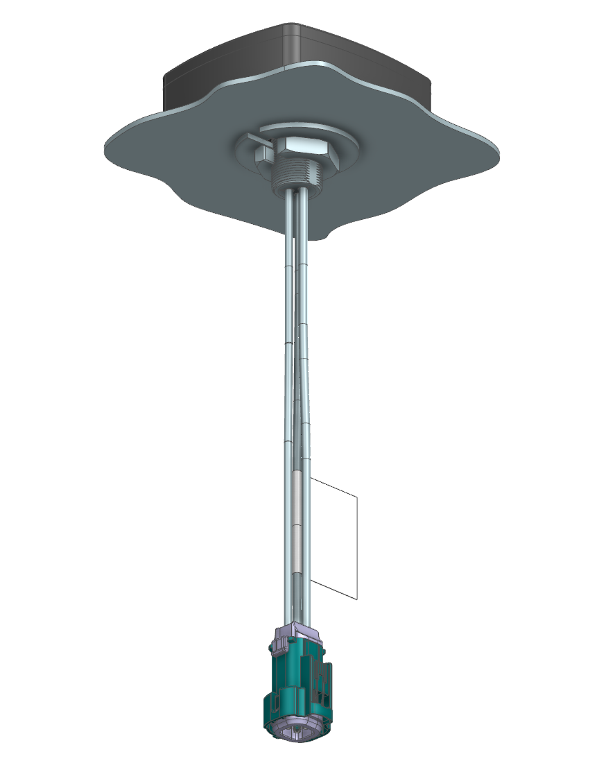
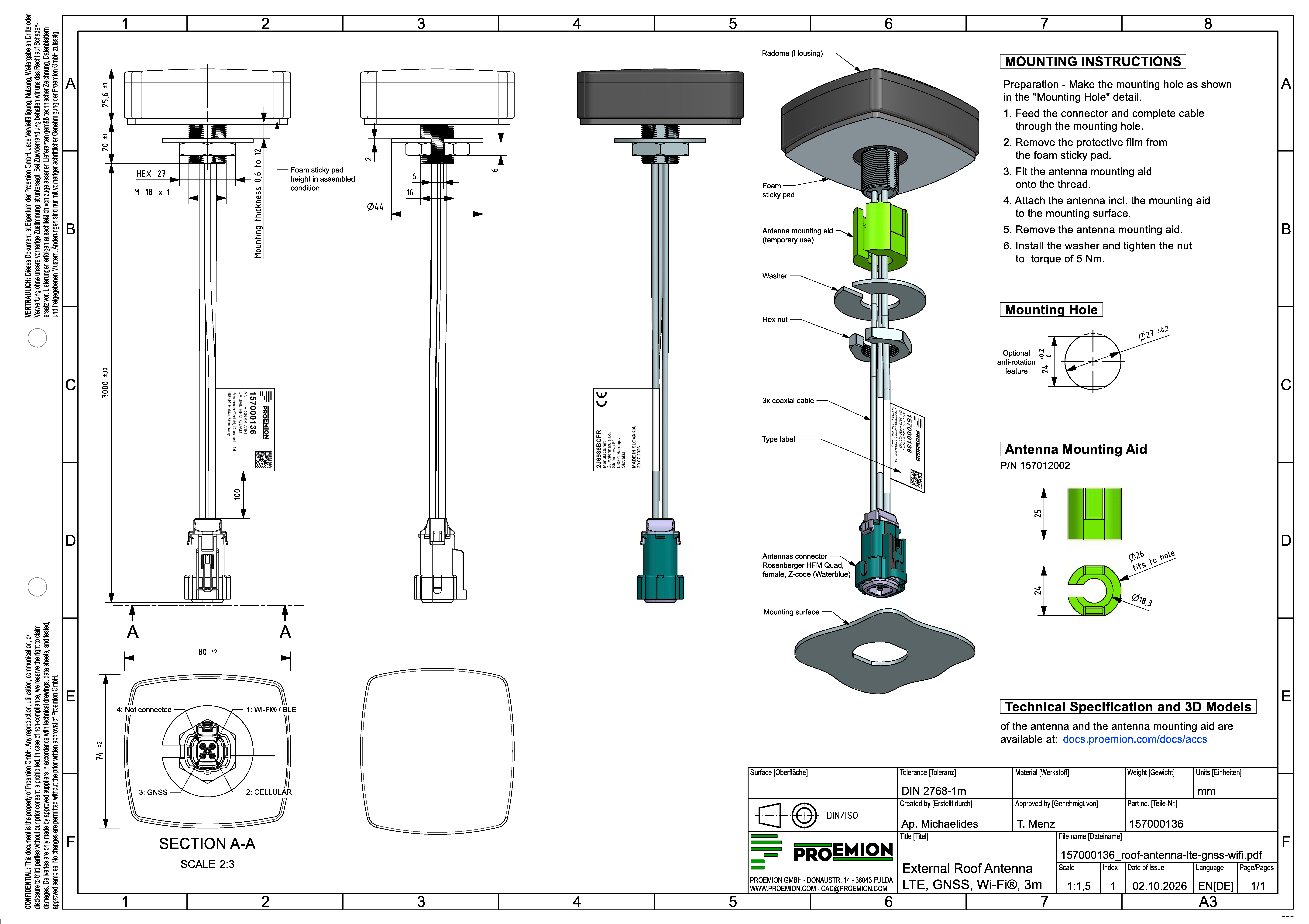
The antenna is designed for permanent mounting through a panel, e.g. a vehicle roof, using its M18 x 1 threaded stud, washer, and nut. Since the antenna's connector is wider than the stud itself, the Antenna Mounting Aid (part number 157012002) is required during installation to center the antenna in an oversized mounting hole, for mounting surfaces between 0.6 and 12 mm thick.
Preparation: Make the mounting hole according to the following detail, optionally including a 24 mm flat as an anti-rotation feature that matches a corresponding flat on the Antenna Mounting Aid.
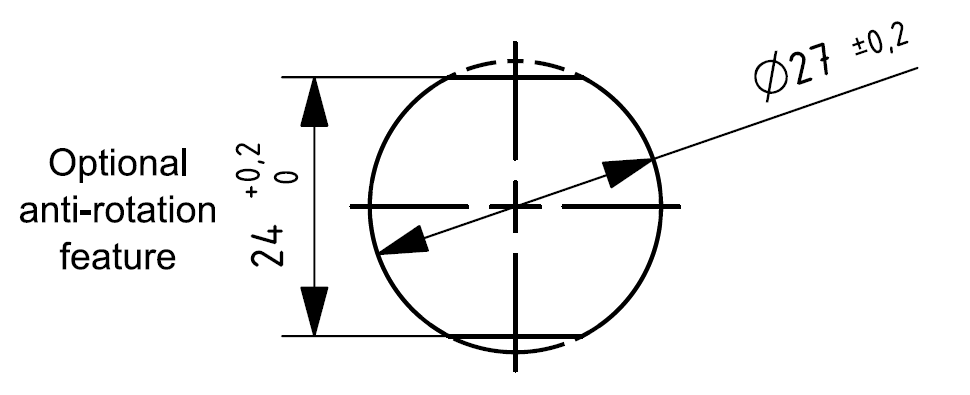
To mount the antenna, proceed as follows:
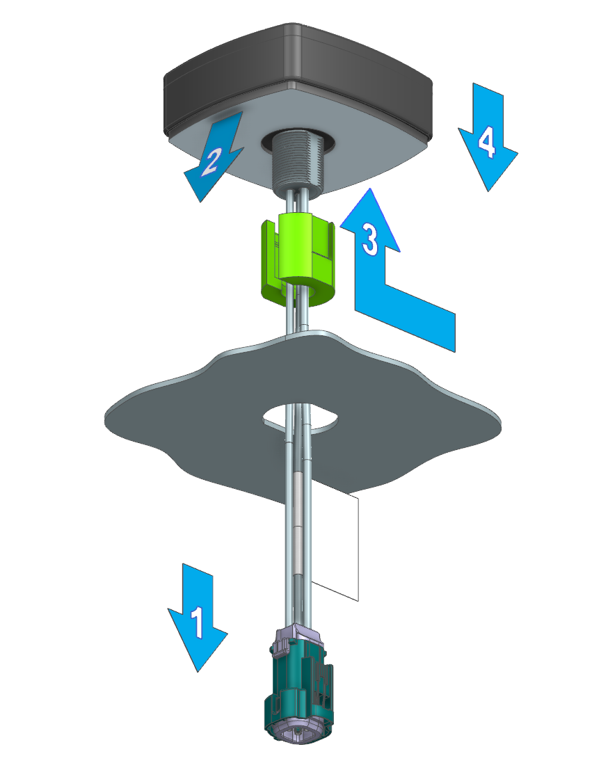
- From the outside, feed the antenna's connector and cable through the mounting hole.
- Remove the protective film from the antenna's foam sticky pad.
- Feed the cable through the Antenna Mounting Aid's slot, then fit the Antenna Mounting Aid onto the antenna's threaded stud to center the antenna in the hole.
-
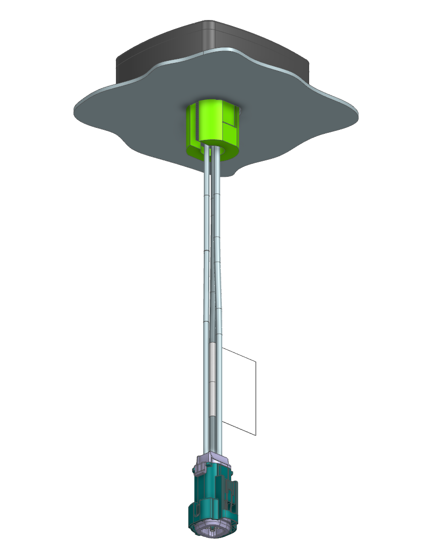
Press the antenna, together with the Antenna Mounting Aid, onto the mounting surface.
-
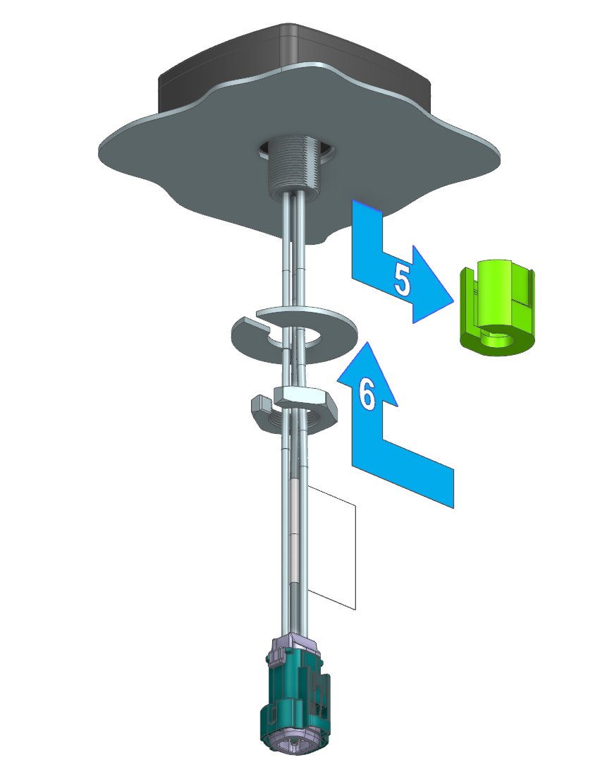
Remove the Antenna Mounting Aid.
-
From the inside, install the washer and nut, and tighten to the maximum torque of 5 Nm using a size 27 wrench.
Warning
Do not exceed the maximum tightening torque of 5 Nm - this can damage the antenna housing.
References
The following drawing provides the full mechanical reference, including dimensions, pin assignment, and the Antenna Mounting Aid detail.
You will find the following reference material in the Download Center under: 01_Proemion_Devices > 90_Accessories
-
3D data of the antenna
-
3D data of the Antenna Mounting Aid, for 3D printing