Items Description
This page describes all configurable elements of a PDC file in the order they appear in the configuration. It covers metadata, shared definitions, signal definitions, error message parsing, parsing rules, actions, and permissions.
Metadata
Name
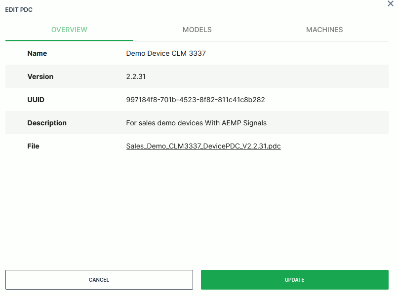
This section specifies the Name of the configuration file. This information is also displayed in the PDC Management of the DataPortal.
Note
This section must be the first item after the header in the configuration file.
<Name xsi:type="MessageDefinition">
  <Label lang="en" value="Example Parsing Definition"/>
  <Label lang="de" value="Beispiel Parsing Definition"/>
</Name>
| Declaration | Description |
|---|---|
lang |
Required is the shortcut of the language. For example, en for English or de for German. |
value |
Equivalent name for the specified language. This name is displayed on the DataPortal in the Machine Overview depending on the language settings of the DataPortal. |
Description
The Description as well as the Name, the UUID and the Version are displayed in the PDC Management of the DataPortal.
<Description xsi:type="MessageDefinition">
  <Label lang="en" value="First Version for PDC Documentation"/>
  <Label lang="de" value="Beispiel Parsing Definition"/>
</Description>
| Attribute | Description |
|---|---|
lang |
Required is the shortcut of the language. For example, en for English or de for German. |
value |
Equivalent name for the specified language. This name is displayed on the DataPortal in the Machine Overview depending on the language settings of the DataPortal. |
Shared Definitions
GlobalDictionary
The predefined keys, individual keys, predefined values and individual values are defined in the Global Dictionary.
These definitions can be used by referencing the Global Dictionary in subsequent parts for displaying individual CAN messages.
All lines within the markers <GlobalDictionary> and </GlobalDictionary> belong to this section.
Each definition starts with <Message> and ends with </Message>.
<GlobalDictionary>
  <Message key="label.value.common.cu.battery.cyclecount">
    <Label lang="en" value="Battery cyclecount modem"/>
    <Label lang="de" value="Batterie Zähler Modem"/>
  </Message>
  <Message key="label.value.common.cu.hours.operation">
    <Label lang="en" value="Operatinghours modem"/>
    <Label lang="de" value="Betriebsstunden Modem"/>
  </Message>
  <Message key="label.value.common.machine.distance.total">
    <Label lang="en" value="Total maschine distance"/>
    <Label lang="de" value="Gesamtkilometerzähler Maschine"/>
  </Message>
  <Message key="label.value.common.machine.hours.idle.total">
    <Label lang="en" value="Operatinghours in idle"/>
    <Label lang="de" value="Betriebsstunden im Leerlauf"/>
  </Message>
  <Message key="label.cond.on">
    <Label lang="en" value="On"/>
    <Label lang="de" value="An"/>
  </Message>
  <Message key="label.cond.off">
    <Label lang="en" value="Off"/>
    <Label lang="de" value="Aus"/>
  </Message>
  <Message key="custom.unit.microAmpere ">
    <Label lang="en" value="uA"/>
  </Message>
</GlobalDictionary>
| Element/ Attribute | Description |
|---|---|
<Message> |
Container for a single dictionary entry. |
key |
A unique identifier. For better readability, use the predefined key schema (label.value.common.[…]) or the custom schema label.value.custom.[…]. For view definitions use label.view.[…]. |
lang |
Language code. Supported values: en, de, zh, cs, da, nl, fr, it, ja, ko, es, sv. |
value |
Display string for the specified language. Shown in the DataPortal depending on the language settings. |
Transformers
Transformers provide the possibility to calculate the correct machine data from the received raw data.
A Transformer is defined between the tags <Transformer> and </Transformer>.
<Transformers>
  <Transformer key="transformer.1.0">
    <formula xsi:type="LinearFormula">
      <scale>1</scale>
      <offset>0</offset>
    </formula>
  </Transformer>
  <Transformer key="transformer.0_125.0">
    <formula xsi:type="LinearFormula">
      <scale>0.125</scale>
      <offset>0</offset>
    </formula>
  </Transformer>
  <Transformer key="transformer.0_5.0">
    <formula xsi:type="LinearFormula">
      <scale>0.5</scale>
      <offset>0</offset>
    </formula>
  </Transformer>
</Transformers>
| Element/Attribute | Description |
|---|---|
<Transformer> |
Container for a single transformer. |
key |
Unique identifier, referenced in <ParsingDefinition>. |
<formula> |
Only linear scaling is supported. |
<scale> |
Multiplication factor for the raw data. |
<offset> |
The offset is added to the result of the multiplication (display value = (raw data × scaling) ± offset). |
The presented value on the DataPortal in the Machine Overview is calculated with a specific Transformer.
Units
Predefined Units
Predefined units are the recommended way on using units for standard metrics, see Units in the Proemion Standard Metrics.
Custom Units
Use custom units only when no matching predefined unit is available.
Warning
Custom units are not supported by Signal Catalog and their usage prevents migration of the PDC. Before defining custom units, consider requesting new standard units via the Service and Support.
The following example illustrates how to use custom units in the PDC.
<Units>
    <Unit key="custom.unit.microAmpere">
        <symbol xsi:type="MessageReference" value="label.custom.unit.microAmpere" />
        <description xsi:type="MessageReference" value="label.custom.unit.microAmpere " />
        <storeType xsi:type="NumericValueStoreType" />
    </Unit>
</Units>
| Element / Attribute | Description |
|---|---|
<Unit> |
Container for a single unit. |
key |
Unique identifier. |
value |
Name of the custom unit in the GlobalDictionary. |
<symbol> |
Reference to the GlobalDictionary, where the unit for displaying on the DataPortal is defined. |
<description> |
Defines an additional description (currently not displayed). |
<storeType> |
Storage type for the signal in the database. Supported values: TextValueStoreType, NumericValueStoreType, BooleanValueStoreType. |
It is recommended to only use store types matching the signal's value type:
TextValueStoreTypeforSeparateCharValueandSimpleCharValuevaluesNumericValueStoreTypeforFloatValueorIntValuevaluesBooleanValueStoreTypeforIntValuevalues that transport boolean (0or1) signals
The DataPlatform data parsing algorithm can cope with all combinations of the unit's store type and the signal's value type.
The following table shows how <storeType> for <Unit> works for different <Values> types in the PDC's <ParsingDefinition>:
| ParsingDefinition Value type | Unit Store type: TextValueStoreType |
Unit Store type: NumericValueStoreType |
Unit Store type: BooleanValueStoreType |
Unit Store type: none (in case of catalog signals) |
|---|---|---|---|---|
SeparateCharValue, SimpleCharValue |
Stored as String. | Stored as Number if parseable from the input string; otherwise not stored. | Stored as Number: 1 for value true, 0 otherwise. |
Stored as Number if parseable from the input string; otherwise stored as String. |
FloatValue, IntValue |
Converted to and stored as String. | Stored as Number. | NumericBooleanFormula evaluated; stored as Number: 1 for true, 0 for false. |
Stored as Number. |
For signals derived from the Signal Catalog and parsed from SeparateCharValue or SimpleCharValue, TextValueStoreType is always used regardless of the unit's store type setting.
Unit Conversion
The DataPortal can convert units from the SI (metric) system to the US system and vice versa. Unit symbols must match the table below exactly for the conversion algorithm to recognize them correctly. It is strongly recommended to use the predefined units described in Predefined Units. The conversion algorithm is not case-sensitive.
| SI (metric) units | Symbol | US units | Symbol |
|---|---|---|---|
| Celsius | oC | Fahrenheit | °F |
| kilogram | kg | pound | lb |
| kilometer | km | miles | mi |
| kilometers per hour | km/h | miles per hour | mp/h |
| kilometers per liter | km/L | miles per gallon | mi/gal |
| kilopascal bar | kPa bar | PSI | psi |
| liter | l | gallon | gal |
| liter per hour | l/h | gallon per hour | gal/h |
| meter | m | foot | ft |
| meter per second | m/s | foot per second | ft/s |
| millimeter | mm | inch | in |
| Newton | N | pound-force | lpf |
| meter per square second | m/s^2 | foot per square second | ft/s^2 |
Signal Definitions
Value Definition
The ValueDefinition defines a signal in DataPlatform by configuring a unique identifier (signal key), a reference to i18n label message key and Units key. A ValueDefinition key can be referenced in the Parsing Definition of CAN-messages.
Note
It is highly advisable to use the Proemion DataPortal Signal Catalog for comparison and unifying the value definition. This enables you to seamlessly analyze machine data across the entire fleet.
Signal Catalog integration
For newly created signals or adapted signals from the Signal Catalog that need to be referenced in the PDC, you must add the following attribute to the <ValueDefinition> element:
managedByDataPlatform="true"
Example:
<ValueDefinition key="value.common.cu.hours.operation" managedByDataPlatform="true"/>
For ValueDefinition elements with managedByDataPlatform="true", no additional child elements or attributes are allowed except key and managedByDataPlatform.
Adding local metadata will result in a validation error during upload to the DataPlatform.
You can find a PDC template including all required elements in PDC Introduction.
ValueDefinition elements without this attribute will be rejected during upload.
For migrating existing signals to the Signal Catalog, see Migration Guide for the Signal Catalog.
Note
If you do not need to define signals, ValueDefinitions may be left empty. It must not be omitted.
<ValueDefinitions/> is a valid element.
ValueDefinitions XML example (DataPlatform and local definitions) (click to view)
<ValueDefinitions>
<!-- Data Platform-managed signal: reference only, no local definition allowed -->
<ValueDefinition key="value.common.cu.hours.operation" managedByDataPlatform="true"/>
    <!-- Locally defined signal -->
    <ValueDefinition key="value.common.cu.battery.cyclecount" managedByDataPlatform="false">
      <description xsi:type="MessageReference"
            value="label.value.common.cu.battery.cyclecount"/>
      <unit>predefined.unit.NUMBER</unit>
    </ValueDefinition>
    <ValueDefinition key="value.common.machine.hours.fullload" managedByDataPlatform="false">
      <description xsi:type="MessageReference"
            value="label.value.common.machine.hours.fullload"/>
      <unit>predefined.unit.time.HOUR</unit>
    </ValueDefinition>
    <ValueDefinition key="value.common.engine.fuel.efficiency.total" managedByDataPlatform="false">
      <description xsi:type="MessageReference"
            value="label.value.common.engine.fuel.efficiency.total"/>
      <unit>predefined.unit.flow.LITER_PER_HOUR</unit>
      <format>%.2f</format>
    </ValueDefinition>
    <ValueDefinition key="value.common.engine.speed" managedByDataPlatform="false">
      <description xsi:type="MessageReference"
            value="label.value.common.engine.speed"/>
      <unit>predefined.unit.rotation.RPM</unit>
    </ValueDefinition>
    <ValueDefinition key="value.common.machine.distance.total" managedByDataPlatform="false">
      <description xsi:type="MessageReference"
            value="label.value.common.machine.distance.total"/>
      <unit>predefined.unit.length.KILOMETER</unit>
      <format>%.0f</format>
      <categories>
           <category xsi:type="Counter"/>
        </categories>
    </ValueDefinition>
    <ValueDefinition key="value.common.engine.def.level" managedByDataPlatform="false">
      <description xsi:type="MessageReference"
            value="label.value.common.engine.def.level"/>
      <unit>predefined.unit.PERCENT</unit>
    </ValueDefinition>
    <ValueDefinition key="value.common.engine.fuel.level" managedByDataPlatform="false">
      <description xsi:type="MessageReference"
            value="label.value.common.engine.fuel.level"/>
      <unit>predefined.unit.PERCENT</unit>
      <format>%1.0f</format>
      <minValue>0</minValue>
      <maxValue>100</maxValue>
    </ValueDefinition>
    <ValueDefinition key="value.common.model.fuel.efficiency.total" boundTo="model" managedByDataPlatform="false">
      <description xsi:type="MessageReference"
            value="label.value.common.model.fuel.efficiency.total"/>
      <unit>predefined.unit.flow.LITER_PER_HOUR</unit>
      <format>%.2f</format>
    </ValueDefinition>
    <ValueDefinition key="value.common.machine.hours.operation.total" managedByDataPlatform="false">
      <description xsi:type="MessageReference"
            value="label.value.common.machine.hours.operation.total"/>
      <unit>predefined.unit.time.HOUR</unit>
      <format>%1.1f</format>
      <categories>
        <category xsi:type="Counter" decreasing="false"/>
      </categories>
    </ValueDefinition>
    <ValueDefinition key="value.EngineHighTemp" managedByDataPlatform="false">
            <description xsi:type="MessageReference"
            value="label.value.EngineHighTemp"/>
            <unit>unit.state</unit>
            <categories>
                <category xsi:type="StateSignal" subType="boolean" machineError="true">
                    <state>
                        <description xsi:type="MessageReference"
            value="label.value.EngineHighTemp.On"/>
                        <aempCautionCode>
                            <Identifier>ISO 7000-1167</Identifier>
                            <Description>Transmission oil-pressure</Description>
                        </aempCautionCode>
                    </state>
                    <state value="0" inactive="true">
                        <description xsi:type="MessageReference"
            value="label.value.EngineHighTemp.Off"/>
                    </state>
                </category>
            </categories>
        </ValueDefinition>
        <ValueDefinition key="value.EngineLowTemp" managedByDataPlatform="false">
            <description xsi:type="MessageReference"
            value="label.value.EngineLowTemp"/>
            <unit>unit.state</unit>
            <categories>
                <category xsi:type="StateSignal" subType="enumeration" machineError="true">
                    <state value="1" inactive="true" >
                        <description xsi:type="MessageReference"
            value="label.value.EngineLowTemp.State_1"/>
                    </state>
                    <state value="2">
                        <description xsi:type="MessageReference"
            value="label.value.EngineLowTemp.State_2"/>
                    </state>
                    <state value="3">
                        <description xsi:type="MessageReference"
            value="label.value.EngineLowTemp.State_3"/>
                    </state>
                </category>
            </categories>
        </ValueDefinition>
  </ValueDefinitions>
| Element/Attribute | Description |
|---|---|
<ValueDefinition> |
Collector for a "ValueDefinition” |
<ValueDefinition>.key |
Defines the signal key |
<ValueDefinition>.managedByDataPlatform |
If value is true, the value definition from the DataPlatform Signal Catalog is used. The attribute must be added to the <ValueDefinition> element. Only key and managedByDataPlatform are allowed. |
<description> |
Defines the label |
<description>.value |
References the key of a |
<unit> |
Assigns the signal to a custom Unit or a predefined Unit. |
<format> |
Optional. Defines the formatting of the values displayed in the DataPortal. This setting applies if no settings are made in the DataPortal. The system saves all numerical values as high-precision floating point numbers. Example: %1.2f ("f" stands for float and 1.2 defines the representation with 1 pre-decimal place and 2 decimal places). The definition of the digits before the decimal point is optional. If no pre-decimal places are defined, all pre-decimal places are displayed (example: %.0f). In case that the representation of the predefined.unit.time.HOUR needs to be switched from HH:MM:SS to HH, the format <format>%1.0f</format> must be defined. Otherwise, the default format HH:MM:SS will be used. |
<minValue> |
The ability to define the minimum value of a signal and therefore correctly scale visualizations, such as plots. |
<maxValue> |
The ability to define the maximum value of a signal therefore correctly scale visualizations, such as plots. |
<categories> |
The tag <category>. |
<category> |
The properties of the signal can be defined using <category>. |
<category>.type |
The attribute "xsi:type" defines the type of signal. Two values are currently supported: |
| "Counter": The delta query can then be used in the data portal and on the REST-API for signals that contain these attributes. Counter signal only has the *decreasing | |
"StateSignal": Allows the definition of caution codes on the AEMP interface (<aempCautionCode>). Can select from 2 subtypes "boolean"(0,1) and "enumeration" (0,1,2,3...). |
|
<category>.subType |
The attribute "xsi:subType" defines the sub type for state signals. Two values are currently supported: |
| "boolean": Allows to define a mapping for a signal with two states | |
| "enumeration": Allows to define a mapping for a signal with multiple states | |
<category>.machineError |
|
| "true": Values of this signal will be part of the AEMP caution code endpoint. The signal value will be used as caution code identifier. The label as caution code description. | |
| "false": Values of this signal will NOT be part of the AEMP caution code endpoint. | |
<category>.<aempCautionCode> |
Container for <Description> and <Identifier>.Is used as a source for the standard metrics CautionMessages, see Caution Codes. |
If <aempCautionCode> is absent, then the <state>.value and <state>.description are used. |
|
<Identifier> refers to the caution code reference number ISO 7000 or IEC 60417 which represents the registration number of the symbol displayed on the machine indicating a system problem that occurred at a specific data and time. In turn, the symbol registration number refers to "ISO 6405-1" and "ISO 6405-2". The <Identifier> is optional and is a string with unbounded length. Defining this element allows to use a standard regarding alerts. |
|
<category>.<state> |
Allows the definition of a state per value. |
<state>.value |
The signal value representing a specific state |
<state>.inactive |
|
| "true": Non-error state, will NOT be part of AEMP caution code endpoint. | |
| false": Error state, will be part of AEMP caution code endpoint. | |
<state>.<description> |
Defines the label, see above. |
<ValueDefinition>.boundTo |
If signals do not specifically belong to a machine, but are determined based on a model, the boundTo attribute should be used. This indicates that a signal is provided by the model of a machine and not directly by the machine itself. You can choose between the "machine" and "model" key, with machine being the default case. NOTE: The signal is not automatically filled when creating the value definition. In many cases special scripts are required to fill the signals with values. To do so, you will have to contact Proemion. NOTE: If boundTo = "model" is used, the value definition key must contain the following syntax: value [common\|custom].model.\.*. |
J1939 Diagnostic Message Parsing
This section covers how the PDC parses J1939 Diagnostic Messages (DM1, DM2, DM53) and custom error protocols.
The <DM1_DM2Message> element in <BinaryStreamDefinition> selects the parsing behaviour via the conversionMode attribute.
The Diagnostic Messages (DM) will be transmitted in CAN messages. The Proemion system interprets these CAN messages in the PDC.
To interpret the correct arrangement in the SPN, choose the SPN Conversion Method according to your engine or ECU datasheet.
Support of DM1 and DM2 for DTCs
DataPlatform DM1 and DM2 behaviour
DM1 messages contain a list of DTCs currently active on the machine. DTCs present in the message that are not already known as active are stored as newly active DTCs in the DataPlatform. Already known active DTCs are ignored. DTCs currently active in the DataPlatform but absent from a newly received DM1 message are deactivated. An empty DM1 message closes all active DTCs.
DM2 messages contain previously active DTCs. On the DataPlatform these messages are used for closing potentially active DTCs. If a currently active DTC is present in the DM2 message, it is deactivated. Currently, there is no other function for DM2 messages.
The following example shows how messages for DM1_DM2 will be implemented in the PDC.
The channel number defined in the <BinaryStreamDefinition> is used as the designator for the matching <DM1_DM2Message> or <CanMessage> received at the DataPlatform.
The channel number must match the receiving CAN message.
It is recommended to define CAN message parsing for each channel separately instead of using a combination of channel-agnostic and channel-specific <BinaryStreamDefinition> elements.
If there is no matching <DM1_DM2Message> or <CanMessage> for a message on a configured channel, the message will not be parsed.
PDC configuration
<!-- ParsingDefinition -->
  <ParsingDefinition>
    <BinaryStreamDefinition src="CAN" channel="1">
      <CanMessage canId="0x101" canIdLength="11" mask="0x7FF" protocolStyle="GENERIC"> [18 lines]
      <CanMessage canId="0x102" canIdLength="11" mask="0x7FF" protocolStyle="GENERIC">
        ...
      </CanMessage>
      <DM1_DM2Message conversionMode="2" sourceAddress="0x83" readLampStatus="false"/>
      <DM1_DM2Message conversionMode="1"/>
    </BinaryStreamDefinition>
  </ParsingDefinition>
| Element/Attribute | Description |
|---|---|
<DM1_DM2Message> |
DM1 — Active Diagnostic Trouble Codes. DM2 — Previously Active Diagnostic Trouble Codes. |
<DM53_Message> |
Active Service Only DTCs. |
conversionMode |
Specifies the SPN conversion method. Valid values: 1–4 (standard J1939), 100 (DTC as UINT32), 101 (custom error protocol). |
sourceAddress |
Optional. If set, the conversion mode is used only for this address. If not set, all addresses use the same conversion mode. |
readLampStatus |
If set to false, the lamp status value is not read from the J1939 DM1/2 messages. If no lamp status is available in the database, the lamp status will not be displayed in the DataPortal views and widgets. |
Support of DM53 Messages for DTCs
The Diagnostic Message DM53 is used for Active Service Only DTCs (DM53). It is a subset of DM1_DM2Message and shows actual DTCs, not only the available diagnostic messages.
PDC configuration
<ParsingDefinition>
    <BinaryStreamDefinition src="CAN">
        <DM53Message conversionMode="1" sourceAddress="0x34"/>
    </BinaryStreamDefinition>
</ParsingDefinition>
For DM53, the same conversionMode values are valid as for DM1: 1, 2, 3, and 4.
Standard Conversion Modes (1–4)
Standard conversion modes define how the SPN field is interpreted within a J1939 DM1/DM2 message. Choose the mode according to the engine or ECU datasheet.
The four standard conversion methods are illustrated in the figures below.
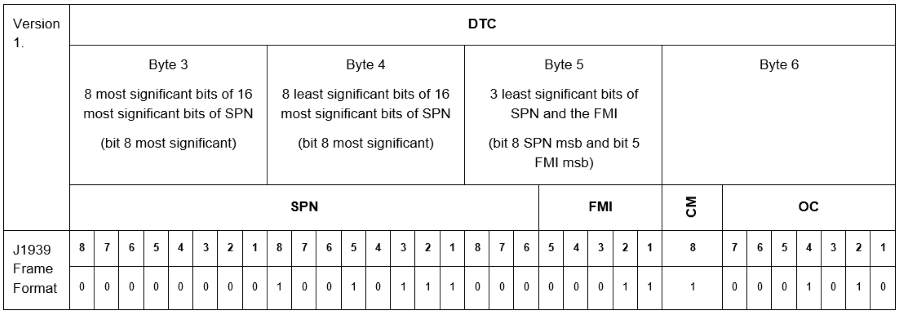
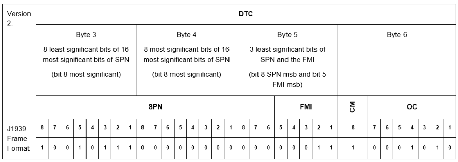
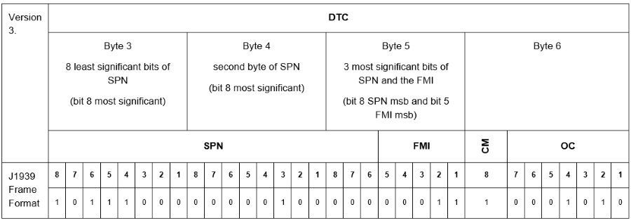
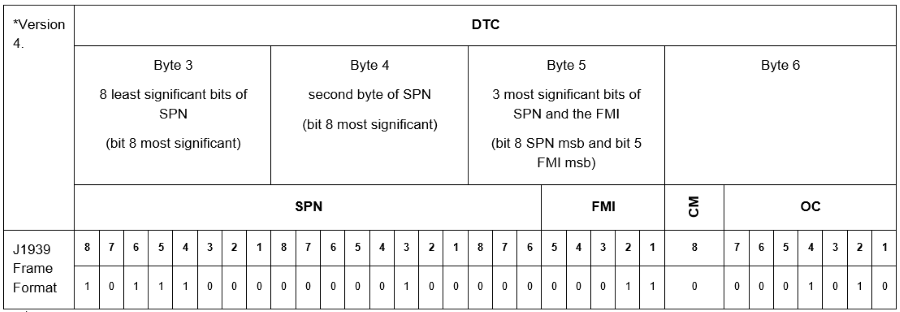
If the CM-Bit (Conversion Method) is set to 1 in the CAN message, indicate the relevant conversion method (Version 1 to 3) at conversionMode=" ".
If the CM-Bit is set to 0, Version 4 is set by default and the PDC setting is ignored.
Conversion modes 3 and 4 are identical — the CAN messages are interpreted in the same manner. The difference is that mode 4 is used automatically while mode 3 can be set manually. Using mode 3 instead of mode 4 produces no error when checking the PDC.
Proprietary Conversion Modes
Mode 100 — DTC as UINT32
In conversion mode 100, every 4-byte DM1 DTC block is interpreted as a UINT32 number and set as the SPN ID. FMI defaults to 0. If FMI must be derived from a lookup file, contact customer care.
Mode 101 — Custom Error Protocol
Conversion mode 101 is a proprietary extension for machines that transmit errors in a custom CAN format that cannot be mapped to standard J1939 DM1 — for example when the priority field exceeds the 5-bit FMI limit of the J1939 standard.
The controller application sends a snapshot of all currently active errors as a sequence of 6-byte entries under the J1939 DM1 PGN (0xFECA).
Each entry maps to J1939 fields as follows:
| Field | Maps to | Data type | Size | Byte order |
|---|---|---|---|---|
LOCATION |
Source address | UINT16 | 2 bytes | LSB first (byte 0) |
Type |
SPN ID | UINT16 | 2 bytes | LSB first (byte 0) |
PRIORITY |
FMI ID | UINT16 | 2 bytes | LSB first (byte 0) |
The payload structure for multiple active errors:
| ERROR 1                       | ERROR 2                       | ... | ERROR n                       |
| LOCATION | Type   | PRIORITY  | LOCATION | Type   | PRIORITY  | ... | LOCATION | Type   | PRIORITY  |
| 2 bytes  | 2 bytes| 2 bytes   | 2 bytes  | 2 bytes| 2 bytes   | ... | 2 bytes  | 2 bytes| 2 bytes   |
All values are unsigned integers. Empty bytes are not padded with 0xFF.
Up to 256 errors can be transmitted per message.
All errors share the same J1939 source address. Lamp status is not transmitted.
When no errors are active, the controller sends a single entry with all fields set to 0, following the J1939 DM1 convention for signalling an empty error list.
Warning
A resolved subset of errors cannot be identified from the CAN message alone. The no-error entry (LOCATION = 0, Type = 0, PRIORITY = 0) only appears after all active errors have been resolved.
PDC configuration
<ParsingDefinition>
  <BinaryStreamDefinition src="CAN">
    <DM1_DM2Message conversionMode="101" sourceAddress="0x80" readLampStatus="false"/>
  </BinaryStreamDefinition>
</ParsingDefinition>
The LOCATION, Type, and PRIORITY fields map to J1939 source address, SPN, and FMI respectively. Default J1939 labels can be overridden using <SourceLabelOverrides>, <SpnLabelOverrides>, and <FmiLabelOverrides>. See J1939 Label Overrides below.
J1939 Label Overrides
To display J1939 error codes (source address, SPN, and FMI) as text in the DataPortal, add the following lines to the PDC immediately before the <Unit> tag.
<J1939>
  <xi:include href="https://xml.proemion.com/ProemionDataConfiguration/J1939_202503_SpnLabels.xml"/>
</J1939>
It is possible to override the default J1939 texts for source address, SPN, and FMI with custom labels. Add the following lines to your PDC.
The content of the value attribute can be defined freely.
<!-- J1939 -->
<J1939>
  <xi:include href="https://xml.proemion.com/ProemionDataConfiguration/J1939_202503_SpnLabels.xml"/>
  <SpnLabelOverrides>
    <Spn id="6">
      <message>
        <Label lang="fr" value="My new SPN 6"/>
      </message>
    </Spn>
    <Spn id="7" forSourceAddress="7">
      <message>
        <Label lang="fr" value="My new SPN 7"/>
      </message>
    </Spn>
  </SpnLabelOverrides>
  <FmiLabelOverrides>
    <Fmi code="13" forSourceAddress="12">
      <message>
        <Label lang="en" value="My new FMI 13"/>
      </message>
    </Fmi>
    <Fmi code="14">
      <message>
        <Label lang="en" value="My new FMI 14"/>
      </message>
    </Fmi>
  </FmiLabelOverrides>
  <SourceLabelOverrides>
    <Source address="1">
      <message>
        <Label lang="de" value="My new Source 1"/>
      </message>
    </Source>
    <Source address="2">
      <message>
        <Label lang="de" value="My new Source 2"/>
      </message>
    </Source>
  </SourceLabelOverrides>
</J1939>
| Element/Attribute | Description |
|---|---|
<SpnLabelOverrides> |
Overrides the standard label for a Suspect Parameter Number (SPN). |
Spn |
Defines that a SPN label should be changed. |
id |
Defines which SPN should be relabelled. |
lang |
Language code for the label. Depending on the DataPortal language settings the equivalent value is displayed. |
value |
Replacement label for the specified language. |
forSourceAddress |
Optional. Restricts the override to a specific source address. |
<FmiLabelOverrides> |
Overrides the standard label for a Failure Mode Identifier (FMI). |
Fmi |
Defines that an FMI label should be changed. |
code |
Defines which FMI code should be relabelled. |
<SourceLabelOverrides> |
Overrides the standard label for a source address (typically an ECU). |
address |
Defines the source address to be relabelled. |
Parsing Definition
The ParsingDefinition is the actual evaluation of a CAN message. This setting is made for each value depending on the CAN message. This definition allows the specification according to the location of a signal (e.g. Torque) within a CAN message.
ParsingDefinition XML example (click to view)
<ParsingDefinition>
    <BinaryStreamDefinition src="CAN">
      <CanMessage canId="0x100F11FF" canIdLength="29" mask="0x1FFFFFFF" protocolStyle="GENERIC">
        <Values>
          <IntValue startPos="0" length="8" endianness="LITTLE" signed="false" continueOnLastPostion="false">
            <valueDefinition ref="value.common.machine.distance.total"/>
            <transformer ref="transformer.1.0"/>
          </IntValue>
        </Values>
      </CanMessage>
      <CanMessage canId="0x12F003F0" canIdLength="29" mask="0x1FFFFFFF" protocolStyle="GENERIC">
        <Values>
          <IntValue startPos="0" length="8" endianness="LITTLE" signed="false" continueOnLastPostion="false">
            <valueDefinition ref="value.common.cu.battery.cyclecount"/>
            <transformer ref="transformer.1.0"/>
          </IntValue>
        </Values>
      </CanMessage>
      <CanMessage canId="0x18F00400" canIdLength="29" mask="0x1FFFFFFF" protocolStyle="GENERIC">
        <Values>
          <IntValue startPos="24" length="16" endianness="LITTLE" signed="false" continueOnLastPostion="false">
            <valueDefinition ref="value.common.engine.speed"/>
            <transformer ref="transformer.0_125.0"/>
          </IntValue>
        </Values>
      </CanMessage>
      <CanMessage canId="0x1FA" canIdLength="11" mask="0x7FF" protocolStyle="GENERIC">
        <Values>
          <IntValue startPos="0" length="8" endianness="LITTLE" signed="false" continueOnLastPostion="false">
            <valueDefinition ref="value.common.engine.def.level"/>
            <transformer ref="transformer.1.0"/>
          </IntValue>
        </Values>
      </CanMessage>
      <CanMessage canId="0x2A0" canIdLength="11" mask="0x7FF" protocolStyle="GENERIC">
        <Values>
          <IntValue startPos="8" length="16" endianness="LITTLE" signed="false" continueOnLastPostion="false">
            <valueDefinition ref="value.common.machine.hours.fullload"/>
            <transformer ref="transformer.1.0"/>
          </IntValue>
        </Values>
      </CanMessage>
      <CanMessage canId="0x7FA" canIdLength="11" mask="0x7FF" protocolStyle="GENERIC">
        <Values>
          <SeparatedCharValue charset="US-ASCII" separator="*">
            <CharValue column="0">
              <valueDefinition ref="value.String1"/>
            </CharValue>
            <CharValue column="1">
              <valueDefinition ref="value.String2"/>
            </CharValue>
            <CharValue column="3">
              <valueDefinition ref="value.String3"/>
            </CharValue>
            <CharValue column="4">
              <valueDefinition ref="value.String4"/>
            </CharValue>
          </SeparatedCharValue>
        </Values>
      </CanMessage>
      <CanMessage canId="0x100" canIdLength="11" mask="0x7FF" protocolStyle="GENERIC">
        <Values>
          <SimpleCharValue startPos="0" charset="UTF-8" continueOnLastPostion="false">
            <valueDefinition ref="value.tail"/>
              <length type="CHAR" value="20"/>
          </SimpleCharValue>
        </Values>
      </CanMessage>
      <CanMessage canId="0x123" canIdLength="11" mask="0x7FF" protocolStyle="GENERIC">
        <Values>
          <DtcValue startPos="7" continueOnLastPostion="false">
            <Spn id="517111"/>
            <Fmi code="33"/>
            <Source address="254"/>
          </DtcValue>
          <DtcValue startPos="6" continueOnLastPostion="false">
            <Spn id="517111"/>
            <Fmi code="34"/>
            <Source address="254"/>
          </DtcValue>
          <DtcValue startPos="5" continueOnLastPostion="false">
            <Spn id="517111"/>
            <Fmi code="35"/>
            <Source address="254"/>
          </DtcValue>
        </Values>
      </CanMessage>
    </BinaryStreamDefinition>
  </ParsingDefinition>
Parsing Definition Specification
| Element/Attribute | Description |
|---|---|
<BinaryStreamDefinition> |
Indicates the Source of a message. |
src |
Currently only supports CAN. |
channel |
Optional: If channel is not specified, the IDs are evaluated independently of the channel specification. If a channel is specified, then all messages from this channel will be evaluated exclusively in this binary stream definition and no longer in a binary stream definition that has no channel specified. Therefore, it is recommended to always use the channel attribute. Read also the note in J1939 Diagnostic Message Parsing. |
| "1" = CAN-Interface 1 "2" = CAN-Interface 2 "3" = Internal logging (Data transmitted by the operation manager) "4" = CAN3-Interface 3 |
|
<CanMessage> |
Defines which CAN message is evaluated. |
canId |
Specifies the exact identity of the CAN message (e.g.: 11bit → 0x7FF; 29bit → 0x1FFFFFFF). |
canIdLength |
Specifies the length of the CAN-message (11Bit or 29bit). |
mask |
Filter for the ID (e.g. 0x1FFFFFFF only receives exactly the specified ID). |
protocolStyle |
Currently, only supports GENERIC. |
ignoreJ1939InvalidData |
Optional: If this attribute is set to true, the values for the respective signals (which have all bits = 1) are ignored and not stored in the database.Example: The value of an integer with 8 bits ( 0b11111111 = 0xFF) is not saved. If this attribute is set to false or is not specified, all values are saved. |
allowMissingValues |
When set to true (i.e. the default, also when the attribute is not set), the actual CAN message is allowed to contain fewer values than configured in PDC - any missing value will be silently skipped. When set to false, an entire CAN message with missing values will be discarded (in order to control a strict CLF parsing). |
<Values> |
Represents the area in which the signals are defined in the message. |
<IntValue> |
Indicates that it is an integer value (also <FloatValue> is possible).PDC – Value Length Restrictions When reading CAN message data, the following restrictions apply regarding bit length and bit position: Supported definitions: - Bit lengths of 8, 16, 24, or 32 bits, provided they are byte-aligned ( startPos = 0, 8, 16, 24, …).- Bit lengths of 1 to 7 bits, provided the signal is fully located within a single byte (e.g. startPos="5" and length="3").For these cases, a special startPos must be calculated, see note below for an calculation example.Unsupported definitions: - Any startPos / length combinations that span more than one byte but do not occupy all bits of the affected bytes (e.g. startPos="40" and length="12"). |
startPos |
Specifies the start position of the signal in the message. |
length |
Specifies the length of the signal in bits. The attribute is optional for SimpleCharValue and if not given all bytes till the end of the stream are read for the value. |
endianness |
Specifies the byte sequence of the signal. Allowed values: LITTLE → LSB first (least significant bit), BIG → MSB first (most significant bit). BIG is the default. |
signed |
Specifies whether the data received is signed. Allowed values: true, false (default). |
continueOnLastPostion |
Defaults to true, which implies that startPos starts from the end of the prior value. MUST be set to false for absolute positioning. |
<valueDefinition> |
Reference to a ValueDefinition defining the signal key used to store the parsing result in DataPlatform. |
<Transformer> |
Reference to transformer definition. |
<SeparatedCharValue> |
Represents the area in which the properties of the string to be saved are defined. |
requireAllValuesPresent |
Optional flag that allows for partial multi-value string matches for the <SeparatedCharValue> node. |
charset |
Defines the character encoding to be used to store the string. Defaults to US-ASCII for SeparatedCharValue and SimpleCharValue |
startPos |
Specifies the position from where the string is to be stored, starting with "0". |
separator |
Defines the separator of the string, the default value is *. The separator makes only sense when the sourceType is ASCII. The values can then be a set of multiple strings separated by the specified separator. |
<CharValue> |
Opens the dropping of a string, taking into account the specified separator, into the variable of the ValueDefinition. |
column |
Defines the column in which the string to be stored is located. |
<SimpleCharValue> |
Represents the area in which the properties of a simple character or string to be saved are defined. |
type |
Defines the type of the char. Possible values are char or byte. |
value |
Defines the length of the char. The default value is 1. |
DtcValue |
This option allows configuration of bit coded DTC messages. Each Bit represents one DTC error. The Source, SPN and FMI will be replaced according to the customer specific DTC labels in chapter J1939 Diagnostic Message Parsing table J1939 Value Specification. |
Calculation of startPos for sub-byte signals (1–7 bit)
For signals with a bit length of 1 to 7 bits that are fully located within a single CAN byte, the startPos is calculated using a linear bit index:
startPos = (byteIndex × 8) + bitOffset, where byteIndex is the zero-based index of the byte within the CAN message (first byte = 0) and bitOffset is the zero-based bit position within the byte (LSB = 0, MSB = 7).
Example:
A signal located in byte 1 (second byte), with a bit offset of 2 and a bit length of 2, results in startPos = (1 × 8) + 2 = 10, therefore the corresponding PDC configuration is startPos="10" and length="2".
Special Case: Relaxed Parsing
CAN message values are parsed according to the definition in the PDC. By default values not matching the definition are ignored. The default is different for <SimpleCharValue>. There, if the corresponding part of the CLF message is split on a different number of values than defined in the PDC, then all values are ignored.
In some cases you may want to extract as many values as defined in the PDC. That requires the requireAllValuesPresent flag to be set false on <SeparatedCharValue> node.
Setting the requireAllValuesPresent flag to false for the <SeparatedCharValue> node will read just the available values with the available definition and ignore the missing ones. See the example code snippet below.
 <CanMessage canId="0x7FA" canIdLength="11" mask="0x7FF" protocolStyle="GENERIC">
        <Values>
          <SeparatedCharValue requireAllValuesPresent="false">
            <CharValue column="0">
              <valueDefinition ref="value.string" />
            </CharValue>
            <CharValue column="1">
              <valueDefinition ref="value.string1.ext" />
            </CharValue>
            <!-- NEW V02.00.00 -->
            <CharValue column="2">
              <valueDefinition ref="value.string2.ext" />
            </CharValue>
            <!-- NEW V02.00.00 -->
            <CharValue column="3">
              <valueDefinition ref="value.string3.ext" />
            </CharValue>
          </SeparatedCharValue>
        </Values>
    </CanMessage>
View Definition
Warning
The ViewDefinition is deprecated and not suitable or required for use in DataPortal!
As the PDC schema does not require the presence of the ViewDefinitions tag, you may completely omit it.
Actions
An Action allows the user to trigger a configured function on a machine via the DataPortal or Rest API by sending numeric and float values, as well as strings, to the device. For example, they can reset the service counter or prevent the machine from restarting. To use the Action, <Actions> must be inserted after the <ValueDefinition>. Please also refer to Permissions. It must be defined which permissions are valid for the Action. The usage of <Actions> is optional.
ActionDefinition XML example (click to view)
<!-- ActionDefinition -->
  <Actions>
    <SetNumericValueActions>
      <action key="ServiceCounter">
        <objectDictionary index="0x4006" subIndex="0x02"/>
        <title xsi:type="MessageReference" value="label.action.title.service.counter.reset"/>
        <description xsi:type="MessageReference" value="label.action.description.service.counter.reset"/>
        <valueLabel xsi:type="MessageReference" value="label.action.value.service.counter.reset"/>
        <valueDefinition ref="value.common.machine.service.hourstonextservice"/>
        <validations>
          <valueRange min="0" max="1000"/>
        </validations>
      </action>
      <action key="FastLoggingMode">
        <objectDictionary index="0x4002" subIndex="0x05"/>
        <title xsi:type="MessageReference" value="label.action.title.fastloggingmode "/>
        <description xsi:type="MessageReference" value="label.action.description.fastloggingmode "/>
        <valueLabel xsi:type="MessageReference" value="label.action.value.fastloggingmode "/>
        <valueDefinition ref="value.custom.diagnostic.status"/>
        <validations>
          <discreteValues>
            <discreteValue value="0">
              <valueLabel xsi:type="MessageReference" value="label.action.fastloggingmode.deactivate "/>
            </discreteValue>
            <discreteValue value="1">
              <valueLabel xsi:type="MessageReference" value="label.action.fastloggingmode.activate "/>
            </discreteValue>
          </discreteValues>
        </validations>
      </action>
      <action key="PGrade">
        <objectDictionary index="0x1234" subIndex="0x32"/>
        <title xsi:type="MessageReference" value="label.action.title.p.grade"/>
        <description xsi:type="MessageReference" value="label.action.description.p.grade"/>
        <valueLabel xsi:type="MessageReference" value="label.action.value.p.grade"/>
        <valueDefinition ref="value.common.p.grade"/>
         <type value="float"/>
        <validations>
          <valueRange min="0.01" max="0.9"/>
        </validations>
      </action>
    </SetNumericValueActions>
    <SetStringValueActions>
      <action key="Bluetooth">
        <objectDictionary index="0x999" subIndex="0x05"/>
        <title xsi:type="MessageReference" value="label.action.title.bluetooth.name"/>
        <description xsi:type="MessageReference" value="label.action.description.bluetooth.name"/>
        <valueLabel xsi:type="MessageReference" value="label.action.value.bluetooth.name"/>
        <valueDefinition ref="value.common.bluetooth.name"/>
        <validations>
          <valueLength min="0" max="100"/>
        </validations>
      </action>
    </SetStringValueActions>
  </Actions>
The UUID and customerVersion are displayed in the PDC Management of the DataPortal.
| Element/Attribute | Declaration |
|---|---|
<Actions> |
Opens the area in which actions can be defined. |
<SetNumericValueActions> |
Specifies that subsequent actions based on numeric values are defined (currently only numeric is supported). |
<action> |
Defines the name of the |
<objectDictionary> |
Definition of the variable in the device object dictionary, which will be written to the device. Index and subindex can be taken from the "Value type:" field in the Proemion Configurator. |
<title> |
Reference to the message in the "GlobalDictionary" in which the displayed name of the action in the portal is defined. |
<description> |
Reference to the message in the "GlobalDictionary" that defines the text of the action description. |
<valueLabel> |
Reference to the message in the "GlobalDictionary" that specifies the text in the input field of the action. |
<valueDefinition> |
[optional] Reference to the signal in the "ValueDefinition". If added, the current value of the signal listed is displayed in the Action UI. |
<validations> |
Opens the area in which the value interval to be transmitted is defined. |
<discreteValues> |
Opens the area in which a dropdown menu can be defined. |
<discreteValue> |
The <discreteValue> tag assigns a corresponding numeric value to the text in the dropdown menu. It is transferred when selecting the option. |
<valueRange> |
The <valueRange> defines the values of the interval. With min="x" and max ="y" the lower and upper limit is defined. The values are to be entered in integer format. |
<SetStringValueActions> |
Opens the area where strings for subsequent actions are defined. |
<Label> |
Defines the name of the respective action. |
lang |
This key, within <Label>, determines the language of the label. Examples are de for German and en for English. |
value |
The respective string is assigned to the label via the key. |
<valueLength> |
The <valueLength> defines the length of the string to be stored. With min="x" and max ="y" the lower and upper limit is defined. The values are to be entered in integer format. |
type |
Defines with the key value="float" that it can use floating point numbers for this action. "Value" can take the values integer and float. Integer is the default value. |
Permissions
Permissions provides the possibility to make values and actions accessible or inaccessible to different user groups.
By implication, it can be defined which organization types (labels on the organization in the DataPortal) can see which signals or actions.
Signals, DTCs and Actions without allocation can be viewed by all users.
Permissions must be defined in the following order: <SignalPermissions>, <J1939Permissions>, <GeoPermissions>, <ActionPermissions>.
Note
If the <j1939Permissions> is not defined, all DTCs will be visible for all users.
Consider that the PDC is assigned to machines or models and, therefore, permissions are applied on a machine or model level.
<Permissions>
    <SignalPermissions>
      <valueDefinition ref="value.common.engine.fuel.level">
        <visibleToOrganizationTypes>
          <type>OEM</type>
          <type>Dealer</type>
          <type>Machine_Owner</type>
        </visibleToOrganizationTypes>
      </valueDefinition>
      <valueDefinition ref="value.common.engine.speed">
      <visibleToOrganizationTypes>
          <type>OEM</type>
          <type>Distributor</type>
          <type>Machine_Owner</type>
        </visibleToOrganizationTypes>
      </valueDefinition>
    </SignalPermissions>
    <J1939Permissions>
        <source address="20">
          <spn id="12">
            <visibleToOrganizationTypes>
              <type>Dealer</type>
            </visibleToOrganizationTypes>
          </spn>
            <spnRange minimalId="14" maximalId="18">
                <visibleToOrganizationTypes>
                    <type>Distributor</type>
                </visibleToOrganizationTypes>
            </spnRange>
        </source>
        <sourceRange minimalAddress="20" maximalAddress="23">
            <visibleToOrganizationTypes>
                <type>OEM</type>
            </visibleToOrganizationTypes>
            <spn id="12">
                <visibleToOrganizationTypes>
                    <type>Machine_Owner</type>
                </visibleToOrganizationTypes>
            </spn>
        </sourceRange>
    </J1939Permissions>
    <GeoPermissions>
      <visibleToOrganizationTypes>
        <type>Dealer</type>
        <type>Machine_Owner</type>
      </visibleToOrganizationTypes>
    </GeoPermissions>
    <ActionPermissions>
      <action ref="ServiceCounter">
        <visibleToOrganizationTypes>
          <type>Dealer</type>
          <type>Machine_Owner</type>
          <type>OEM</type>
        </visibleToOrganizationTypes>
        <permissionSets>
          <permissionSet subject="Machine" minimalLevel="View"/>
        </permissionSets>
      </action>
    </ActionPermissions>
</Permissions>
| Element/Attribute | Declaration |
|---|---|
<SignalPermissions> |
Definition of the signals for which authorizations are to be created. Consider also Proemion-only Signals. |
<valueDefinition> |
Reference to the signal key in the ValueDefinition. |
<visibleToOrganizationTypes> |
Definition of the authorizations for the signal previously addressed in the |
<type> |
Specifies the organization unit that is to receive the authorization. |
| The following organization units are currently supported. | |
| OEM | |
| Dealer | |
| Distributor | |
| Machine_Owner | |
<GeoPermissions> |
Definition of the authorizations for the GPS signals. |
<ActionPermissions> |
Opens the area in which the permissions for actions are defined. |
<action> |
Reference to the action for which authorizations are to be created. |
<permissionSets> |
Opens the area in which the authorization group is defined. |
<permissionSet> |
Determines for which group the authorization is created and what the minimum level of the authorization is. |
| Currently the following subjects: | |
Assignment |
|
AEMP |
|
Contract |
|
Dashboard |
|
Location |
|
Machine |
|
Model |
|
Organization |
|
Report |
|
Task |
|
Tenant |
|
Theme |
|
| and levels are supported: | |
View |
|
Maintain |
|
Administer |
|
Latest |
|
History |
|
| Consider that not all possible subject-level combinations are valid. Please refer to DataPortal User Manual → Permissions for reference. | |
<J1939Permissions> |
Opens the area where the permissions for DTCs can be created. |
<source> |
Opens the area in which permissions are created for a DTC based on its address. The value of the address is given in decimal. |
<spn> |
Opens the area in which permissions can be defined for SPNs The respective SPN is addressed via the key "id". |
<sourceRange> |
Opens the area in which permissions for DTCs are created based on an address range. This is done using the syntax <sourceRange minimalAddress="xx" maximalAddress="yy">. Overlaps in ranges are not permitted. |
<spnRange> |
Opens the area where permissions can be defined for a range of SPNs. The respective range is defined using the syntax <spnRange minimalId="xx" maximalId="yy">. Overlaps in ranges are not permitted. |
Proemion-only Signals
If you need to remove permissions for all organizations, you can remove the complete list of organization types for each signal key reference in the ValueDefinition.
As Proemion always has access/permissions to any signal; adding an empty <visibleToOrganizationTypes>, implies a signal visible to Proemion only:
<Permissions>
    <SignalPermissions>
        <valueDefinition ref="value.acc.x">
            <visibleToOrganizationTypes>
            </visibleToOrganizationTypes>
        </valueDefinition>
    </SignalPermissions>
</Permissions>
Listing only Proemion behaves the same as an empty <visibleToOrganizationTypes>:
<visibleToOrganizationTypes>
    <type>Proemion</type>
</visibleToOrganizationTypes>