Setup Cable
The Setup Cable, 2 m (part number 136000246), is intended for initial setup, testing, and commissioning of the device.
It is used to connect the device to a host system and external interfaces such as CAN and power supply.
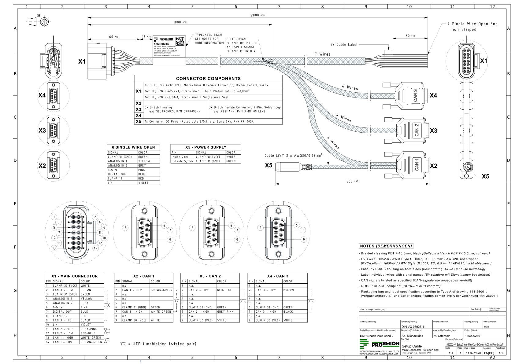
The following cable assembly drawing shows the connectors, pin assignment, and wire colors.
Figure 1: Setup Cable (136000246)
The cable is equipped with the following connectors and open wires:
Main Plug Connector (X1)
CAN 1 (X2)
CAN 2 (X3)
CAN 3 (X4)
Power Supply (X5)
Open Wires
Main Plug Connector
The pin designation and description match the device's main plug connector, see Connectors . The following table lists the wire color and cable end for each pin.
Pin
Color
Cable End
1
White
CAN 1, CAN 2, CAN 3
2
Brown
CAN 3
3
Green
CAN 1, CAN 2, CAN 3, Open Wire
4
Yellow
Open Wire
5
Grey
Open Wire
6
Pink
Open Wire
7
Blue
Open Wire
8
Red
Open Wire
9
Black
CAN 3
10
Violet
Open Wire
11
Grey-Pink
CAN 2
12
Red-Blue
CAN 2
13
White-Green
CAN 1
14
Brown-Green
CAN 1
CAN 1
Pin
Designation
Color
Description
1
n.a.
-
-
2
CAN1-Low
Brown-Green
CAN, bidirectional
3
n.a.
-
-
4
n.a.
-
-
5
n.a.
-
-
6
Terminal 31 (GND)
Green
Power supply
7
CAN1-High
White-Green
CAN, bidirectional
8
n.a.
-
-
9
Terminal 30 (VCC)
White
Power supply
CAN 2
Pin
Designation
Color
Description
1
n.a.
-
-
2
CAN2-Low
Red-Blue
CAN, bidirectional
3
n.a.
-
-
4
n.a.
-
-
5
n.a.
-
-
6
Terminal 31 (GND)
Green
Power supply
7
CAN2-High
Grey-Pink
CAN, bidirectional
8
n.a.
-
-
9
Terminal 30 (VCC)
White
Power supply
CAN 3
Pin
Designation
Color
Description
1
n.a.
-
-
2
CAN3-Low
Brown
CAN, bidirectional
3
n.a.
-
-
4
n.a.
-
-
5
n.a.
-
-
6
Terminal 31 (GND)
Green
Power supply
7
CAN3-High
Black
CAN, bidirectional
8
n.a.
-
-
9
Terminal 30 (VCC)
White
Power supply
Power Supply
Pin
Designation
Color
Description
Inside (2 mm)
Terminal 30 (VCC)
White
Power supply
Outside (5.7 mm)
Terminal 31 (GND)
Green
Power supply
Open Wires
Pin
Designation
Color
Description
4
Analog input 1
Yellow
I/O input
5
Analog input 2
Grey
I/O input
6
1-Wire
Pink
External 1-Wire devices
7
Digital output
Blue
I/O output
8
Terminal 15
Red
Input (ignition signal)
10
LIN
Violet
External LIN devices