Connectors
Depending on the housing form, CANlink® mobile 3700 is equipped with up to three connectors:
- Main Plug Connector (Micro Timer II, 14-pin)
- External Antenna Connector (Quad HFM, Z-code)
- Ethernet Connector (H-MTD, Z-code)
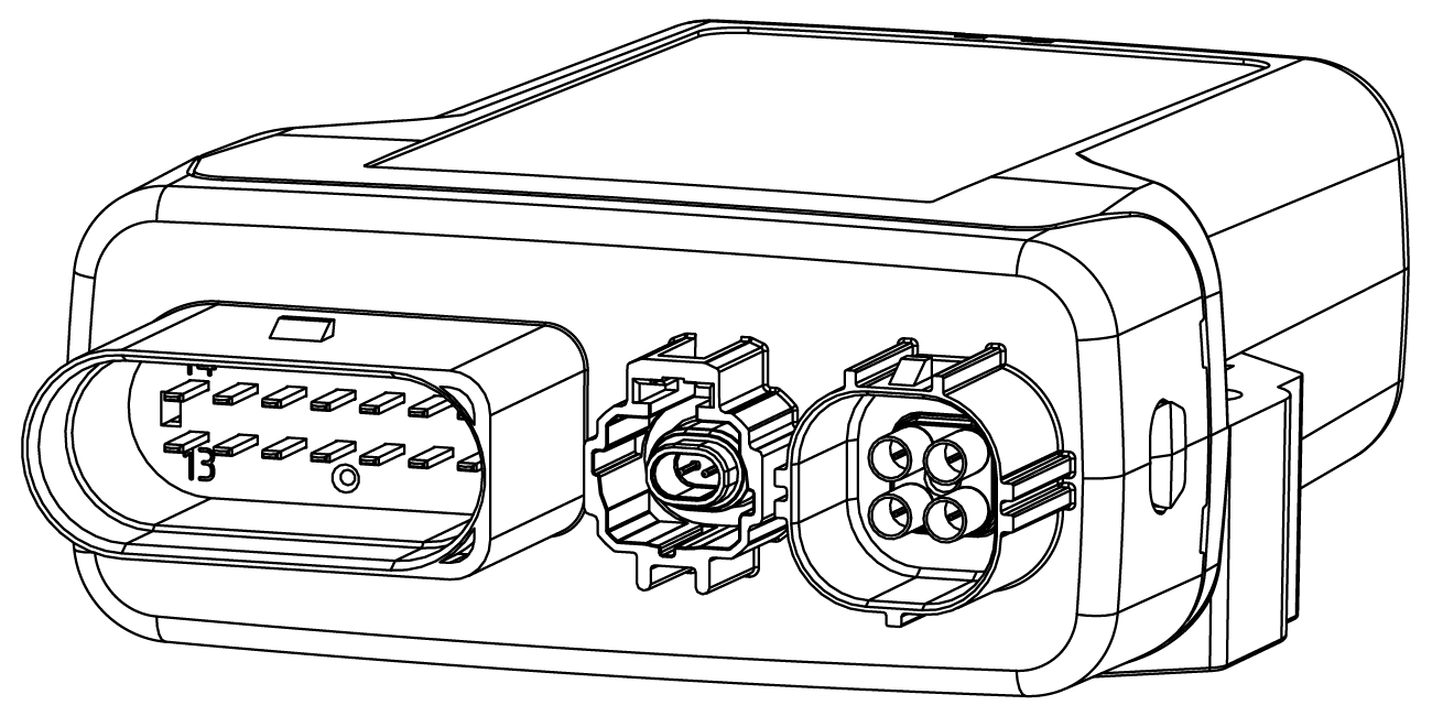
Not every housing form has all three connectors, see Available Models and Types to determine which connectors are present on a given device type.
Warning
Do not use any tools to force a connection. Damage to the contact carrier or the pins can impair the function.
Main Plug Connector
Use the main plug connector to connect the device to the CAN bus and supply it with power. The I/O signals are integrated in the main plug connector.
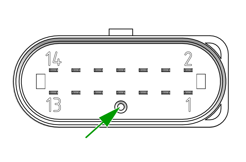
It contains a reset button, which is required to complete local firmware updates or to switch the device off in the case of types with an integrated, rechargeable battery.
Pin Assignment
See the following overview for the pin assignment:
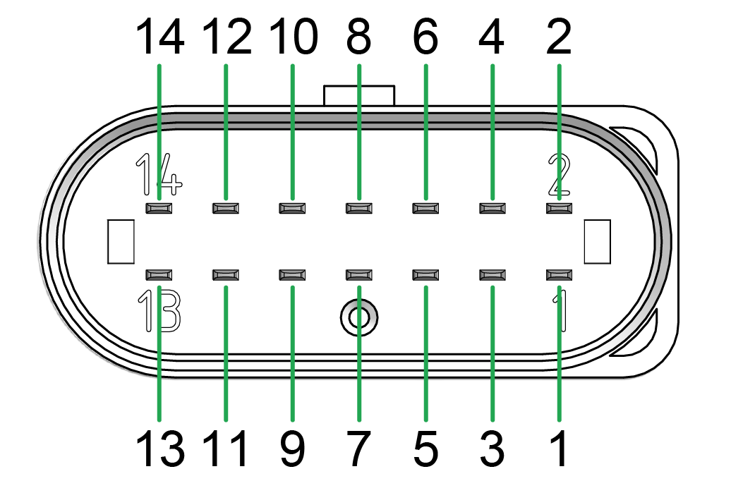
| Pin | Designation | Description |
|---|---|---|
| 1 | Terminal 30 / VCC | Power supply |
| 2 | CAN3-Low | CAN, bidirectional |
| 3 | Terminal 31 / ground | Power supply |
| 4 | Analog input 1 | I/O input |
| 5 | Analog input 2 | I/O input |
| 6 | 1-Wire | External 1-Wire devices |
| 7 | Digital output | I/O output |
| 8 | Terminal 15 | Input (ignition signal) |
| 9 | CAN3-High | CAN, bidirectional |
| 10 | LIN | External LIN devices |
| 11 | CAN2-High | CAN, bidirectional |
| 12 | CAN2-Low | CAN, bidirectional |
| 13 | CAN1-High | CAN, bidirectional |
| 14 | CAN1-Low | CAN, bidirectional |
For the electrical specifications of the analog inputs, digital output, and Terminal 15, see the Annex.
Note
Pin changes compared to CANlink® mobile 3600
The main plug connector keeps the same connector type (Micro Timer II, 14-pin) as on CANlink® mobile 3600, but two pin functions changed: pin 6 now carries 1-Wire instead of Analog input 3, and pin 10 now carries LIN instead of CAN2-GND.
CANlink® mobile 3700 supports 2 analog inputs instead of 3. If an application requires a third analog input, look for an alternative way to read that signal.
Leave pin 10 open if the application does not use LIN. If the application relies on a CAN2-GND connection on pin 10, provide the ground connection from another source in the cable harness.
Connection
To connect the main plug connector:
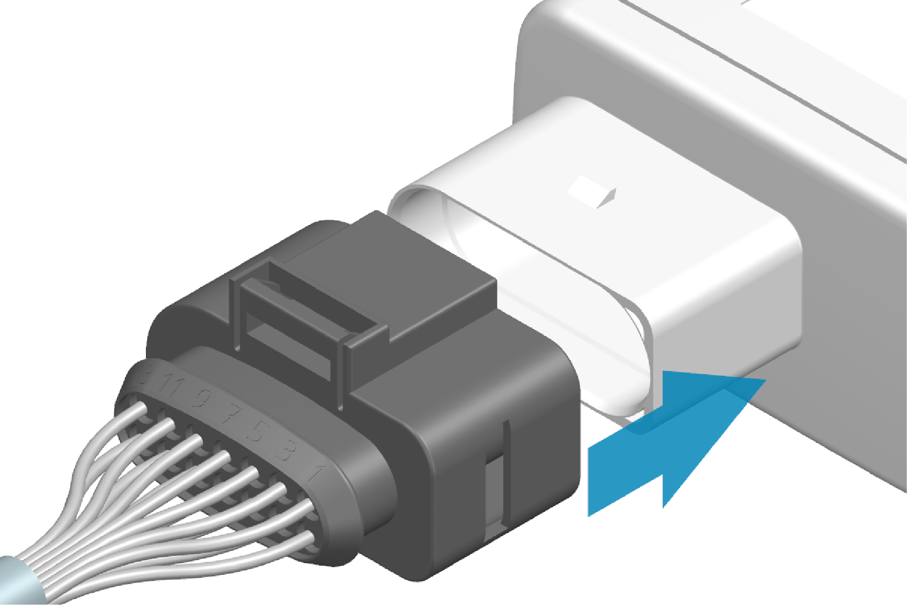
- Align the cable with the main plug connector.
- Insert it until you feel the locking mechanism engage; there must be a clear audible click when the lock is correctly engaged.
To disconnect the main plug connector:
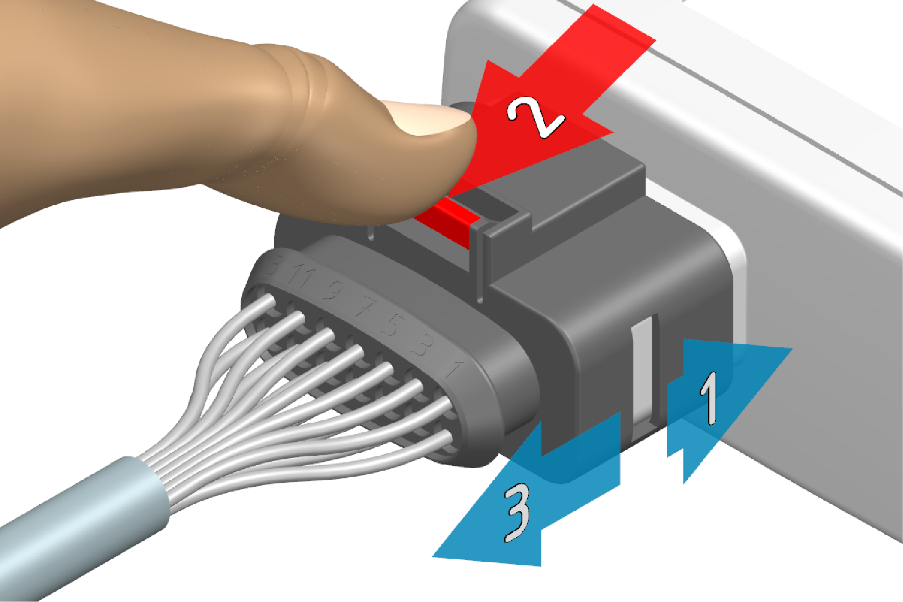
- Push in the plug so that the latch is released.
- Press and hold the release mechanism in the direction of the arrow to release the latch.
- Pull out the plug completely.
External Antenna Connector
Use the external antenna connector (Quad HFM, Z-code) to connect an external antenna for cellular, GNSS, and Wi-Fi®/BLE reception. On device types with an integrated antenna, this connector is not present.
Pin Assignment
See the following overview for the pin assignment:
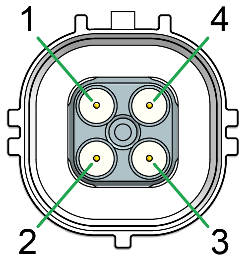
| Pin | Signal |
|---|---|
| 1 | Wi-Fi®/BLE |
| 2 | Cellular |
| 3 | GNSS |
| 4 | Not connected |
A compatible external antenna is available as an accessory, see Accessories.
Connection
To connect the external antenna connector:
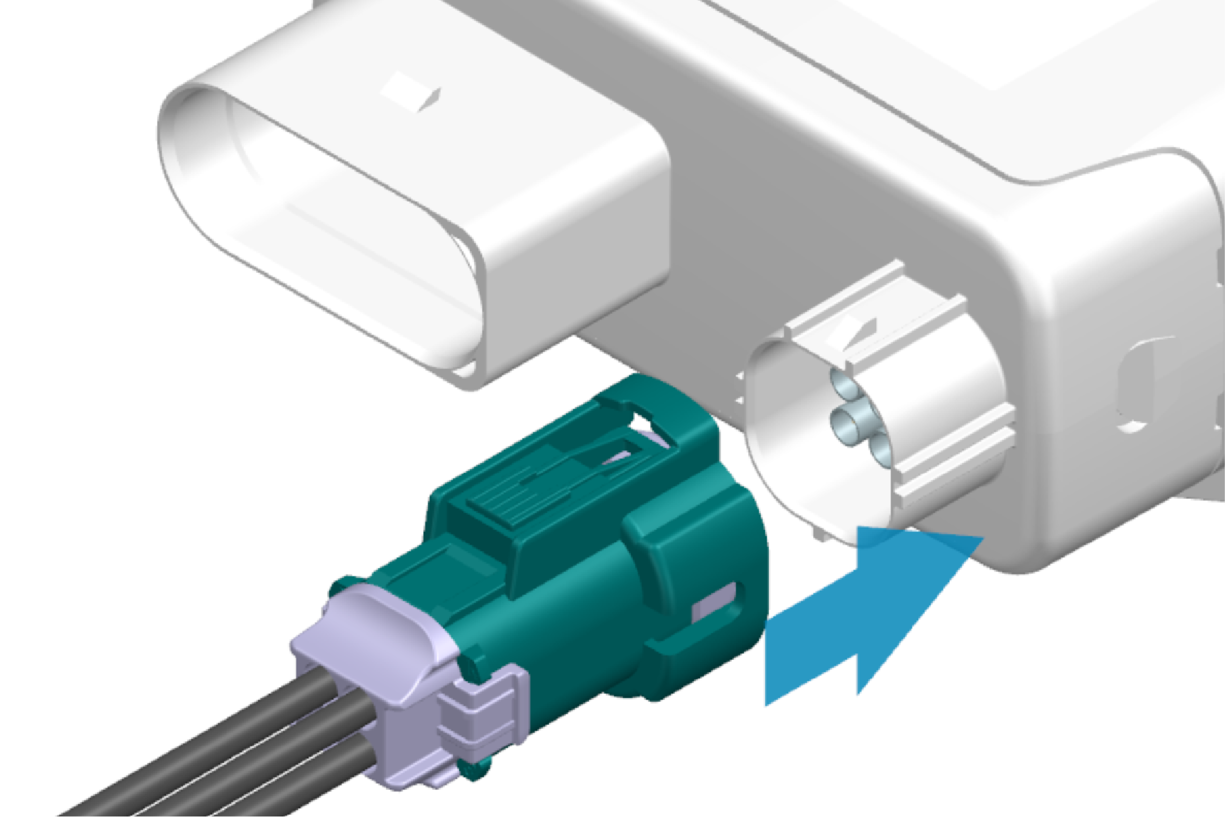
- Align the coding of the connector with the socket.
- Insert it until you feel the locking mechanism engage.
To disconnect the external antenna connector:
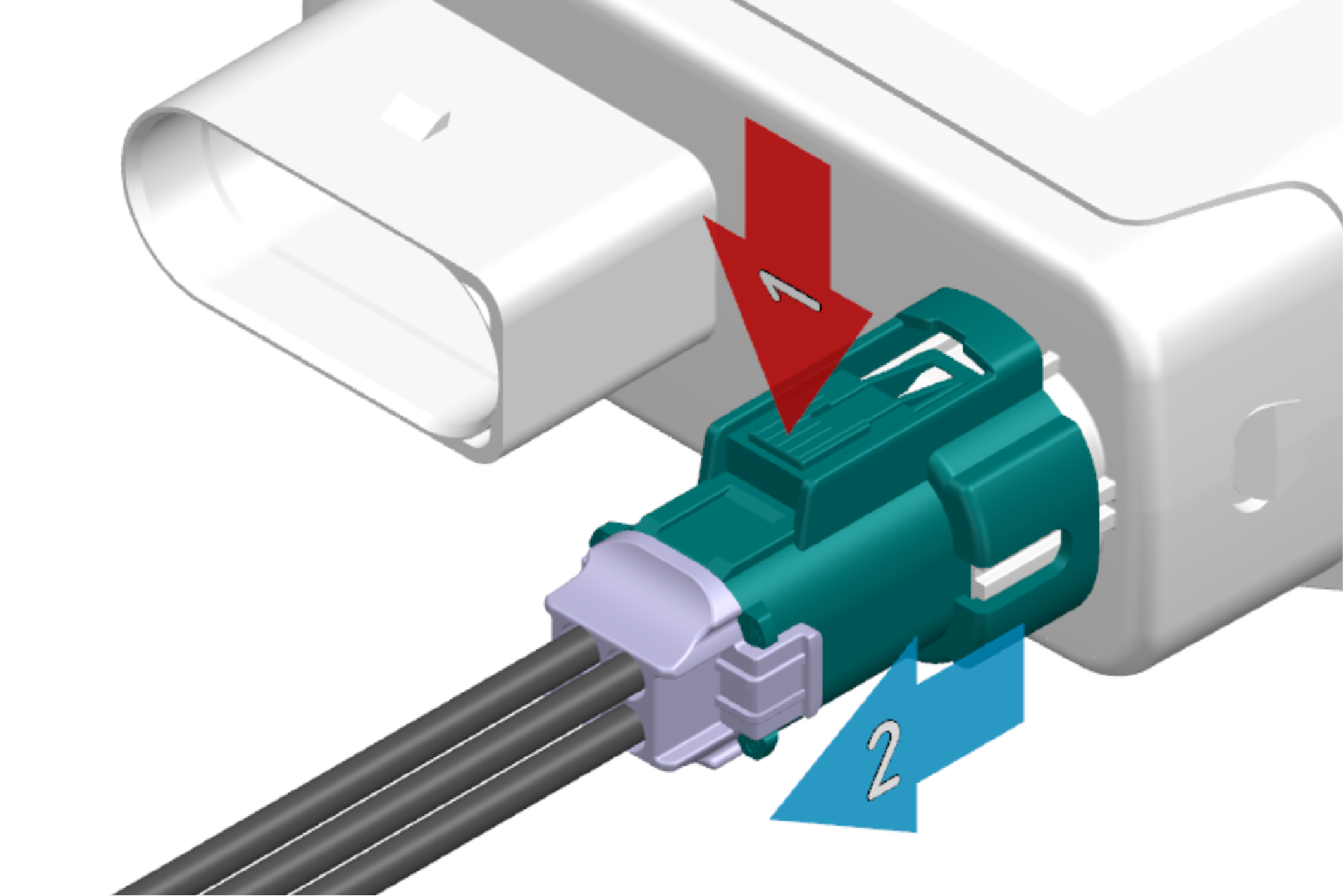
- Press and hold the release mechanism in the direction of the arrow to release the latch.
- Pull out the connector completely.
Ethernet Connector
Device types with an Ethernet connector (H-MTD, Z-code) provide a Single Pair Ethernet (SPE) interface. For the supported SPE standard and its firmware support status, see the Annex.
Connection
To connect the Ethernet connector:
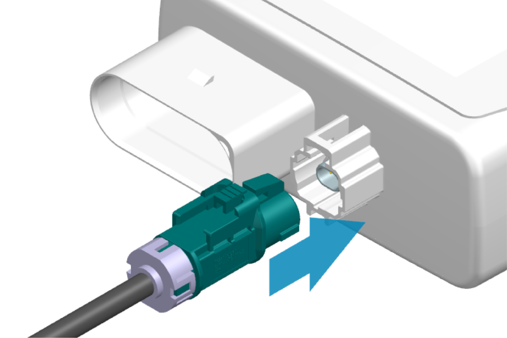
- Align the coding of the connector with the socket.
- Insert it until you feel the locking mechanism engage.
To disconnect the Ethernet connector:
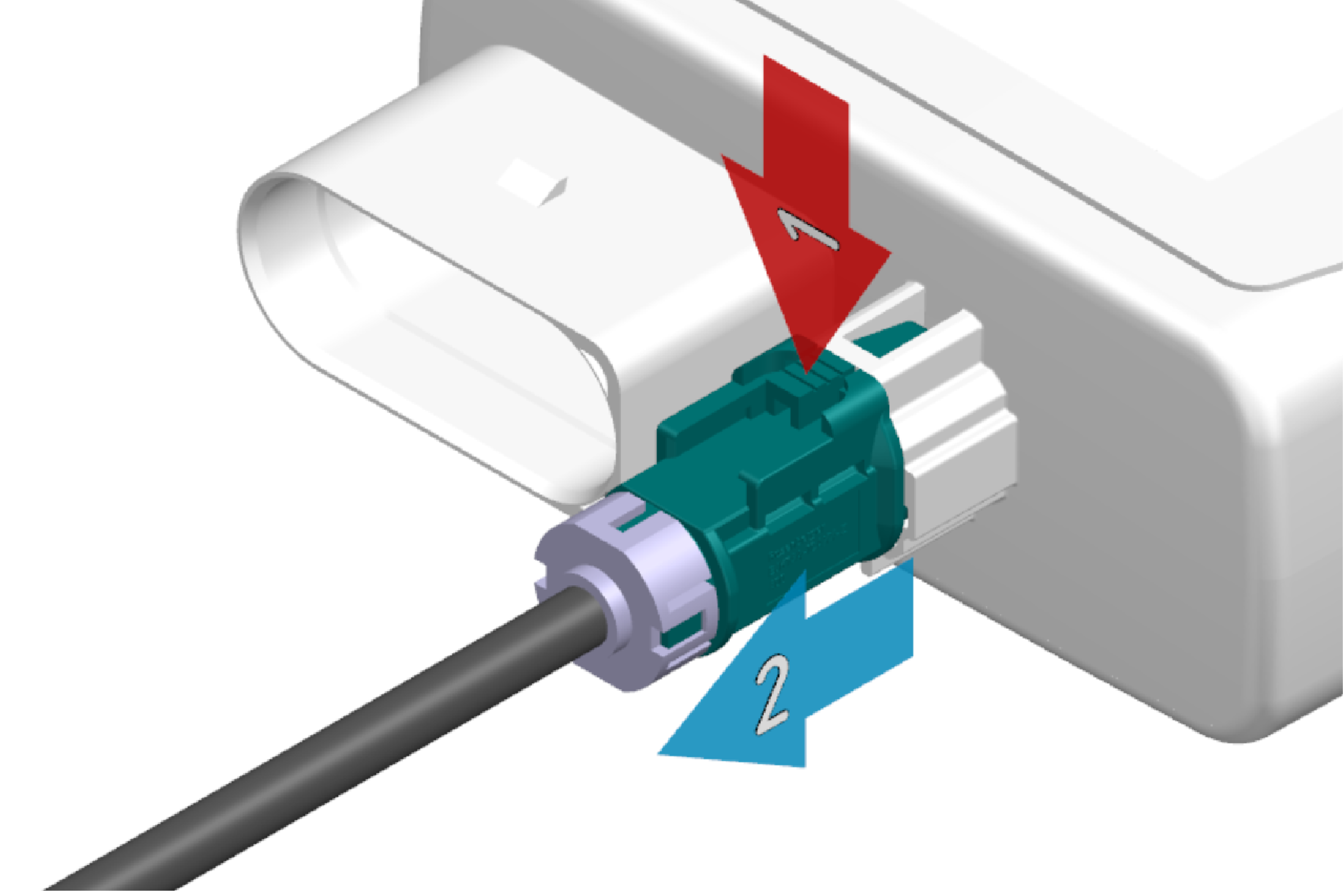
- Press and hold the release mechanism in the direction of the arrow to release the latch.
- Pull out the connector completely.