ECU FOTA BETA Documentation
ECU FOTA Overview
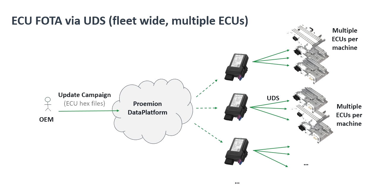
ECU Firmware Over-The-Air (ECU FOTA) enables OEMs to remotely update the firmware of Electronic Control Units (ECUs) installed in their machines without requiring physical access or on-site service visits.
By enabling remote firmware distribution, ECU FOTA allows OEMs to efficiently deploy bug fixes, security patches, and new features across entire fleets - without service-truck rolls, reducing maintenance effort and minimizing machine downtime. Starting December 2027, the EU Cyber Resilience Act (CRA) will additionally require OEMs to provide security updates throughout a product's lifetime, making remote update capability a regulatory necessity.
How it works at Proemion: Firmware updates are initiated through the DataPortal and delivered wirelessly to the target ECU via the Telematics Control Unit (TCU). The machine operator approves the update on-site before flashing begins, and OEM-side software confirms the result afterwards. Together, this gives OEMs a traceable, low-effort path to fleet-wide firmware updates while ensuring operators are never caught off guard by unplanned downtime.
ECU FOTA uses the Unified Diagnostic Services (UDS) protocol (ISO 14229) for ECU reprogramming - an industry standard that ensures out-of-the-box compatibility with existing ECU bootloaders and established firmware update workflows, without requiring proprietary flashing tools.
Note
ECU FOTA is currently in a BETA phase and available as part of an early access program. Functionality, interfaces, workflows, and integration behavior may change during the beta program. This documentation applies to CANlink® mobile 3600, firmware release 4.2 or later. Customers interested in ECU FOTA must contact their Account Manager or Field Application Engineer (FAE) at Proemion.
See Onboarding for details on how to participate and what to expect.
Terminology
The following terms are specific to ECU FOTA and are used throughout this documentation.
| Term | Definition |
|---|---|
| ECU | Electronic Control Unit. An embedded controller installed in a machine that manages specific functions such as hydraulics, drive, or engine control. ECU firmware can be updated remotely via ECU FOTA. |
| ECU FOTA | ECU Firmware Over-The-Air. The capability to remotely update ECU firmware without physical access to the machine, using the UDS protocol delivered via the Proemion TCU. |
| TCU | Telematics Control Unit. The Proemion CANlink® mobile that downloads firmware from the DataPlatform, manages CANopen communication, and performs UDS flashing of the target ECU. |
| UDS | Unified Diagnostic Services (ISO 14229). Industry-standard communication protocol used in automotive and industrial electronics for diagnostics, reprogramming, and testing of ECUs. Used by the TCU to flash new firmware to the ECU. |
| Electronic Architecture (EA) | A DataPlatform definition of the ECU topology for a specific machine type — which ECUs are present, how they are addressed on the CAN bus, and which firmware is compatible with each. |
| Software Repository | A version-managed collection of firmware files in the DataPlatform for one specific ECU type, identified by ECU Brand and Model. |
| ECU Update Request | An instruction created in the DataPlatform to deploy a specific firmware version to a specific ECU on a specific machine. |
| Bootloader Address | The CAN address the ECU uses during programming mode. Distinct from the application address used during normal operation. |
| Checkpoint 1 | Operator approval required before flashing begins. The machine operator explicitly approves or rejects the update via HMI or CANopen client. |
| Checkpoint 2 | Health verification required after flashing. OEM software confirms the new ECU application is running correctly. |
| OEM Logic | Customer-side software responsible for implementing Checkpoint 2 and reporting the verification result to the TCU. |
| ECU:Admin | DataPortal permission set required to access Software Repositories, Electronic Architectures, and ECU update requests. |
High-Level Workflow
The update process involves three parties: the DataPortal user who triggers the update, the machine-side operator who approves it, and the OEM software that confirms the result.
- Upload ECU firmware to a Software Repository
- Configure the Electronic Architecture and ECU mappings
- Trigger an ECU update in the DataPortal
- TCU downloads and verifies the firmware package
- Checkpoint 1: Machine operator approves the update via HMI
- TCU flashes the new firmware to the ECU
- ECU reboots and starts the new application
- Checkpoint 2: OEM software verifies ECU health and reports the result
- Update is finalized and the result is reported to DataPlatform
Note
In the event of a flashing failure, the ECU bootloader is always preserved, ensuring the ECU remains accessible for a subsequent remote update attempt.
The following diagram illustrates the high-level workflow.
flowchart TD
    classDef default fill:#f5f5f5,color:#1E2A3A,stroke:#ccc
    classDef checkpoint fill:#fff8e1,color:#1E2A3A,stroke:#f0a500

    subgraph DataPortal["DataPortal (Fleet Manager)"]
        A[Upload firmware] --> B[Configure architecture]
        B --> C[Trigger update]
    end
    subgraph Machine["On-machine (OEM integration)"]
        D[TCU downloads firmware]
        E[Checkpoint 1 — operator approves]
        F[UDS flashing via TCU]
        G[ECU reboots]
    end
    subgraph DataPlatform["DataPlatform"]
        H[Checkpoint 2 — health verified]
        I[Update successful]
    end

    C --> D
    D --> E
    E --> F
    F --> G
    G --> H
    H --> I

    style DataPortal fill:#dce8f5,color:#1E2A3A,stroke:#1E2A3A
    style Machine fill:#d6f0e2,color:#1E2A3A,stroke:#22A652
    style DataPlatform fill:#eae8f5,color:#1E2A3A,stroke:#2A3A50

    class E,H checkpoint
Documentation Overview
This manual covers the following topics:
- Onboarding — Beta program access, integration responsibilities, and prerequisites.
- Upload and Manage ECU Firmware — Creating Software Repositories and uploading HEX files.
- Configure Electronic Architecture — Defining ECU topology, CAN addressing, and machine assignments.
- Trigger ECU Update — Triggering and monitoring firmware deployments from the DataPortal.
- HMI Approval Interface — Machine-side operator approval and OEM health verification workflow.
- CANopen Specification — Full CANopen object dictionary, state machine, and integration reference.
Onboarding
ECU FOTA beta access is not available through self-service sign-up.
To participate, contact your Account Manager or Field Application Engineer (FAE) at Proemion. Proemion will enable ECU FOTA on your organization and configure the required TCUs.
Warning
ECU FOTA is currently in BETA phase. Functionality, interfaces, and integration behavior may change during the program.
What to Expect During Integration
Beta integrations require close coordination with Proemion. This is not a hands-off deployment.
Based on experience with beta customers:
- An onboarding call is held before integration begins.
- A troubleshooting session after the first integration attempts is consistently needed to resolve outstanding issues. Plan for this proactively.
- Iterative testing of both HMI checkpoints, status polling, and health check logic is required before deploying to production machines.
Note
Based on experience from previous beta customers, a dedicated troubleshooting session after first integration attempts should be scheduled as a standard step — not treated as an exception.
Prerequisites and Responsibilities
Before beginning the technical setup, verify the following requirements are fulfilled.
| Requirement | Description | Owner |
|---|---|---|
| ECU FOTA activated | ECU FOTA enabled on your organization and ECU FOTA toggle activated on target TCUs | Proemion |
| TCU power-cycled | Target TCUs power-cycled after ECU FOTA toggle activation — required for the toggle to take effect | OEM / Customer |
| TCU firmware version | Target TCUs running firmware 4.2 or later - see Firmware update | OEM / Customer |
| User permissions | User account has ECU:Admin Permission Set and Lab Mode enabled. | OEM / Customer |
| DataPortal setup | Software Repositories, Electronic Architecture, and ECU Update Requests configured | OEM / Customer |
| HMI / CANopen integration | Checkpoint 1 (operator approval) and Checkpoint 2 (health verification) implemented | OEM / Customer |
| ECU information available | ECU CAN addresses (bootloader), CAN interface, and authentication credentials — provided by the ECU manufacturer | OEM / Customer |
| Firmware file available | Valid Intel HEX file for the target ECU — provided by the ECU manufacturer | OEM / Customer |
| Troubleshooting sessions | Alignment sessions during integration | Proemion + OEM / Customer |
Note
For SSO users, the ECU:Admin permission set must be included in the relevant role in your Identity Provider (IdP) - see SSO Login for details. After the role is updated in the IdP, the user must log out of the DataPortal and log back in — re-logging into the IdP alone is not sufficient.
DataPortal Setup
Upload and Manage ECU Firmware
The first step in setting up ECU FOTA in the DataPortal is to upload the target firmware to a Software Repository — a version-managed store that holds all available firmware versions for a specific ECU type. Once the firmware is uploaded, it can be selected when creating an ECU update request.
To deploy it to a machine, you also need to configure the Electronic Architecture.
Before starting, ensure you have a valid Intel HEX file for the target ECU — provided by the ECU manufacturer.
Create a Software Repository
-
Navigate to Settings > ECU Management > Software Repositories.
-
Click Create repository in the top right corner.
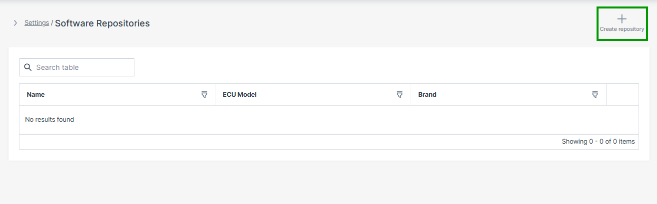
Figure 1: Software Repositories Overview -
Configure the repository parameters:
Parameter Description Name A descriptive name for this repository Description Optional description ECU Brand The ECU manufacturer, selected from dropdown ECU Model The specific ECU model identifier, selected from dropdown The ECU Brand and ECU Model configured here are later matched against the Electronic Architecture to ensure firmware is deployed only to compatible controllers.
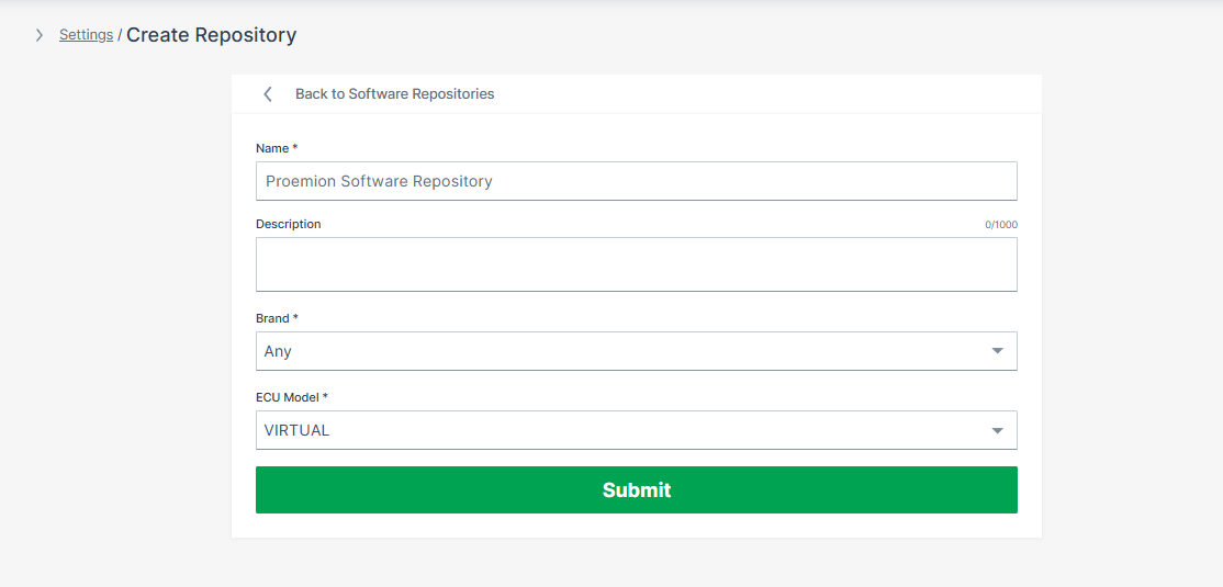
Figure 2: Create Software Repository -
Click the Submit button.
The Software Repository is now successfully created.
Add a Firmware Version
-
Click Add software version in the top right corner of the repository detail page.
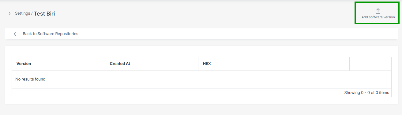
Figure 3: Add Software Version -
Enter the following and click Create:
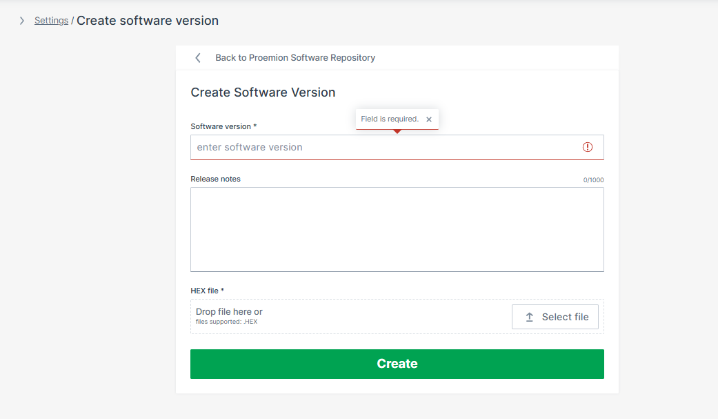
Figure 4: Add Firmware Version
| Field | Description |
|---|---|
| Software version | Firmware version identifier, e.g. 1.4.2 |
| Release notes | Optional description of changes in this version |
| HEX file | ECU firmware image — drag and drop or click Select file. Supported format: .HEX |
The firmware version is now available for ECU update requests.
Troubleshooting
| Problem | Possible Cause |
|---|---|
| Upload button unavailable | Missing ECU:Admin permission set — see Onboarding |
| Repository menu not visible | Lab Mode not enabled — see Onboarding |
| Upload rejected | Invalid or unsupported firmware file format — only .HEX is supported |
| Firmware not deployable | ECU mapping not yet configured in the Electronic Architecture |
| ECU update unavailable | ECU FOTA not enabled on the target TCU |
Next Steps
Configure the Electronic Architecture
An Electronic Architecture (EA) tells the system which ECUs are installed on a specific machine type, how to reach them on the CAN bus, and which firmware is compatible with each — so the right firmware is always deployed to the right controller. It serves as a reference architecture for a machine platform: all machines of the same type share the same Electronic Architecture.
Once configured, the EA is assigned to individual machines so the system knows which ECUs can be updated and how to reach them.
flowchart TD
    EA["Electronic Architecture<br/>e.g. Excavator-X200"]
    ECU1["ECU Definition<br/>e.g. Hydraulics Controller<br/>Brand: TTControl / Model: TTC 2390"]
    ECU2["ECU Definition<br/>e.g. Drive Controller<br/>Brand: Bosch Rexroth / Model: BODAS RC5-6/40"]
    REPO1["Software Repository<br/>Brand: TTControl / Model: TTC 2390"]
    REPO2["Software Repository<br/>Brand: Bosch Rexroth / Model: BODAS RC5-6/40"]
    M1["Machine<br/>Unit #1001"]
    M2["Machine<br/>Unit #1002"]
    EA --> ECU1
    EA --> ECU2
    ECU1 -.->|"Brand/Model match"| REPO1
    ECU2 -.->|"Brand/Model match"| REPO2
    EA --> M1
    EA --> M2
The Electronic Architecture must be configured before ECU update requests can be executed.
Step 1 - Create the Electronic Architecture
-
Navigate to Settings > ECU Management > Electronic Architectures.
-
Click Create Architecture in the top right corner.
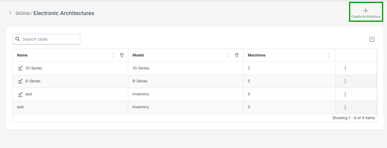
Figure 1: Electronic Architectures Overview -
Enter the following and click Create:
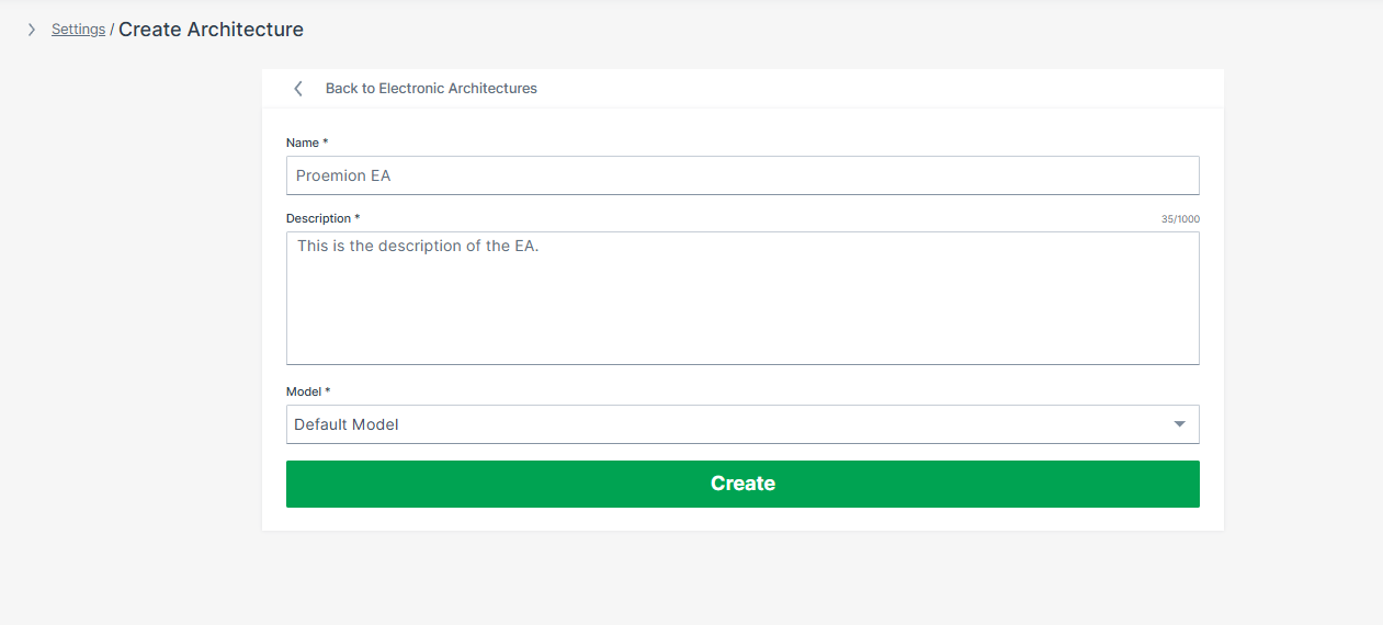
Figure 2: Create Architecture
| Field | Description |
|---|---|
| Name | A descriptive name for this machine type, e.g. Excavator-X200 |
| Description | A description of this architecture |
| Model | The machine model this EA applies to, selected from a dropdown list |
The Electronic Architecture is now successfully created.
Step 2 - Add an ECU Definition
Each ECU to be updated via ECU FOTA must be added to the Electronic Architecture individually. The ECU definition is configured in four-steps: ECU info > Connection info > Bootloader configuration > Authentication.
-
In the newly created EA, click Create ECU in the top right corner.
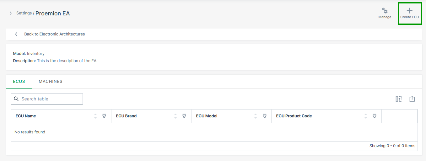
Figure 3: Create ECU -
Enter the ECU info and click Continue:
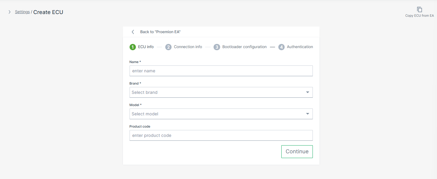
Figure 4: ECU Info Field Description Name A descriptive name for this ECU, e.g. Hydraulics ControllerBrand ECU manufacturer, selected from dropdown list — must match the Brand of the Software Repository Model ECU model identifier, selected from dropdown list — must match the Model of the Software Repository Product Code Optional reference to your ERP system -
Enter the Connection info and click Continue:
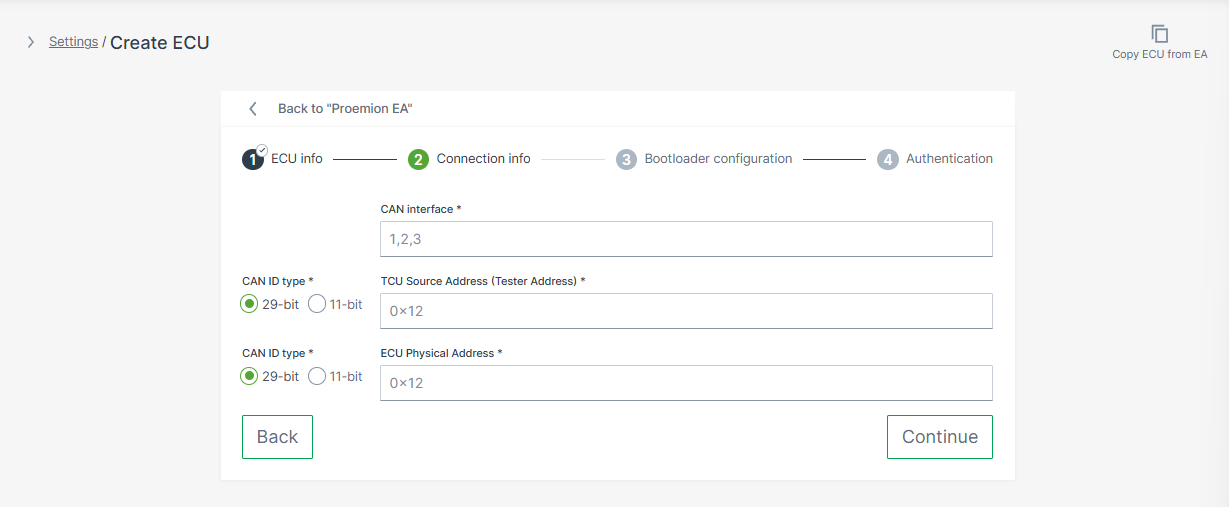
Figure 5: Connection Info Warning
Enter the ECU's bootloader addresses here — not its normal operating (application) addresses. The bootloader address is the address the ECU uses during programming mode, which is different from the address used during normal operation. Using the wrong address type will prevent flashing from starting. The correct bootloader address is provided by the ECU manufacturer.
Field Description CAN Interface The physical CAN port on the TCU this ECU is connected to: 1,2, or3. Must match the actual machine wiring.CAN ID Type 11-bitor29-bit— set independently for TCU Source Address and ECU Physical AddressTCU Source Address The CAN ID the TCU uses to send diagnostic requests (tester address). Default: 0x7E0(11-bit)ECU Physical Address The CAN ID of the ECU in bootloader mode. Default values: TTC controllers: 0x7E7or0x7EF(11-bit); Bosch Rexroth controllers:0x18DA01FAor0x18DAFA01(29-bit) -
Optionally, enter the Bootloader configuration:
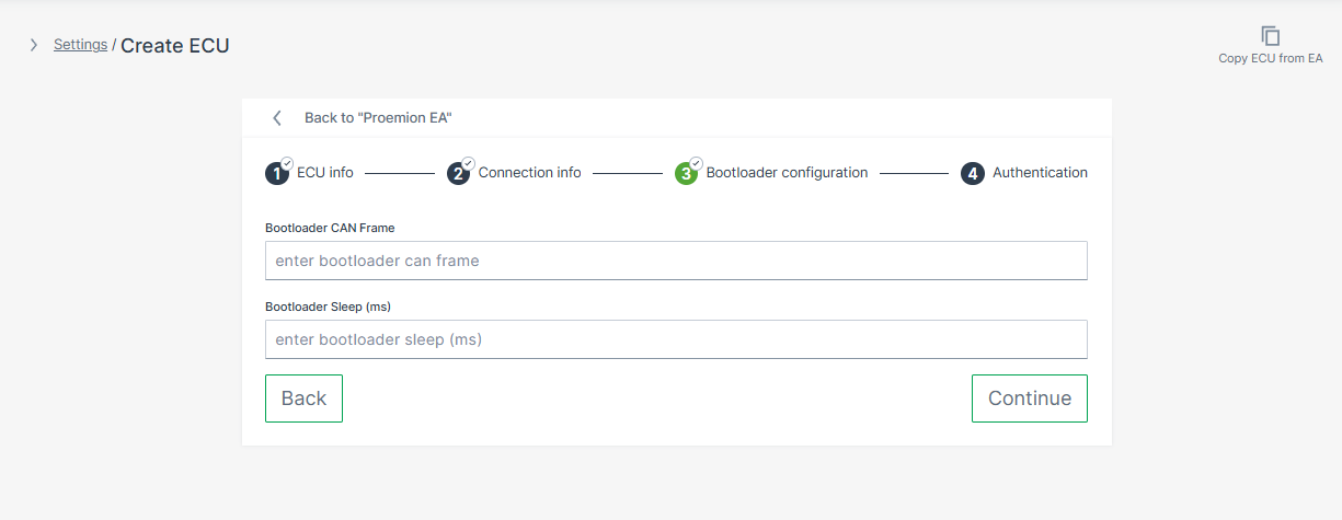
Figure 6: Bootloader Configuration Some ECUs require a specific CAN message to switch into programming mode before flashing can begin. If your ECU requires this, configure the Bootloader CAN Frame and Bootloader Sleep fields.
Whether your ECU requires a bootloader trigger depends on the ECU type:
- Bosch Rexroth controllers — no external trigger is required. The bootloader switch is handled within the standard UDS programming sequence.
- TTC controllers — the OEM defines the trigger via the TTC SDK. The CAN frame is not specified by TTC; it can be any application-defined CAN message.
When configured, the TCU sends the bootloader CAN frame, waits the specified delay, and then starts the UDS programming session. If no trigger is required, leave both fields empty.
Warning
The bootloader trigger must only be active after
update_available = 0x01and the operator has writtenapply_update = 0x01. Any earlier attempts to switch the ECU into bootloader mode must be ignored by the ECU. This applies to both TTC and Bosch Rexroth controllers.Field Description Bootloader CAN Frame CAN frame sent to switch the ECU into bootloader mode before flashing. Uses cansendformat:CANID#DATAwhere the CAN ID is in hexadecimal and DATA is a sequence of hex bytes, e.g.01111111#0100000000000000. Provided by the ECU manufacturer.Bootloader Sleep (ms) Delay in milliseconds the TCU waits after sending the bootloader frame before initiating the UDS programming session, e.g. 500. -
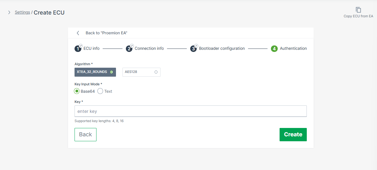
Enter the Authentication credentials and click Create:
| Field | Options |
|---|---|
| Algorithm | XTEA_32_ROUNDS or AES128 — supported algorithms depend on the ECU model |
| Key Input Mode | Base64 or Text — use Base64 for keys containing non-printable bytes |
| Key | Authentication key — supported lengths: 4, 8, or 16 bytes. The key is treated as a password and cannot be retrieved via the UI or API after saving. |
The ECU definition is now part of the Electronic Architecture.
Repeat Step 2 for each additional ECU in this architecture.
Step 3 - Assign Machines
After all ECU definitions are configured, assign the target machines to the EA. This tells the system which physical machines use this ECU topology.
-
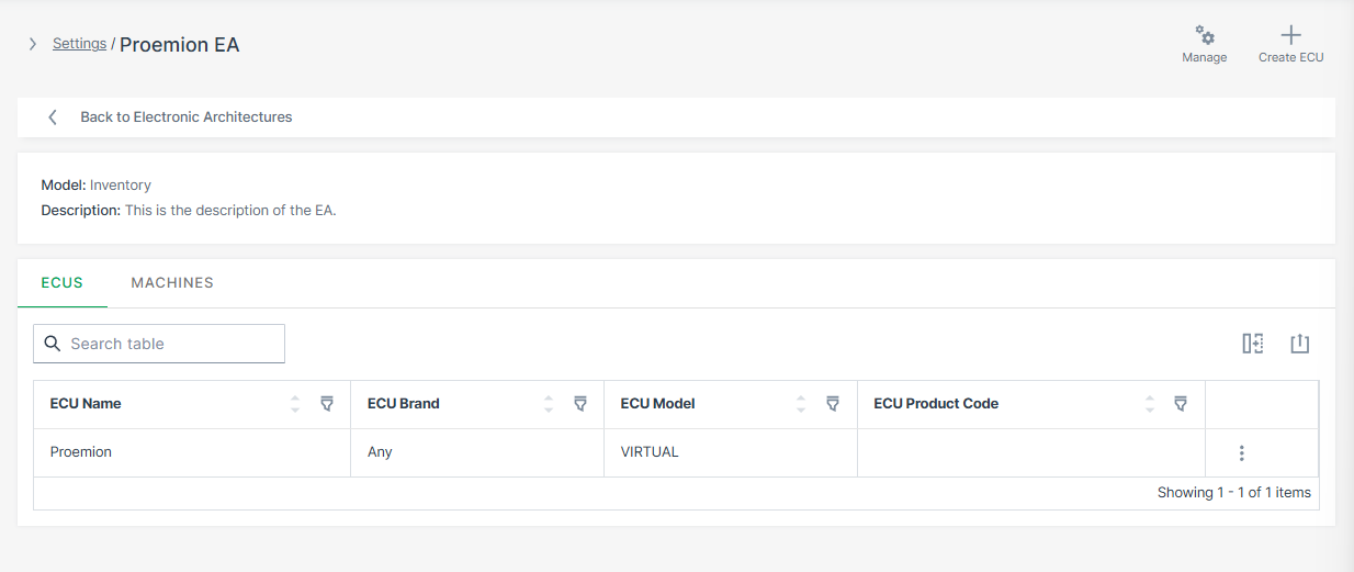
Select the EA you want to assign to a machine from the EA page.
-
Select the Machines tab and click Manage Machines.
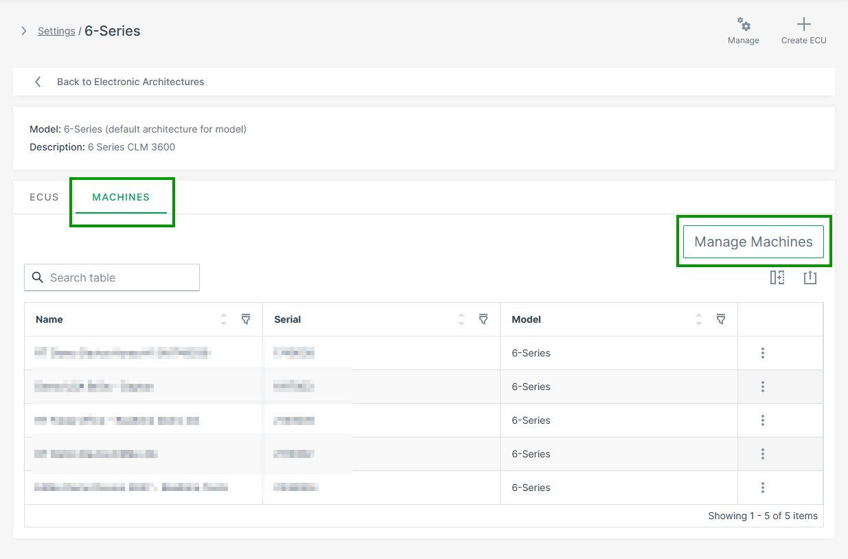
Figure 8: Assign Machine to EA -
Select the target machines and click Save.
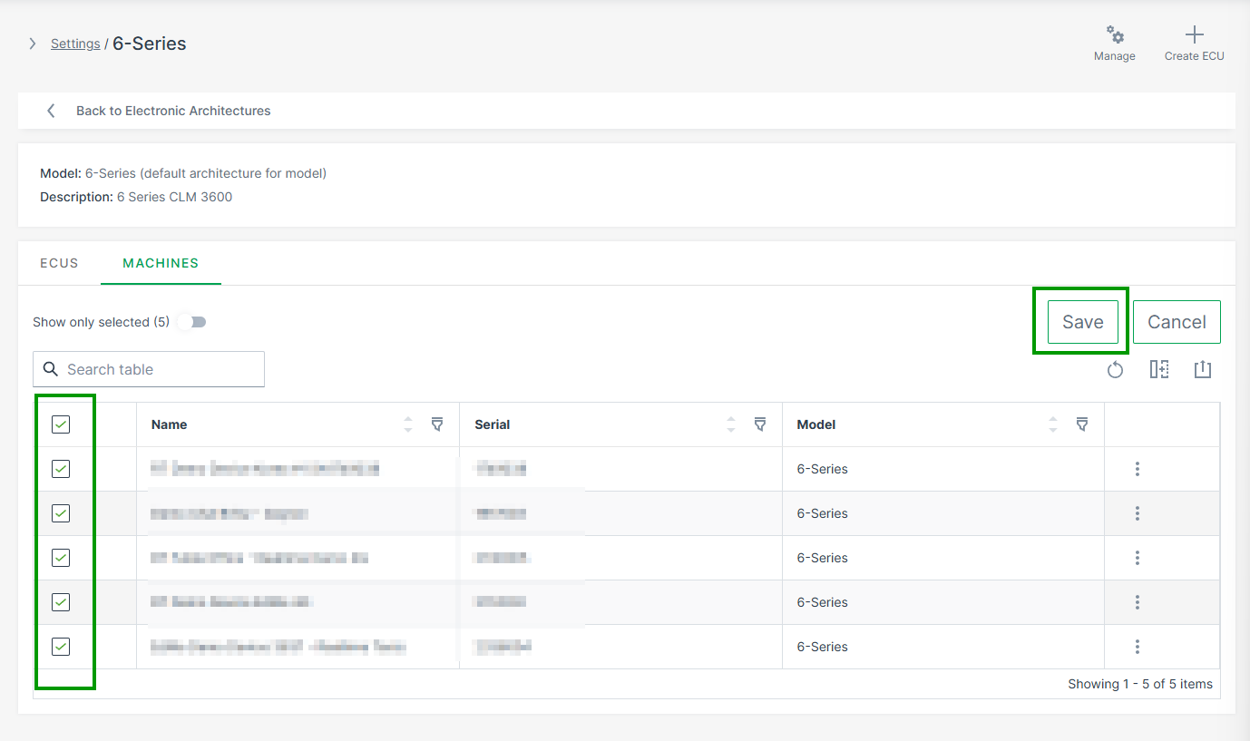
Figure 9: Select Machines
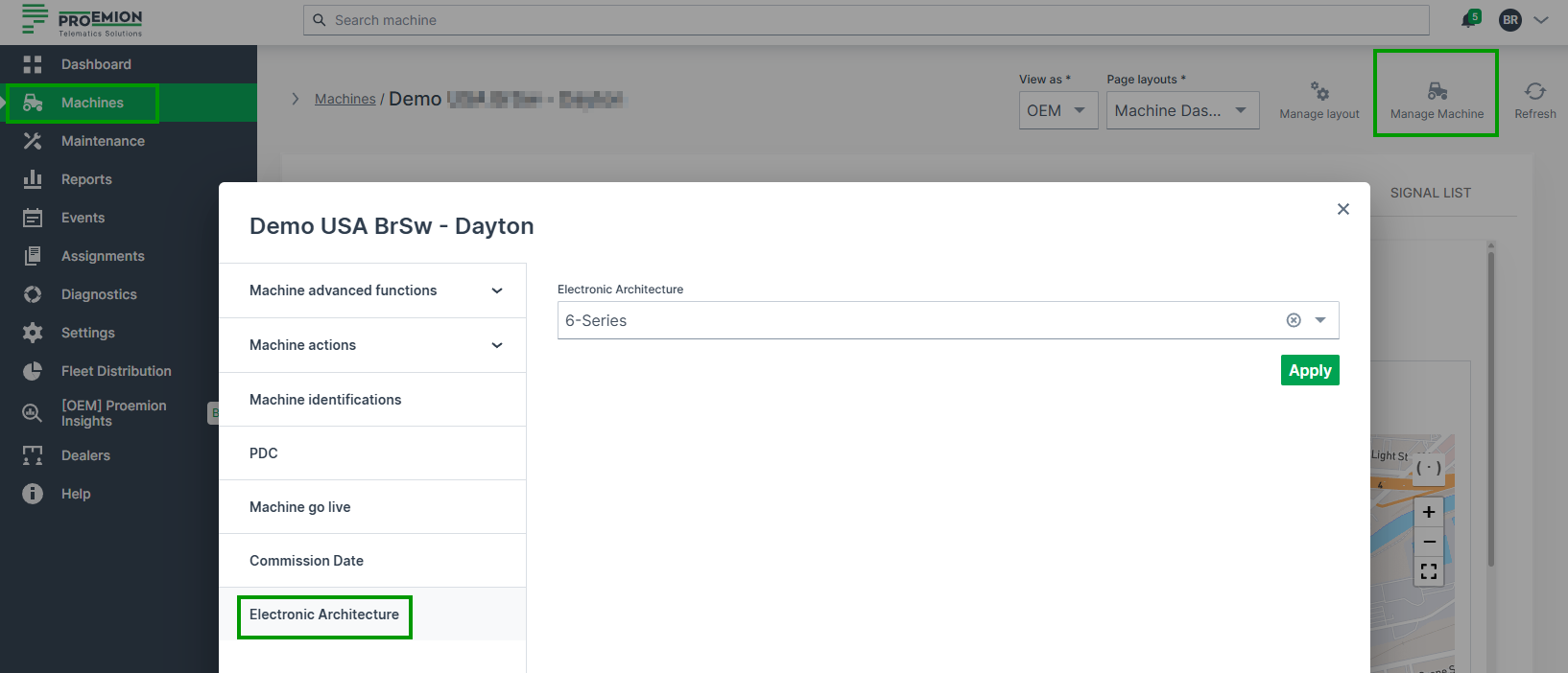
Alternatively, you can also assign machines to the EA via the Manage Machine Dialog.
Go to Machine Page > Manage Machine > Electronic Architecture.
Validation
Before creating ECU update requests, verify the configuration is complete:
| Check | How to verify |
|---|---|
| ECU visible in architecture | ECU appears in the architecture's ECU list |
| Repository assigned and matching | Repository is shown next to the ECU with no mismatch warning |
| CAN IDs configured | Request and Response CAN IDs are filled in |
| Machine assigned to EA | Machine appears in the architecture's machine list |
| ECU FOTA enabled on TCU | Confirmed by Proemion during onboarding |
Troubleshooting
| Problem | Possible Cause |
|---|---|
| ECU missing in machine | Electronic Architecture not assigned to machine |
| Repository mismatch warning | ECU Brand or Model does not match the Software Repository |
| Machine not visible | Machine not yet assigned to the Electronic Architecture |
Next Steps
ECU Update Request
An ECU update request is the instruction to deploy a specific firmware version to a specific ECU on a specific machine. Once submitted, the request is delivered to the TCU, which handles the update process on the machine.
Note
Each update request targets one ECU on one machine. To update multiple ECUs, create a separate update request for each.
Trigger an Update Request
-
Navigate to Settings > ECU Management > Software Repositories.
-
Select a repository and open the Details page.
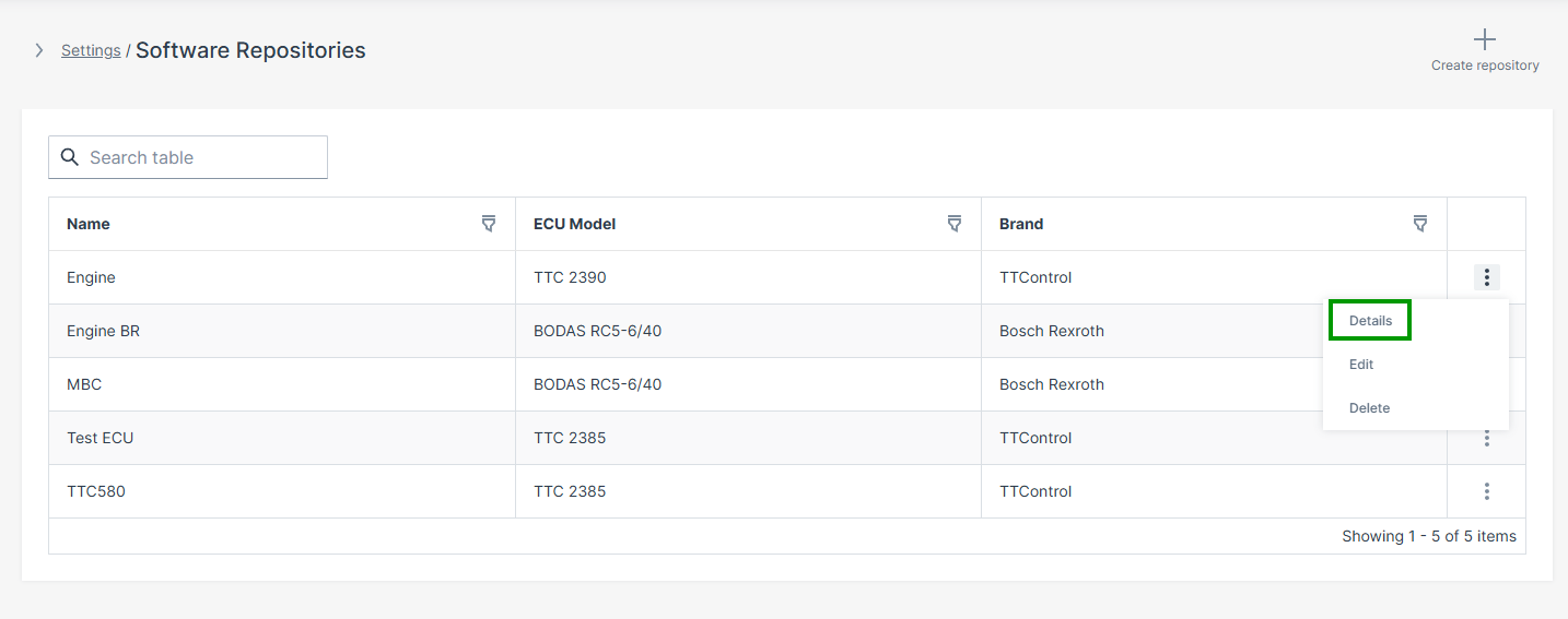
Figure 1: Software Repository Details -
Select Update to this version to submit the update request.
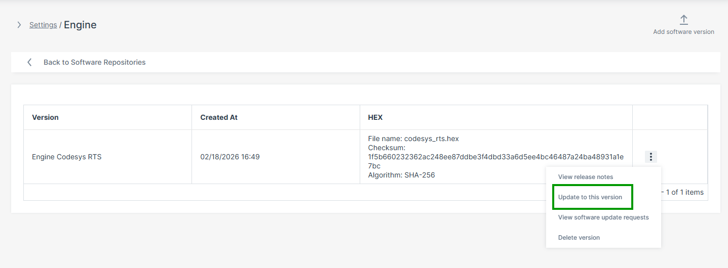
Figure 2: Update Request Option
The update page refreshes automatically.
Note
If the TCU is offline when the request is submitted, the update is queued and delivered automatically when the TCU reconnects. Multiple update requests for the same ECU are processed in the order they were created. The UI will warn you if there are pending updates when you create a new one.
After submission, the TCU downloads the firmware and signals to the machine that an update is available. The machine-side operator must then approve the update before flashing begins — see HMI Approval Interface for the full machine-side workflow.
Update Request Status
After submission, the update request detail page shows the current status. The following status values may appear:
| Status | Meaning |
|---|---|
| Pending | Update request created, waiting for TCU to come online |
| In progress | TCU has downloaded the firmware, awaiting operator approval or flashing |
| Successful | Update completed and verified |
| Failed | Flashing or health verification failed — check TCU log in the DataPortal |
| Cancelled | Update was cancelled before operator approval |
Cancel an Update Request
An update can be cancelled from the DataPortal as long as the machine-side operator has not yet approved it. Once the operator approves the update at Checkpoint 1, remote cancellation is no longer possible.
-
Navigate to Settings > ECU Management > Software Update Requests.
-
Open the relevant request.
-
Select Cancel update in the upper right corner.
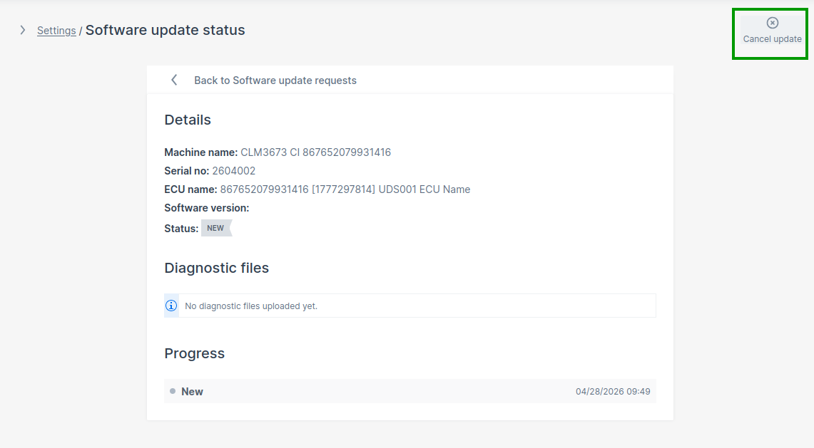
Figure 3: Cancel Update Request
If the TCU is offline, the cancellation is queued and delivered when the TCU reconnects.
Troubleshooting
| Problem | Possible Cause | Update Request Status |
|---|---|---|
| Machine not selectable | No Electronic Architecture assigned to the machine | — |
| ECU missing | ECU mapping incomplete in the Electronic Architecture | — |
| Firmware version unavailable | Repository mismatch — ECU Brand or Model does not match | — |
| Update request not executed | TCU offline — request is queued and will execute on reconnect | Status: Pending |
| Update remains pending | Machine-side operator has not yet approved the update (Checkpoint 1) | Status: In progress |
| Flashing does not start | Bootloader address incorrect — application address used instead of bootloader address | Status: Failed |
| ECU not reachable | Incorrect CAN addressing or wrong CAN interface | Status: Failed |
| Communication timeout | Wrong CAN interface selected | Status: Failed |
| Flashing fails | ECU bootloader transition failed or CAN communication problem | Status: Failed |
Next Steps
Machine-Side Integration
HMI Approval Interface
This document is an integration guide for the machine-side ECU FOTA workflow. It describes what needs to be implemented at each checkpoint — from signaling update availability to the operator, through to confirming that the new ECU firmware is working correctly. For the underlying CANopen object definitions, addresses, state machine details, and the state machine diagram, refer to the CANopen Specification.
This document is intended for the engineering team responsible for the machine's on-board software - typically the team developing the HMI display logic and ECU application validation.
Note
The OEM is responsible for ensuring the ECU is in a state that accepts a UDS programming session before approving the update. This includes verifying that no active processes on the machine interfere with CAN communication during flashing. Consult the ECU manufacturer's documentation for the specific preconditions required by your ECU model.
Terminology
Throughout this document, the following terms are used:
| Term | Meaning |
|---|---|
| HMI | The operator-facing display or control panel on the machine |
| CANopen client | Any software component that reads or writes the ECU FOTA CANopen objects |
| OEM logic | The OEM-side software responsible for Checkpoint 2 — verifying ECU health after flashing |
Checkpoint 1 is an operator decision, typically surfaced through the HMI. Checkpoint 2 is an automated software check, typically performed by OEM logic without operator involvement. Both checkpoints use the same CANopen interface.
The approval workflow can be implemented in HMI systems, PLCs, embedded OEM software, CANopen gateways, or custom logic running in the Proemion Configurator. The implementation approach is customer-specific.
Workflow Overview
The machine-side workflow consists of two mandatory checkpoints. The TCU waits for confirmation at each checkpoint before proceeding. The update is only finalized on DataPlatform after both checkpoints are completed.
| Checkpoint | When it occurs | What is required |
|---|---|---|
| Checkpoint 1 | After the TCU has downloaded and verified the firmware | Operator explicitly approves or rejects the update |
| Checkpoint 2 | After UDS flashing is complete and the ECU has rebooted | OEM logic confirms the ECU application is healthy |
Machine Preconditions
Before approving an ECU update at Checkpoint 1, verify:
- the machine is in a safe state for a firmware update
- ECU communication is stable
- power supply conditions are valid
- the operator has explicitly confirmed the update
Checkpoint 1 — Operator Approval
After the TCU has downloaded and verified the firmware image, it signals update availability by setting update_available to 0x01.
The machine-side client must:
- Detect that an update is available by reading
update_available(0x5FF3:0x01). - Display the pending update to the operator and request approval.
- Put the machine into a safe state before proceeding.
- Write the operator's decision to
apply_update(0x5FF3:0x40): 0x01— operator approved, trigger the update0x02— operator rejected, cancel the update
Warning
Before writing 0x01 to apply_update, ensure the target ECU is ready to accept a programming session.
If the ECU is busy or in an incompatible operating state, the TCU will be unable to start flashing and will set update_status to a failure code.
What "ready" means in practice depends on the ECU — consult the ECU manufacturer's documentation for the required preconditions.
After the TCU accepts the approval, it sends the configured bootloader CAN frame (if any), waits the configured delay, then initiates the firmware programming sequence.
Flashing Status Monitoring
After Checkpoint 1, poll update_status (0x5FF3:0x50) periodically to track progress and detect the transition to Checkpoint 2.
update_status |
Meaning | Recommended HMI action |
|---|---|---|
0x01 |
Flashing in progress | Show progress indicator; continue polling |
0x10 |
Flashing complete — ECU health check required | Proceed to Checkpoint 2 |
0x40 |
Update successful | Display success to operator |
0x50 |
Flashing failed | Display failure; advise checking the TCU log in the DataPortal |
0x51 |
Health verification failed | Display failure; OEM logic reported the ECU is not healthy |
0x52 |
Verification timed out | Display failure; health check was not submitted within the timeout period |
0x60 |
Update cancelled | Display cancellation state |
Checkpoint 2 — Application Health Verification
After flashing completes (update_status = 0x10), the ECU reboots and starts the new application.
OEM logic must verify that the new ECU firmware is functioning correctly before the update can be finalized.
OEM logic must verify that:
- the ECU application started correctly
- the ECU is operational and responding as expected
- no critical faults are present
Once the verification is complete, write the result to ecu_health_check (0x5FF3:0x60):
0x01— ECU is healthy, update successful0x02— ECU is not healthy, update failed
Warning
If your integration writes a diagnostic log to oem_update_log (0x5FF3:0x61), it must be fully written before writing to ecu_health_check.
Once ecu_health_check is set, the verification window closes and the log can no longer be submitted.
If no result is written within the configured timeout (default: 10 minutes), the TCU automatically marks the update as failed with status 0x52.
The timeout is configurable via ecu_health_check_timeout (0x5FF3:0x62).
The update is marked as completed in DataPlatform only after ecu_health_check is written.
Recommended HMI Behavior
At minimum, the HMI should:
- indicate when an ECU update is available and prompt the operator for approval or rejection
- show that flashing is in progress (a progress bar using
update_progressat0x5FF3:0x51is optional but recommended) - show the final outcome: success, failure with reason, or cancellation
Troubleshooting
| Problem | Possible Cause |
|---|---|
| Update not visible on HMI | ECU FOTA disabled, or no pending update request in DataPortal |
| Approval has no effect | Wrong CANopen object address used — verify against CANopen specification |
| Flashing does not start after approval | ECU was not in a state to accept the programming session — check ECU preconditions |
update_status remains 0x10 |
OEM logic has not written a result to ecu_health_check |
Verification timeout (0x52) |
ecu_health_check was not written within the configured timeout window |
| Update cancelled unexpectedly | Operator rejected the update, or it was cancelled remotely via DataPortal |
ECU FOTA CANopen Specification
This document is the technical reference for the CANopen objects used in ECU FOTA. It covers object definitions, addresses, data types, the update state machine, and SDO command examples.
For the integration workflow, what to implement and when, refer to the HMI Approval Interface.
This document is intended for:
- CANopen integrators
- OEM software developers
- PLC developers
- HMI developers
- embedded integration teams
- field application engineers
Warning
As ECU FOTA is currently in BETA phase, CANopen objects, semantics, and workflows may change during the BETA program.
Overview
The ECU FOTA workflow is controlled through CANopen objects exposed by the CANlink® mobile 3600 TCU under index 0x5FF3.
The objects support update availability signaling, update approval handling, flashing status monitoring, OEM verification handling, diagnostic logging, and timeout handling.
Unless otherwise specified, object values are retained across power cycles and stored in non-volatile memory.
Persistence is handled internally by the TCU — the standard CANopen store/restore mechanism is not required.
The Persistent column in each object definition indicates whether the value is retained during a power cycle.
A full CANopen stack is not required on the machine side.
The ECU FOTA objects can be accessed using individually constructed CAN messages via SDO — the example workflow below uses cansend to demonstrate this directly.
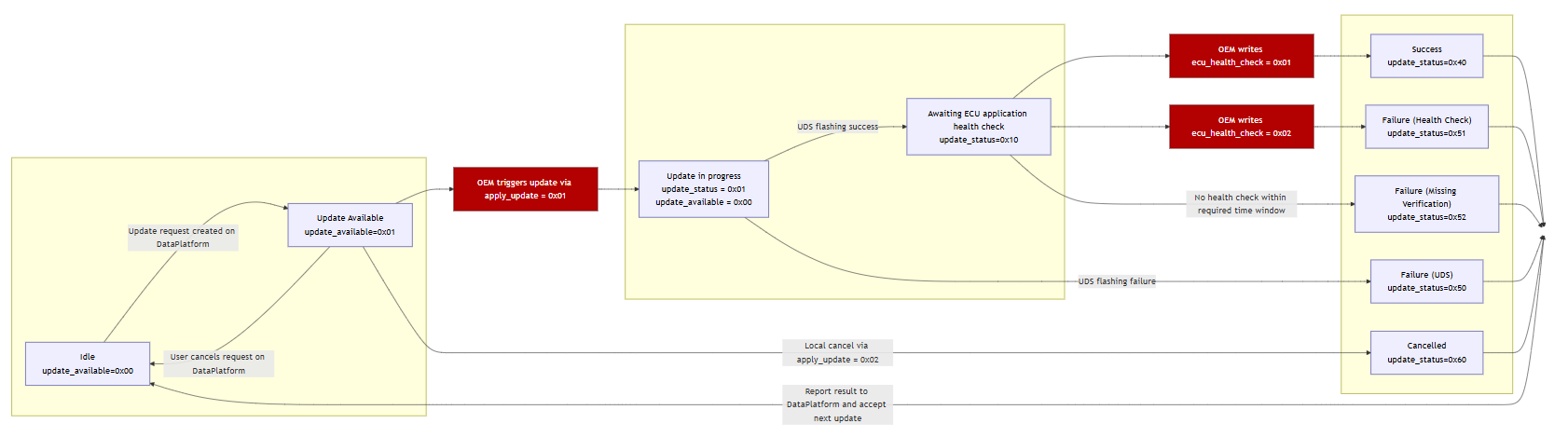
ECU FOTA State Machine
The ECU FOTA workflow transitions through the following states during the update lifecycle.
State Overview
| State | update_status |
Description |
|---|---|---|
| Idle | 0x00 |
No ECU update active |
| Update Available | — | Update available and waiting for operator approval (update_available = 0x01, update_status remains 0x00) |
| Bootloader Transition | 0x01 |
TCU sends bootloader CAN frame and waits configured delay — no dedicated status value; reported as Flashing in progress |
| Flashing | 0x01 |
ECU flashing in progress |
| Waiting for Verification | 0x10 |
OEM application verification pending |
| Successful | 0x40 |
Update completed successfully |
| Flashing Failed | 0x50 |
ECU flashing failed (includes bootloader transition failures) |
| Verification Failed | 0x51 |
OEM application verification failed |
| Verification Timeout | 0x52 |
OEM verification timed out |
| Cancelled | 0x60 |
Update rejected or cancelled — only reachable from Update Available state |
Values ≥ 0x40 are final states. Once a final state is reached, the update cycle is complete and a new ECU update request is required.
CANopen Address Reference
Use the following CAN ID mappings when constructing SDO commands:
| Parameter | Example Value |
|---|---|
TCU node ID (default, CAN1) |
0x27 |
| TCU SDO request CAN ID | 0x627 |
| TCU SDO response CAN ID | 0x5A7 |
| ECU UDS CAN ID (example) | 0x701 |
The TCU communicates with the ECU via UDS over CAN. The ECU UDS CAN ID is included here for reference when verifying CAN traffic during integration — it is not used in the SDO commands to the TCU.
Replace <TCU_CAN_ID> with your actual configured value in all cansend commands below.
The examples below use cansend (Linux SocketCAN).
The same SDO frames can be sent using any CANopen tool, including PCAN View, Vector CANalyzer, or custom CANopen stacks
— the frame content is identical regardless of tool.
Example Workflow
The following cansend commands illustrate a complete successful update sequence.
For full object definitions and valid values, refer to the object descriptions below.
-
Read update availability —
update_availableat0x5FF3:0x01. Response0x01means an update is ready.cansend can1 <TCU_CAN_ID>#40F35F0100000000 -
(Optional) Read update attempts counter —
update_attempts_counterat0x5FF3:0x03. Confirms the update request reached the TCU.cansend can1 <TCU_CAN_ID>#40F35F0300000000 -
Approve the update —
apply_updateat0x5FF3:0x40, write0x01.cansend can1 <TCU_CAN_ID>#2FF35F4001000000 -
Poll update status —
update_statusat0x5FF3:0x50. Poll periodically. Proceed when value is0x10.cansend can1 <TCU_CAN_ID>#40F35F5000000000 -
Report verification result —
ecu_health_checkat0x5FF3:0x60, write0x01. TCU setsupdate_statusto0x40.cansend can1 <TCU_CAN_ID>#2FF35F6001000000 -
Confirm final status — expected response:
0x40(success).cansend can1 <TCU_CAN_ID>#40F35F5000000000
Status Objects
Use these objects to monitor update availability, progress, and execution status.
update_available
| Property | Value |
|---|---|
| Object | 0x5FF3:0x01 |
| Access | read-only |
| Type | UINT8 |
| Persistent | Yes |
Indicates whether an ECU update is available and ready to be applied.
| Value | Meaning |
|---|---|
0x00 |
No update available |
0x01 |
Update available — can be applied via apply_update |
Reset behavior: the TCU resets this object to 0x00 when the update is triggered or cancelled via apply_update, or when cancelled remotely via DataPortal.
update_status
| Property | Value |
|---|---|
| Object | 0x5FF3:0x50 |
| Access | read-only |
| Type | UINT8 |
| Persistent | Yes |
Reports the current or final status of the ECU update operation. The final status remains stored until the next update is initiated via apply_update.
| Value | State | Type |
|---|---|---|
0x00 |
Idle | Transient |
0x01 |
Flashing in progress | Transient |
0x10 |
Waiting for OEM health verification | Transient |
0x40 |
Update successful | Final |
0x50 |
Flashing failed | Final |
0x51 |
Health verification failed | Final |
0x52 |
Verification timeout | Final |
0x60 |
Update cancelled | Final |
Note
Once update_status reaches a final value (≥ 0x40), identification objects (update_request_id, ecu_can_id) and timestamp objects are overwritten when the next update becomes available. See Update Identification Objects.
Typical successful sequence:
0x00 → 0x01 → 0x10 → 0x40
update_status = 0x60 (cancelled) is only reachable from the "Update Available" state — that is, before apply_update = 0x01 has been written. Once flashing has started, local cancellation via apply_update = 0x02 is rejected with SDO abort 0x08000022.
update_attempts_counter
| Property | Value |
|---|---|
| Object | 0x5FF3:0x03 |
| Access | read-only |
| Type | UINT32 |
| Persistent | Yes |
Counts the number of ECU update requests received by the TCU. Increments each time update_available transitions from 0x00 to 0x01. Use this counter to confirm that an update request reached the TCU and to track the total number of updates over the machine lifetime.
Update Identification Objects
These objects identify the current update target and request. They are updated each time a new update becomes available (update_available transitions from 0x00 to 0x01).
Note
Once update_status reaches a final value (≥ 0x40), these objects are overwritten when the next update becomes available. Do not interpret them as information about the update that just completed.
update_request_id
| Property | Value |
|---|---|
| Object | 0x5FF3:0x02 |
| Access | read-only |
| Type | STRING (36 characters) |
| Persistent | Yes |
Globally unique identifier (UUID v4) for the current update request. Provides traceability between DataPlatform, TCU, HMI, and OEM logging systems.
ecu_can_id
| Property | Value |
|---|---|
| Object | 0x5FF3:0x05 |
| Access | read-only |
| Type | UINT32 |
| Persistent | Yes |
The CAN identifier of the ECU targeted by the current firmware update.
Timestamp Objects
The following objects contain UNIX timestamps in seconds (UTC, seconds since 1970-01-01 00:00:00).
update_available_time
| Property | Value |
|---|---|
| Object | 0x5FF3:0x04 |
| Access | read-only |
| Type | UINT32 |
| Persistent | Yes |
Timestamp indicating when the TCU detected and made the update available. This reflects TCU detection time, not the DataPlatform request creation time.
update_start_time
| Property | Value |
|---|---|
| Object | 0x5FF3:0x52 |
| Access | read-only |
| Type | UINT32 |
| Persistent | Yes |
Timestamp indicating when ECU flashing started (when apply_update = 0x01 was accepted).
update_end_time
| Property | Value |
|---|---|
| Object | 0x5FF3:0x53 |
| Access | read-only |
| Type | UINT32 |
| Persistent | Yes |
Timestamp indicating when the ECU update completed, either successfully or with failure. Updated when update_status transitions to a value ≥ 0x40.
Approval and Verification Objects
apply_update
| Property | Value |
|---|---|
| Object | 0x5FF3:0x40 |
| Access | write-only |
| Type | UINT8 |
| Persistent | No |
Approves or rejects a pending ECU update.
| Value | Meaning |
|---|---|
0x00 |
No effect |
0x01 |
Approve — trigger UDS ECU firmware update |
0x02 |
Reject — cancel and delete the pending update |
This object can only be written when update_available = 0x01. Writing a non-zero value while update_available ≠ 0x01 causes the TCU to return SDO abort 0x08000022. Writing 0x00 is always permitted regardless of state and has no effect.
After a non-zero value is accepted:
update_availableresets to0x00- The TCU reports current update status in
update_status
After approval (0x01), the TCU sends the configured bootloader switch CAN frame (if defined), waits the configured delay, then initiates the UDS programming session (0x10 0x02 per ISO 14229).
Warning
The bootloader trigger must only be activated at the correct point in the update workflow. See Configure Electronic Architecture for details.
ecu_health_check
| Property | Value |
|---|---|
| Object | 0x5FF3:0x60 |
| Access | write-only |
| Type | UINT8 |
| Persistent | No |
Reports the OEM-side ECU application verification result after flashing.
| Value | Meaning |
|---|---|
0x00 |
No effect |
0x01 |
Verification successful — TCU sets update_status to 0x40 |
0x02 |
Verification failed — TCU sets update_status to 0x51 |
This object can only be written when update_status = 0x10. Writing a non-zero value in any other state causes the TCU to return SDO abort 0x08000022.
After a non-zero value is accepted, the TCU reflects the outcome in update_status.
update_progress
| Property | Value |
|---|---|
| Object | 0x5FF3:0x51 |
| Access | read-only |
| Type | UINT8 |
| Persistent | No |
Estimated progress of the current update in percent. Resets to 0 when update_available transitions to 0x01. Starts incrementing after apply_update = 0x01 is accepted.
Timeout Object
ecu_health_check_timeout
| Property | Value |
|---|---|
| Object | 0x5FF3:0x62 |
| Access | read/write |
| Type | UNSIGNED16 |
| Unit | minutes |
| Persistent | Yes |
Defines the maximum time in minutes the TCU waits for the OEM to write a health check result after update_status = 0x10. If no result is written within this period, the TCU sets update_status to 0x52.
| Value | Behavior |
|---|---|
0 |
Timeout disabled — TCU waits indefinitely |
1–65535 |
Timeout in minutes (maximum ~45 days) |
Default: 10 minutes.
SDO Abort Conditions
SDO abort code 0x08000022 indicates that data cannot be transferred or stored to the application because of the present device state.
The TCU returns this abort code if:
apply_updateis written when no update is available (update_available ≠ 0x01)ecu_health_checkis written when not in verification state (update_status ≠ 0x10)apply_updateorecu_health_checkis written after flashing has already started or the update is already finalizedapply_updateorecu_health_checkis written when any invalid state transition is attempted
Troubleshooting
| Problem | Possible Cause |
|---|---|
update_available always 0x00 |
No pending ECU update request on DataPortal |
apply_update rejected (SDO abort) |
update_available is not 0x01 |
| Flashing does not start after approval | ECU did not accept UDS session — bootloader transition failed |
update_status remains 0x10 |
OEM verification result not written to ecu_health_check |
Verification timeout (0x52) |
ecu_health_check not written within the configured timeout window |
| Update cancelled unexpectedly | Operator rejected via apply_update = 0x02, or remote cancellation via DataPortal |
Service and Support
The latest versions of the drivers, software, firmware, and documentation are available at Document Library.
Do you need help or want to report a bug?
Visit Proemion for more information, or raise a ticket via Support.
Firmware Updates and Support
To ensure the best performance and security of your devices, we strongly recommend always installing the latest firmware provided by Proemion.
Please note:
We do not provide technical support for issues caused by outdated firmware.
Errors resulting from outdated firmware are considered non-qualified errors and are not covered by warranty or support.
Regular firmware updates are essential to maintaining the functionality of your devices.
If you need assistance with the update process, please contact our Service and Support.
For more information on the Firmware Update, check the device manual of your device at the Document Library.