Configure the Electronic Architecture
An Electronic Architecture (EA) tells the system which ECUs are installed on a specific machine type, how to reach them on the CAN bus, and which firmware is compatible with each — so the right firmware is always deployed to the right controller. It serves as a reference architecture for a machine platform: all machines of the same type share the same Electronic Architecture.
Once configured, the EA is assigned to individual machines so the system knows which ECUs can be updated and how to reach them.
flowchart TD
    EA["Electronic Architecture<br/>e.g. Excavator-X200"]
    ECU1["ECU Definition<br/>e.g. Hydraulics Controller<br/>Brand: TTControl / Model: TTC 2390"]
    ECU2["ECU Definition<br/>e.g. Drive Controller<br/>Brand: Bosch Rexroth / Model: BODAS RC5-6/40"]
    REPO1["Software Repository<br/>Brand: TTControl / Model: TTC 2390"]
    REPO2["Software Repository<br/>Brand: Bosch Rexroth / Model: BODAS RC5-6/40"]
    M1["Machine<br/>Unit #1001"]
    M2["Machine<br/>Unit #1002"]
    EA --> ECU1
    EA --> ECU2
    ECU1 -.->|"Brand/Model match"| REPO1
    ECU2 -.->|"Brand/Model match"| REPO2
    EA --> M1
    EA --> M2
The Electronic Architecture must be configured before ECU update requests can be executed.
Step 1 - Create the Electronic Architecture
-
Navigate to Settings > ECU Management > Electronic Architectures.
-
Click Create Architecture in the top right corner.
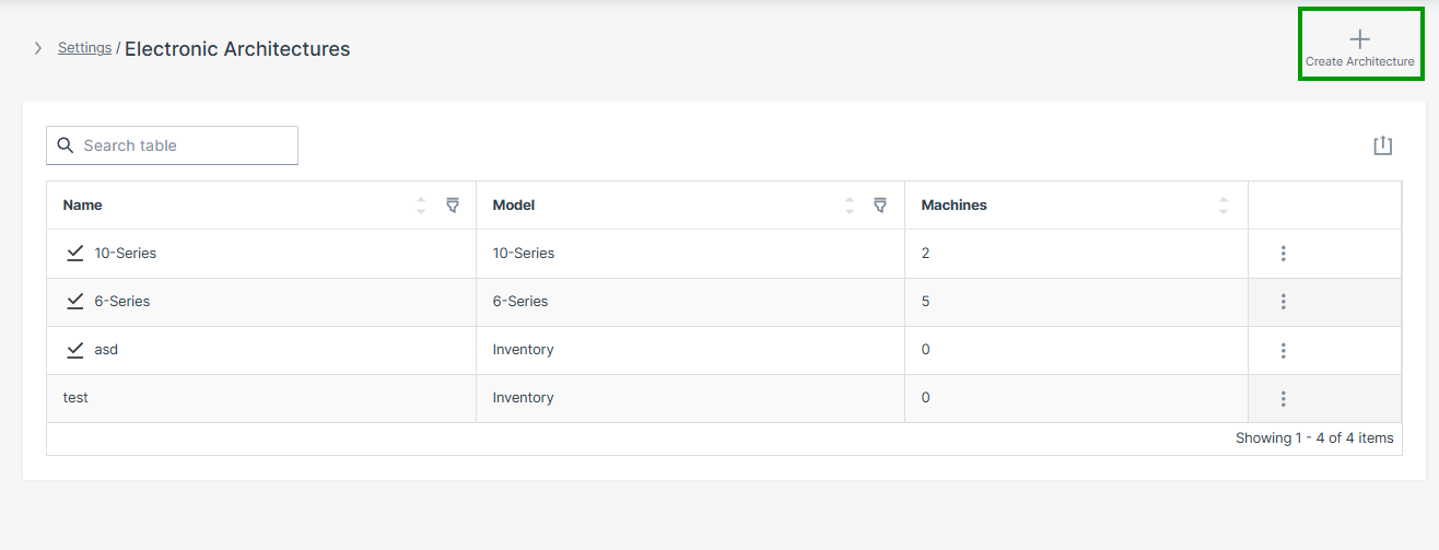
Figure 1: Electronic Architectures Overview -
Enter the following and click Create:
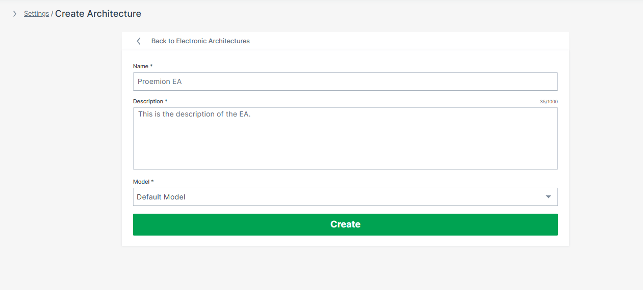
Figure 2: Create Architecture
| Field | Description |
|---|---|
| Name | A descriptive name for this machine type, e.g. Excavator-X200 |
| Description | A description of this architecture |
| Model | The machine model this EA applies to, selected from a dropdown list |
The Electronic Architecture is now successfully created.
Step 2 - Add an ECU Definition
Each ECU to be updated via ECU FOTA must be added to the Electronic Architecture individually. The ECU definition is configured in four-steps: ECU info > Connection info > Bootloader configuration > Authentication.
-
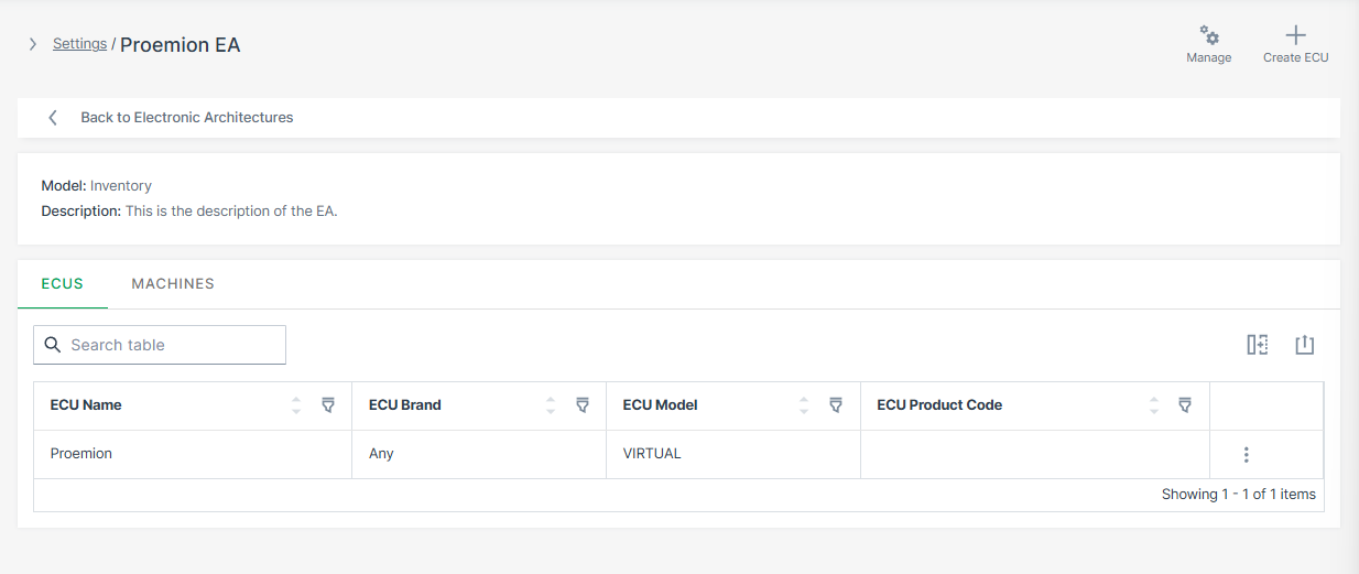
In the newly created EA, click Create ECU in the top right corner.
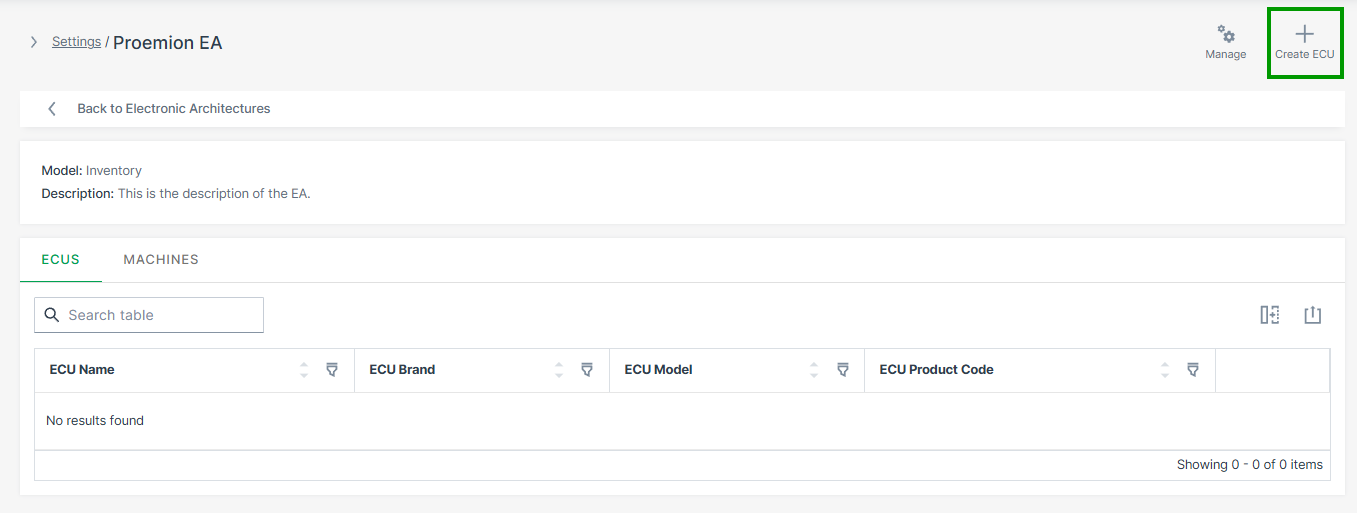
Figure 3: Create ECU -
Enter the ECU info and click Continue:
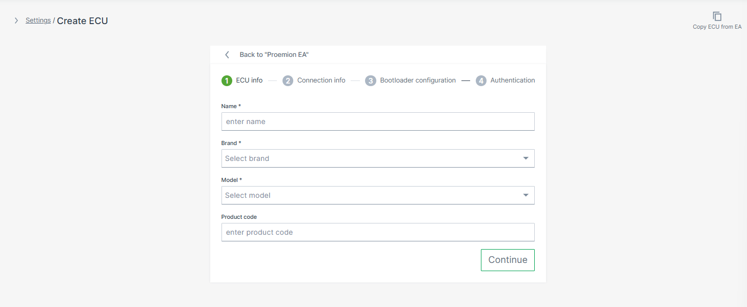
Figure 4: ECU Info Field Description Name A descriptive name for this ECU, e.g. Hydraulics ControllerBrand ECU manufacturer, selected from dropdown list — must match the Brand of the Software Repository Model ECU model identifier, selected from dropdown list — must match the Model of the Software Repository Product Code Optional reference to your ERP system -
Enter the Connection info and click Continue:
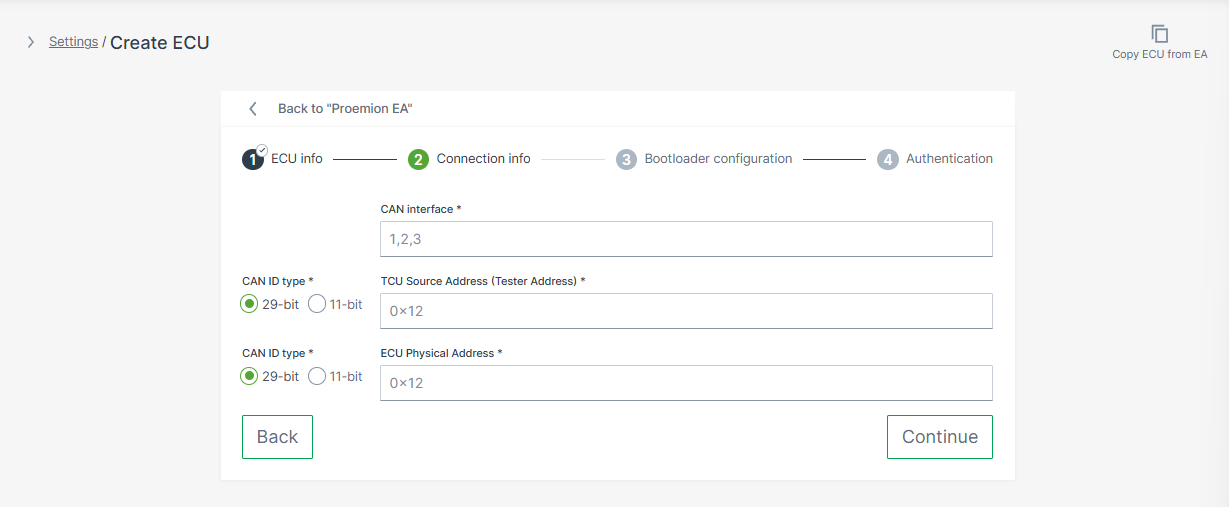
Figure 5: Connection Info Warning
Enter the ECU's bootloader addresses here — not its normal operating (application) addresses. The bootloader address is the address the ECU uses during programming mode, which is different from the address used during normal operation. Using the wrong address type will prevent flashing from starting. The correct bootloader address is provided by the ECU manufacturer.
Field Description CAN Interface The physical CAN port on the TCU this ECU is connected to: 1,2, or3. Must match the actual machine wiring.CAN ID Type 11-bitor29-bit— set independently for TCU Source Address and ECU Physical AddressTCU Source Address The CAN ID the TCU uses to send diagnostic requests (tester address). Default: 0x7E0(11-bit)ECU Physical Address The CAN ID of the ECU in bootloader mode. Default values: TTC controllers: 0x7E7or0x7EF(11-bit); Bosch Rexroth controllers:0x18DA01FAor0x18DAFA01(29-bit) -
Optionally, enter the Bootloader configuration:
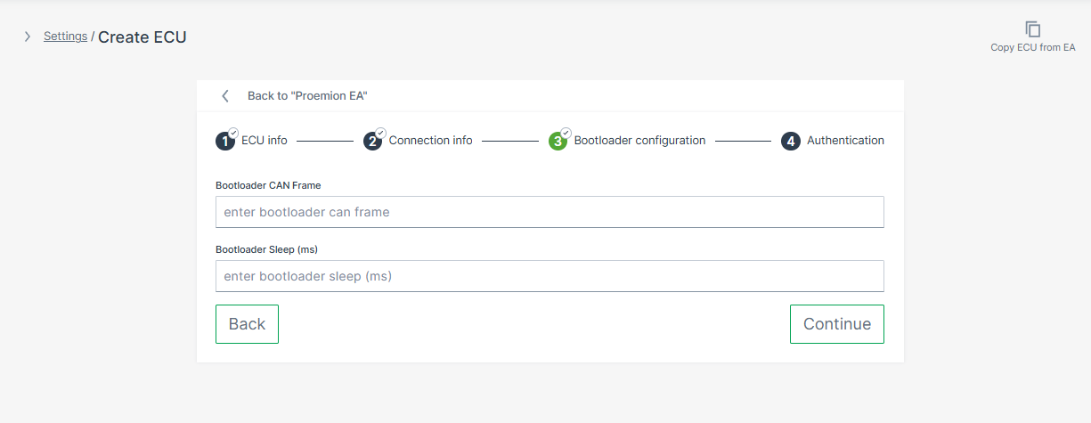
Figure 6: Bootloader Configuration Some ECUs require a specific CAN message to switch into programming mode before flashing can begin. If your ECU requires this, configure the Bootloader CAN Frame and Bootloader Sleep fields.
Whether your ECU requires a bootloader trigger depends on the ECU type:
- Bosch Rexroth controllers — no external trigger is required. The bootloader switch is handled within the standard UDS programming sequence.
- TTC controllers — the OEM defines the trigger via the TTC SDK. The CAN frame is not specified by TTC; it can be any application-defined CAN message.
When configured, the TCU sends the bootloader CAN frame, waits the specified delay, and then starts the UDS programming session. If no trigger is required, leave both fields empty.
Warning
The bootloader trigger must only be active after
update_available = 0x01and the operator has writtenapply_update = 0x01. Any earlier attempts to switch the ECU into bootloader mode must be ignored by the ECU. This applies to both TTC and Bosch Rexroth controllers.Field Description Bootloader CAN Frame CAN frame sent to switch the ECU into bootloader mode before flashing. Uses cansendformat:CANID#DATAwhere the CAN ID is in hexadecimal and DATA is a sequence of hex bytes, e.g.01111111#0100000000000000. Provided by the ECU manufacturer.Bootloader Sleep (ms) Delay in milliseconds the TCU waits after sending the bootloader frame before initiating the UDS programming session, e.g. 500. -
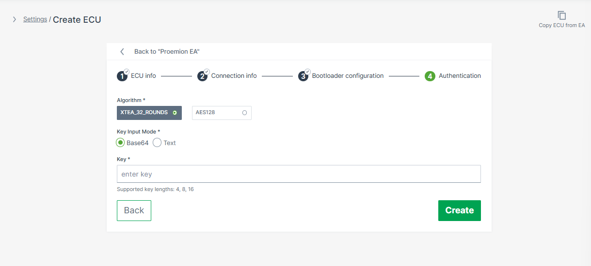
Enter the Authentication credentials and click Create:
| Field | Options |
|---|---|
| Algorithm | XTEA_32_ROUNDS or AES128 — supported algorithms depend on the ECU model |
| Key Input Mode | Base64 or Text — use Base64 for keys containing non-printable bytes |
| Key | Authentication key — supported lengths: 4, 8, or 16 bytes. The key is treated as a password and cannot be retrieved via the UI or API after saving. |
The ECU definition is now part of the Electronic Architecture.
Repeat Step 2 for each additional ECU in this architecture.
Step 3 - Assign Machines
After all ECU definitions are configured, assign the target machines to the EA. This tells the system which physical machines use this ECU topology.
-
Select the EA you want to assign to a machine from the EA page.
-
Select the Machines tab and click Manage Machines.
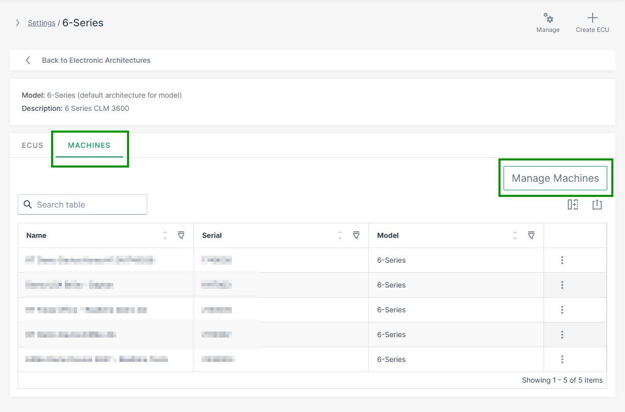
Figure 8: Assign Machine to EA -
Select the target machines and click Save.
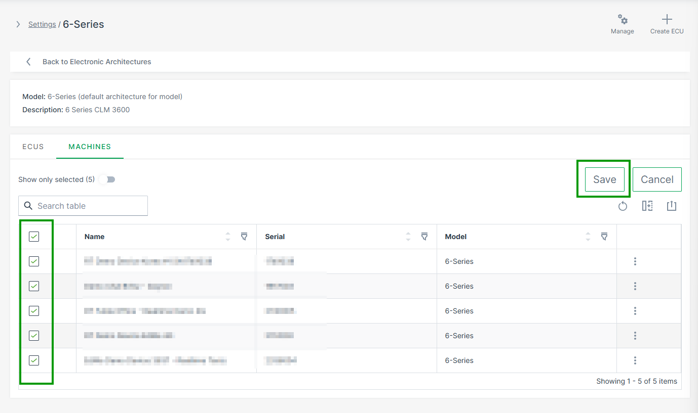
Figure 9: Select Machines
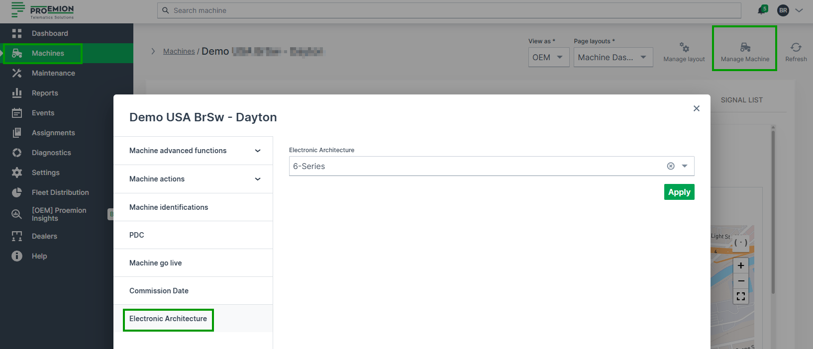
Alternatively, you can also assign machines to the EA via the Manage Machine Dialog.
Go to Machine Page > Manage Machine > Electronic Architecture.
Validation
Before creating ECU update requests, verify the configuration is complete:
| Check | How to verify |
|---|---|
| ECU visible in architecture | ECU appears in the architecture's ECU list |
| Repository assigned and matching | Repository is shown next to the ECU with no mismatch warning |
| CAN IDs configured | Request and Response CAN IDs are filled in |
| Machine assigned to EA | Machine appears in the architecture's machine list |
| ECU FOTA enabled on TCU | Confirmed by Proemion during onboarding |
Troubleshooting
| Problem | Possible Cause |
|---|---|
| ECU missing in machine | Electronic Architecture not assigned to machine |
| Repository mismatch warning | ECU Brand or Model does not match the Software Repository |
| Machine not visible | Machine not yet assigned to the Electronic Architecture |