Display 1001 Manual
About the Display 1001
The Display 1001 is an all-purpose display which has been developed for use in harsh industrial applications with high electrical or mechanical requirements. Display 1001 can visualize data on the CAN bus. The display unit is equipped with 3 switches, a buzzer, LED-backlight for the keyboard and a 2 x 8 character LCD display. Data can be exchanged via the CAN bus.
The Display Configurator software tool will assist you with the development of your application. With its interface, you can design your user interface without any special programming knowledge. You can see what your display configuration will look like later on when displayed by the display unit.
General
Legal Requirements
Safety instructions
These instructions are part of the device. They contain text and illustrations for the correct handling of the module and must be read before installation or use.
Adhere to the information in the documentation. Non-observance of the instructions, operation that is not in accordance with the use as prescribed below, and incorrect installation or handling can affect the safety of people and equipment.
The device must be installed, connected, and commissioned by a qualified electrician. Disconnect the device externally before handling it. Disconnect any independently supplied output load circuits as well.
As no components to be maintained by the user are contained in the device, the housing must not be opened. The device can only be repaired by the manufacturer. The device must be disposed of in accordance with national environmental regulations.
In the case of malfunctions or uncertainties, please contact the manufacturer. Tampering with the device can seriously affect the safety of people and equipment. This is not permitted and leads to an exclusion of liability and warranty.
This device is designed to be used in systems which must be checked for conformity with legal requirements prior to commissioning. The integrator of this device is responsible for checking that the device complies with regional directives and requirements.
Proemion assumes no liability for the use of any information contained in this manual and does not guarantee that the manual is free of patent infringement. Proemion neither conveys any license under its patent rights nor under the rights of others.
Export
This device requires the explicit permission of the manufacturer in order to be exported to the USA.
Important information for using Display 1001
Warning
This device is designed to be used in systems which must be checked for conformity with legal requirements prior to placing the device into operation. The integrator of this device is responsible for checking that the device complies with regional directives and requirements.
Proemion assumes no liability for the use of any information contained in this manual and does not guarantee that the manual is free of patent infringement. Proemion neither conveys any license under its patent rights nor under the rights of others.
The type label must not come into contact with any kind of solvent-containing substance.
The device may only be installed, connected, and commissioned by qualified personnel. Disconnect the device externally before doing any work on it. If necessary, disconnect separately supplied output circuits as well.
Operation
The device must not be operated in machines and applications where life depends on the device operating properly.
Disposal
Observe your national regulations when disposing of the device and its package.
Installation
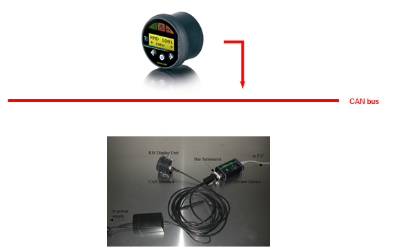
Connect the Display with the right cable to the CAN bus.
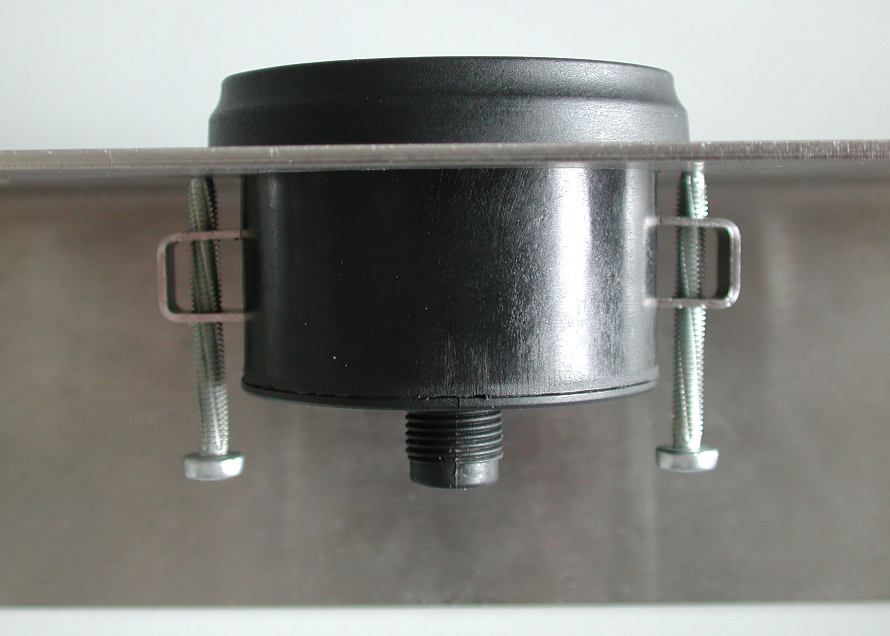
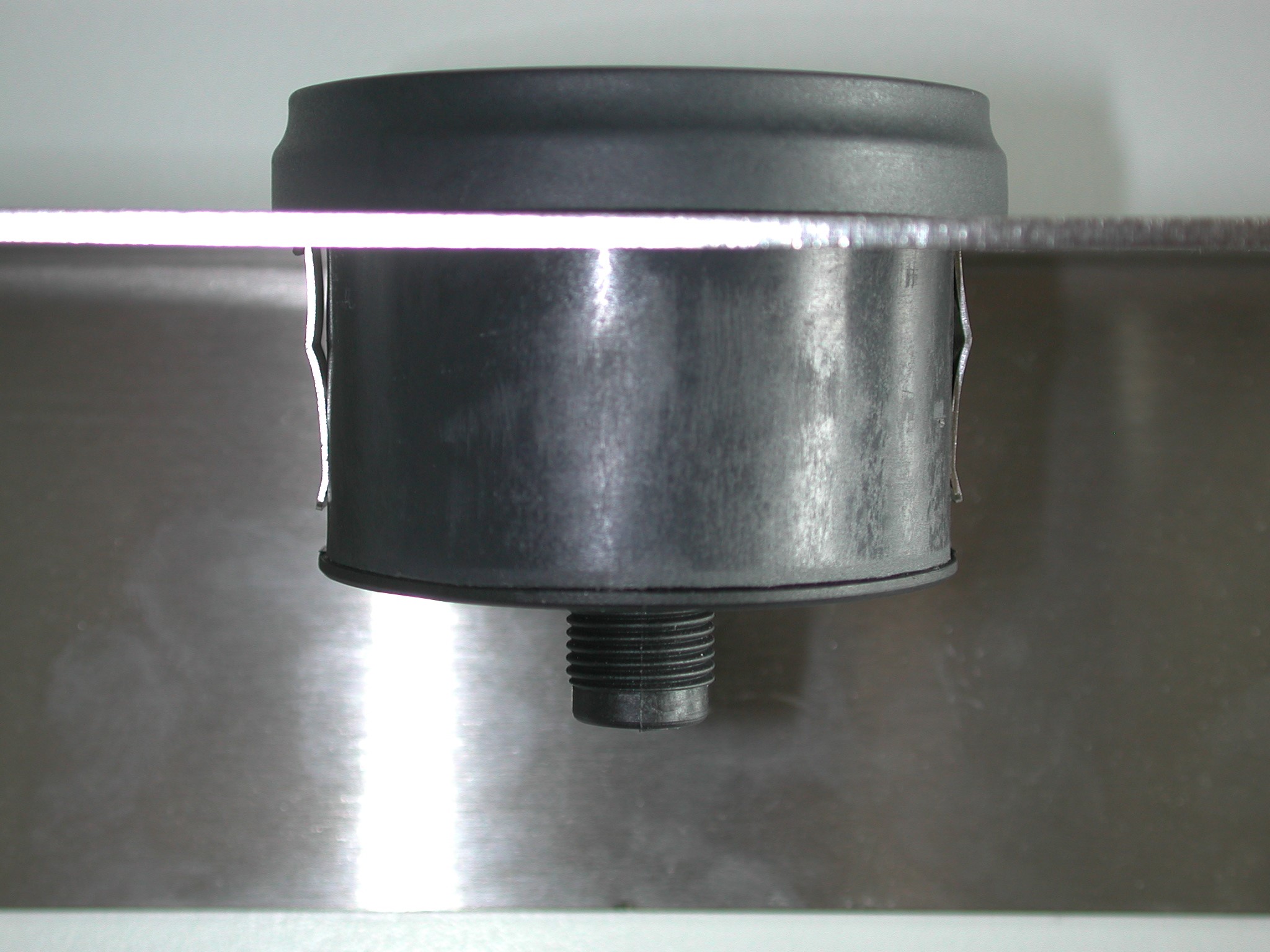
Mounting
There are two different ways of mounting the Display 1001:
Configuration
After all components have been installed, you can configure the display with the Display Configurator software.
Connectors
The Display 1001 is equipped with the following connector:
The 5-pin male power/CAN connector is used to supply the Display 1001 with a voltage of 9V to 60V and to connect it to a CAN bus.
The drawing below shows an overview of the explained hardware component:
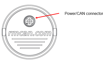
Power/CAN Connector
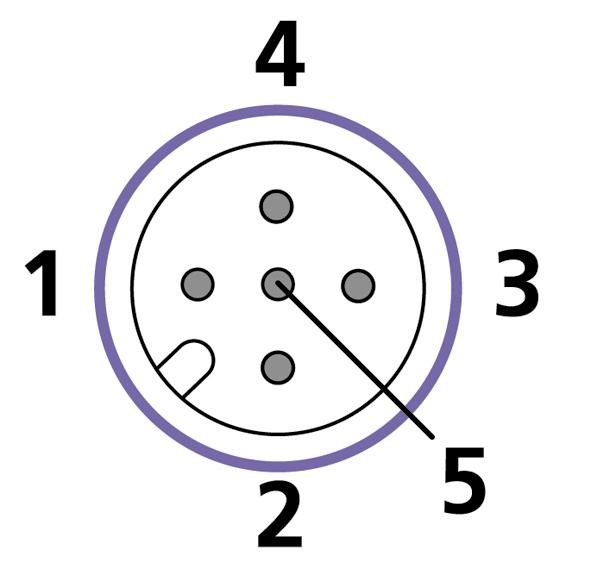
Apart from connecting Display to the power supply, the two power/CAN connectors connect your display to the CAN bus. The pin assignment of the power/CAN connector is shown in the table and drawing below.
| Function | Pin |
|---|---|
| Ground | 1 |
| VCC (9 V – 60 V) | 2 |
| CAN GND (internally connected to Ground !) | 3 |
| CAN H | 4 |
| CAN L | 5 |
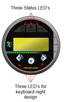
LEDs and Buzzer
LEDs
| LED | Description |
|---|---|
| Status LEDs | Status information can be displayed |
| LEDs for keyboard night design | LEDs can be switched on or off |
Buzzer
The buzzer signals bus off conditions by chirping.
It can alternatively be switched off/on by sending certain CAN messages to the display.
Repair Mode
If the DOD download to the Display Unit is interrupted or corrupted, the display unit will power on and reset constantly.
Each display unit comes with a certain key combination, which when pressed will send your display unit into Repair Mode in which the DOD download can be repeated.
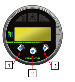
This mode can be activated by pressing keys 1 and 3 simultaneously while making a power reset (by removing and replacing the power source).
The display will be reset to Node ID 1 and baudrate 250kbit.
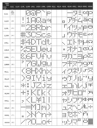
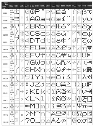
Character maps
Warning
Consider that there are two different character maps in use.
Since serial production start up to Revision 2.0.0, the English/Japanese character map has been used.
From Revision 2.1.0 or later will come together with the English/European character map.
Temperature behavior on LCD Modules
The Display 1001 has a LCD module with an operational temperature range specified from –20° to +70° Celsius. This temperature range is correct and has been verified by RM.
Nearly every type of LCD module has special behavior in cold environments: As temperatures decrease, the speed at which the LCD fluid may change state gets slower and slower.
This is a normal effect, characteristic to the technology.
With our PC Software Tool, the Display Configurator, there is a special feature supported by the Display 1001 called “news ticker functionality” to create moving texts.
This function is working correctly over the complete temperature range, but because of the slow LCD fluid an operator may no longer read this moving text effectively in very cold environments.
Be aware of this behavior and use of this function only down to –3° Celsius.
Technical Data
| Value | Description |
|---|---|
| Supply voltage (V+) | 9 V – 60 V DC |
| Current consumption | < 100 mA @ 24 V (external fuse necessary, depending on supply voltage) |
| Operating temperature | -20 °C … +70 °C |
| IP rating | IP65 frontside |
| Display type | 2x8 character LCD display green/yellow Backlight |
| LED | 3 Status LEDs |
| Operator keys | 3 illuminated switches |
| More features | Buzzer |
| Controller | 8-bit microcontroller |
| Flash memory size | 96 KB |
| SRAM size | 3.3 KB |
| EEPROM size | 64 KB |
| CAN specification | 2.0 B |
| CAN bus coupling | According to ISO 11898, high speed |
| Maximum baud rate | 1 Mbit/s |
| CAN protocols | CANopen SAE J1939 Layer 2 |
| Order number | 251007020 |
| Accessories | |
| 136000009 CAN Cable 5-Pin M12 | |
| 5-pin plug and D-Sub-9 plug 2 m | |
| 140 700 003 Gasket for Display | |
| Standard housing | Plastic |
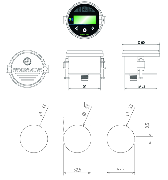
| Dimensions in mm | average: 60/49 |
| Weight in grams | 63 |
Technical Drawings