Basic Configuration - TCU
Introduction
In this chapter you will learn how to:
- create a new CANlink® mobile configuration
- configure the TCU to receive CAN messages with a particular CAN ID
- reduce the number of CAN messages received by the TCU for further processing, using cyclic input downsampling
- configure the TCU to prepare processed CAN messages for sending to the Proemion DataPlatform
- write the configuration to the TCU
- configure the DataPlatform to decode the received CAN message bytes as a signal
- send test CAN data to the TCU
- force the TCU to transmit pending data to the Proemion DataPortal
- view the test data on the Proemion DataPortal
- observe and monitor the time it takes for transmitted data to show up on the DataPortal
The Setup
The PCAN-USB interface is connected to CAN interface #1 of the CANlink® mobile. The controller CAN baud rate is 250 kbit/s.
Don't forget the 120 Ω terminator resistor between the PCAN-USB interface and the CANlink® mobile.
The following signal will be transmitted from the PCAN-USB interface.
| ELEMENT | VALUE |
|---|---|
| ACRONYM | fuel_level |
| LABEL | Fuel Level |
| INTERFACE | CAN1 |
| FORMAT | STANDARD_11_BIT |
| CAN ID | 0x200 |
| START BIT | 0 |
| BIT-LENGTH | 8 |
| DATA TYPE | UNSIGNED_INT |
| SCALING | None |
| OFFSET | None |
| UNIT | PERCENTAGE_POINT |
| MIN VALUE | 0 |
| MAX VALUE | 100 |
| CAN TX RATE | 1/sec |
Analysis
The fuel level signal is transmitted on the CAN bus once per second. If we were to send to the DataPlatform every single value transmitted onto the CAN bus, it would be 1 byte per sec x 60 sec x 60 min = 3,600 byte per hour. Let's assume a machine works for 250 hours a month, and that brings us to
3,600 bytes per hour x 250 hours per month = 900,000 bytes per month.
We've transferred almost a megabyte of data in a month for a single machine. Now think about adding a timestamp (which is mandatory), 50 more signals, some of which have very high transmission rates (e.g. engine speed every 50ms typically), and multiply by 1000 machines (or the size of your fleet), and the data volume requirements become astronomical.
This not only results in very high cost for data transmission to and storage at the DataPlatform (or any server for that matter), but it also makes it very slow to process the data, e.g. displaying a graph or feeding it into a data science pipeline.
For this reason, it is very important to carefully consider how much data to actually transmit to the DataPlatform. The right answer for this is found by understanding the behavioral profile of each signal and keeping only the data that is actually valuable.
Cyclic Downsampling
One method of reducing the amount of data transmitted to the DataPlatform is by applying downsampling at the CAN input of the CANlink® mobile, such that only a single CAN message can be received every x milliseconds, where x is the configured downsampling input suspension time.
Since fuel level doesn't change very rapidly, let's downsample it to one message per minute. That would be 1 byte per min x 60 min = 60 bytes per hour x 250 hours per month = 15,000 bytes per month, which is a reduction by a factor of 60 compared to the non-downsampled fuel level.
TCU Configuration
To configure the CANlink® mobile, create a DOD using the Proemion Configurator.
Device Type
The first step is to determine the type of the CANlink® mobile at hand, which is found on the front label of the device next to the TYPE: item. In older models that do not have a TYPE: item, the type is the rightmost part of the MODEL: item.

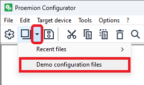
Create New Configuration
The easiest way to start a configuration project is to load one of the demo DODs bundled in the Proemion Configurator. Those named as clm####_PROEMION_Default.DOD are essentially templates that include the most useful Device Variables and DOD parameter groups.
Warning
If you make any changes and save them, the demo/template DOD will now contain the newly made changes. To avoid overwriting the demo DOD, after opening it, immediately invoke a Menu bar > File > Save as... operation to create your own. But if you do need to recover any of the original demo/template DOD files, they are available in the Download Center.
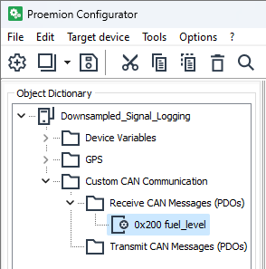
Add Rx Message Object
When developing DODs, a common operation is to bring up the context menu for an item in the Object Dictionary via a right click. From now on whenever you see a context menu, you know how to bring it up!
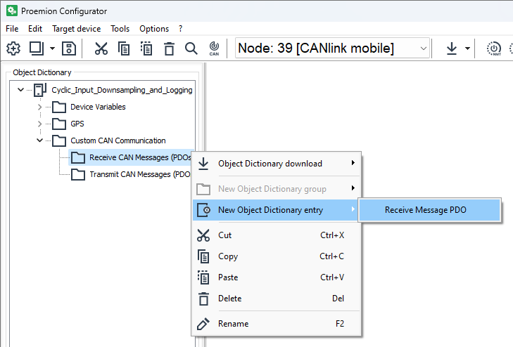
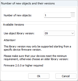
Go ahead with the defaults.
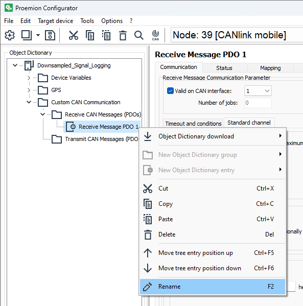
Rename Rx Message Object
When developing DODs, good housekeeping is very important. A good way to name your rx message objects is by using the CAN ID and the acronym. Of course, depending on the project, naming could be different. 0x200 fuel_level will do for now.
Configure Rx Message Object
Each Rx Message Object offers a set of procedures executed in order, for each received CAN message with CAN ID that is accepted by the object's configuration.
For convenience, below are the relevant signal elements we will be configuring in the DOD.
| ELEMENT | VALUE |
|---|---|
| ACRONYM | fuel_level |
| INTERFACE | CAN1 |
| FORMAT | STANDARD_11_BIT |
| CAN ID | 0x200 |
| START BIT | 0 |
| BIT-LENGTH | 8 |
| CAN TX RATE | 1/sec |
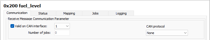
Communication Parameters
Since the controller is connected to the CANlink® mobile on CAN interface #1, Valid on CAN interface=1 is straightforward.
But what about CAN protocol=None? It means only single frame messages are received with CAN ID 0x200, i.e. we only need to use the Standard Channel. The other settings, namely J1939 and OBD2 are for receiving multi frame messages that use the J1939 Transport Protocol or ISO 15765-2 (ISO-TP).
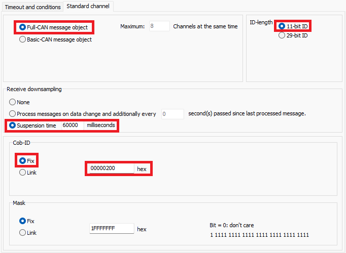
A Full-CAN message object, which means received message filtering is done in hardware (the processor doesn't need to be interrupted every time message is received). The CANlink® mobile has 8 hardware receive channels that can be used simultaneously, but more on this topic in another tutorial.
The standard frame format is selected by ID-length=11-bit ID.
Earlier on we decided to downsample fuel_level to one message per minute, so let's set Suspension time=60_000 milliseconds
Finally, set Cob-ID=0x200 to configure this Rx object to process CAN messages containing the fuel_level signal.
If you haven't come across the term COB-ID before, you can take a look at the CANopen PDO protocol
. But if you don't use CANopen, it is safe to think of Cob-ID as the CAN ID.
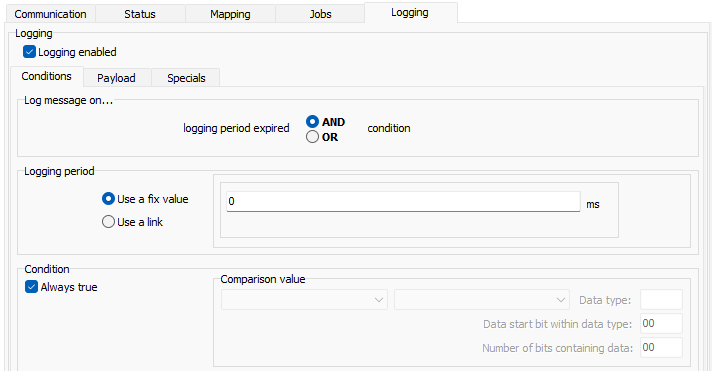
Logging
The messages that get accepted by the Communication Parameters (CAN ID selection and downsampling) are passed onto the next sub-procedures of the rx message object.
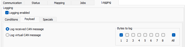
In this example we simply want to log all accepted messages, i.e. transmit all accepted messages to the DataPlatform. This is achieved by setting Logging enabled without any additional logging conditions.
It is more efficient to only log the data bytes with useful data, which is only the first byte in our example.
Send Configuration to TCU
The last step is to send the configuration to the TCU. This is normally done remotely, but on the bench test setup it is better to send it via CAN, which is quicker, and it doesn't consume any mobile data. Data consumption is rarely a problem, but it could be so, if we send a configuration 100 times to the same TCU, once for each time a small change is made.
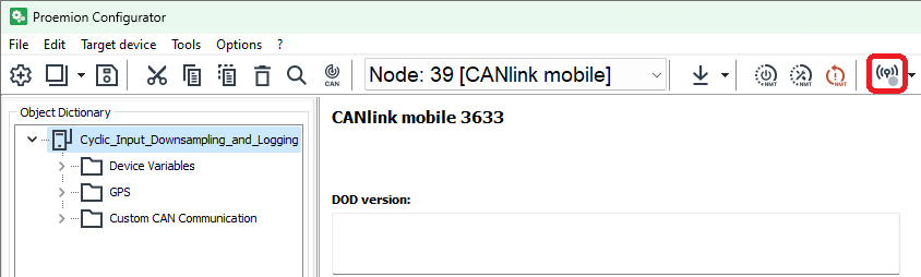
Access the CAN bus
Bring up the communication settings.
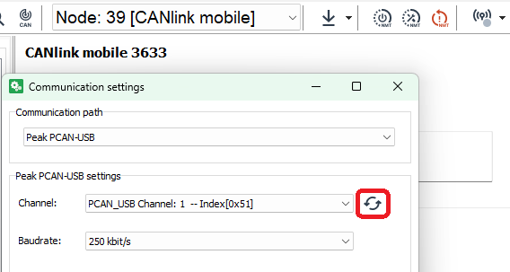
And set Communication path=Peak PCAN-USB, Channel=PCAN_USB Channel: 1 and Baudrate=250 kbit/s.
Warning
The Proemion Configuration will not be able to connect to the PCAN-USB interface if another software application has opened the CAN channel. Close the channel on any other application before proceeding.
Note
If the Channel dropdown menu is blank click on the "refresh" icon on the right.
Info
The default CAN baud rate for all Proemion devices is 250 kbit/s.
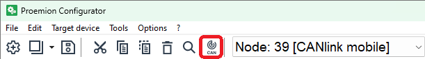
If it all went well, the Communication Settings icon should indicate so with a green virtual LED.

Find the TCU
Run the node scan interface.
Start node scan should find the TCU.
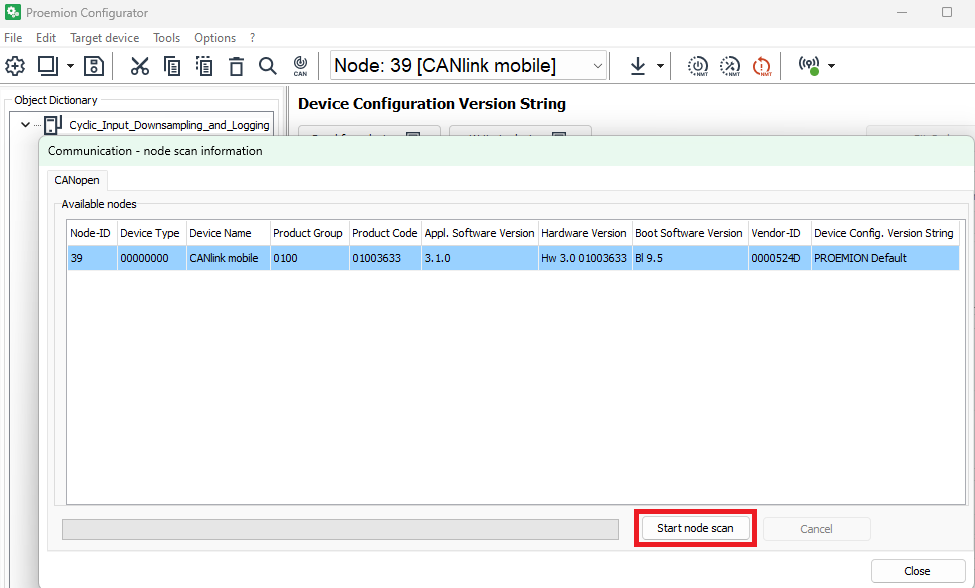
Note
If the node scan does not yield and results, most probably the 120 Ω terminator resistor has not been connected, or the TCU's CAN baud rate cas been configured to a different value from the default.
Info
The CANlink® mobile has a different default CANopen Node ID for each one of its CAN interfaces. Node ID 39 for CAN1, 40 for CAN2, and 41 for CAN3.
Write Configuration to TCU
Write the configuration to the TCU.

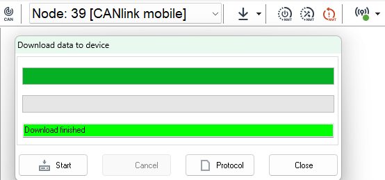
Perform a reset node operation to activate the newly downloaded configuration (a hard reset will have the same effect).
