1. Preamble
1.1. Legal Notice
All brands and trademarks named in this document and possibly protected by third-party rights are subject without limitation to the terms of the valid trademark law and intellectual property rights of their respective registered owner.
You can find a list of the free-source and open-source software as well as copyright notes, license texts and, if applicable, the relevant source code on our website under the link: Free & Open Source Software
Observe all local and regional laws and provisions as well as the safety instructions contained in this document.
1.2. Contact
Proemion GmbH
Donaustr. 14
36043 Fulda, Germany
Phone: +49 661 9490-0
Fax: +49 661 9490-111
info@proemion.com
Proemion Corp.
US Subsidiary
241 Taylor St., Suite 301
Dayton, Ohio 45402, USA
Phone: +1 937 558 2211
Fax: +1 937 641 8787
info-dayton@proemion.com
Proemion Ltd.
373 Gangnam-daero Seocho-gu
Seoul, 06621, South Korea
Phone: +82 2 6080 9490
Fax: +82 504 484 9490
info-seoul@proemion.com
Website: Proemion
1.3. About This Manual
This document is part of the product and provides important information on the intended use, safety, installation, and operation of the devices described below. The document is intended for qualified technicians and electricians with advanced knowledge in electrical engineering and field bus systems, allowing them to estimate the risks and hazards of operating the device and to integrate it into systems with components of other manufacturers.
1.3.1. Safety Levels
The safety levels have the following meanings:
|
Severe injury or death. Probability: very high |
|
Severe injury or death. Probability: possible |
|
Slight or medium injury. Probability: possible |
|
Property damage. |
1.3.2. Symbols and formatting
The following symbols and formatting help you recognize the purpose of the
paragraphs:
|
|
|
|
|
|
| Symbol | Description |
|---|---|
|
Application options for the devices described. |
|
Indicates references to other documents, websites, etc. |
|
Description of different types. Data and descriptions that only apply to certain types are either covered in separate chapters or marked with the symbol shown here. |


2. About the Device
This chapter provides an overview of the device’s operating elements and functions as well as the intended use of the device. Additionally, it provides an overview of the available types and certificates.
For more detailed information, see Chapter Annex.
2.1. Important Device Information
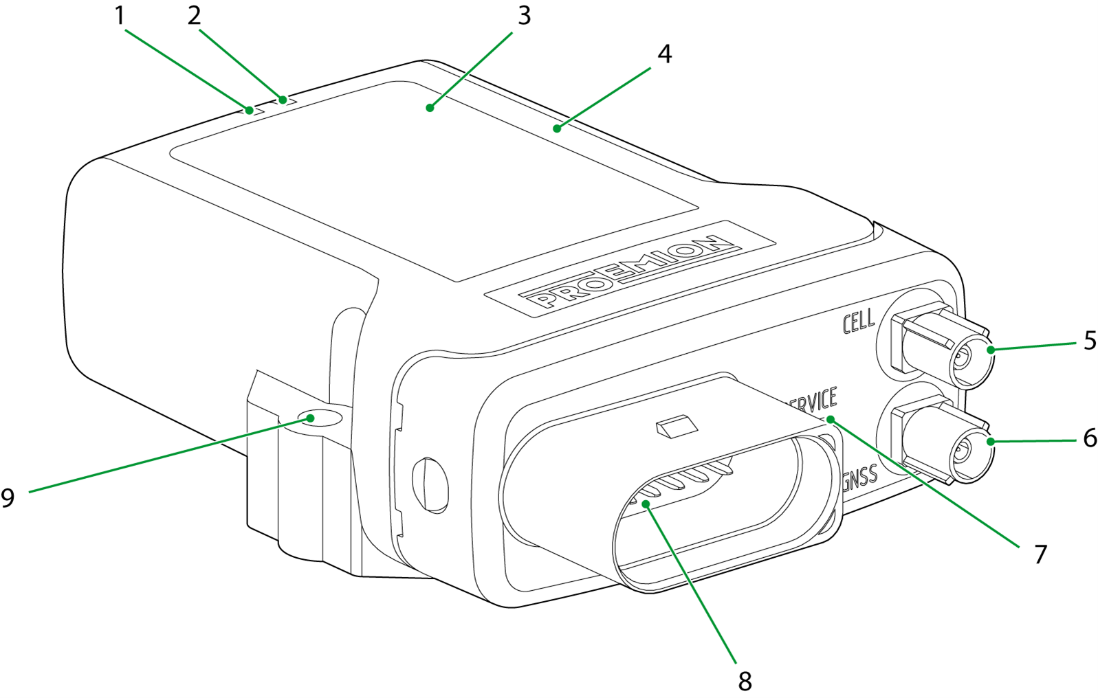
2.1.1. Device Elements
| # | Item |
|---|---|
1 |
ON LED |
2 |
STATUS LED |
3 |
Type label |
4 |
Housing |
5 |
Mobile radio antenna connector |
6 |
GNSS antenna connector |
7 |
Micro-USB port with protective plug / sticker |
8 |
Main plug connector |
9 |
Fixing holes |
|
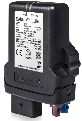
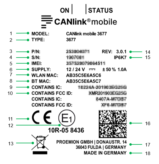
2.1.2. Type Label
The device type label is located on the front of the housing and provides the following information:
| # | Item |
|---|---|
1 |
Model designation |
2 |
Type |
3 |
Part number |
4 |
Serial Number |
5 |
IMEI number |
6 |
Power supply |
7 |
WLAN MAC address |
8 |
Bluetooth MAC address |
9 |
IC-ID |
10 |
FCC-ID |
11 |
CE mark |
12 |
ECE certification mark |
13 |
Disposal symbol |
14 |
Hardware version |
15 |
Protection class |
16 |
|
17 |
Manufacturer address |
18 |
Country of origin |
|
Traceability code
The traceability code contains the following information.
Example:
253004059000000000001815014(I)357520074597168(W)D4CA6E7D0CAA(B)D4CA6E7D0CA9
| Item | Description |
|---|---|
9-digit part number: |
|
Serial number 0-padded: |
|
|
|
|
|
|
|
|
2.1.3. Intended Use
The device is used for the wireless transmission of CAN data from a vehicle or machine according to the 2G, 3G and 4G standards. Depending on the type, GPRS, EDGE, HSPA and LTE can be supported.
Depending on the type, you can also receive and transmit GNSS positioning data and CAN data via the additional Bluetooth, WLAN or LTE interfaces.
The device enables access to CAN data in various modes:
-
CAN-CAN Bluetooth bridge: wireless transmission of CAN data between two CANlink mobile devices, e.g. as a substitute for CAN cables in cable carriers or with remote-control devices.
-
CAN-Bluetooth interface: wireless transmission of CAN data to a Bluetooth terminal device.
-
CAN-WLAN interface: wireless transmission of CAN data to a WLAN.
In interface mode, CAN data can be transmitted to other devices, such as PCs, smartphones or tablets, for display or evaluation.
Depending on the type, the device is equipped with an integrated battery and external antenna ports. The integrated battery provides temporary backup in the event of power failure. It is not intended as a permanent power source for the device. You can connect a GNSS antenna and a mobile communications antenna to the external antenna ports.
The device is suitable for use in mobile and stationary systems for industry, small businesses, and in agricultural and forestry machinery.
The device can be used in environments that require protection class IP6K7.
|
Only use the device within the permitted temperature range and the other parameters specified in the technical data.
Any use other than that described under “Intended use” is considered unintended use.
MISUSE
The device does not comply with Directive 2014/34/EU and may not be used in potentially explosive areas.
The device must not be cleaned with a pressure washer.
QUALIFIED PERSONNEL
The device must only be put into operation by qualified technicians and electricians with advanced knowledge of electrical engineering and fieldbus systems.
The specialist personnel must know the contents of this manual and always have access to it.
|
|
2.1.4. Conformity
For details of the corresponding approval tests, see Certification and Qualification.
The device meets the requirements of the following standards and legal requirements:
|
CE Compliant |

|
UKCA Compliant |

|
ISED Compliant |

|
FCC Compliant |

|
E1 Compliant |

|
2.2. Device Functions
The available types differ according to the provided interfaces.
With the device, you can log position data and transmit and receive CAN data via a mobile phone network. The CAN data can be transmitted directly (RealTime mode) or it can be logged and transmitted at a later time. In logging mode, the CAN data is saved to the device and can subsequently be transmitted.
The device can optionally be ordered with the following equipment features:
-
wireless module for WLAN and Bluetooth
-
an integrated battery
-
external antenna ports for mobile radio and position tracking (GNSS)
-
4G mobile module for LTE mobile radio (Europe)
-
4G mobile module for LTE mobile radio (North America)
-
4G mobile module for LTE mobile radio worldwide
-
CAN2 and CAN3 interface
-
Internal SIM card slot for customized Nano SIM card instead of eSIM card (Only on request as specific inhouse project)
For detailed information on the supported mobile radio and WLAN standards as well as the Bluetooth profiles, see Chapter Interfaces.
For detailed information regarding the available device variants, please refer to table Available types.
|
2.2.1. Available Types
| Type | Part number | Battery | CAN | Ext. antenna | WLAN/ BT | Mobile radio | SIM card |
|---|---|---|---|---|---|---|---|
3311* |
253004062 |
No |
1 |
No |
No |
3G |
eSIM |
3317* |
253004075 |
Yes |
2 |
No |
No |
3G |
eSIM |
3333* |
253004067 |
No |
2 |
No |
Yes |
3G |
eSIM |
3337* |
253004060 |
Yes |
2 |
No |
Yes |
3G |
eSIM |
3351* |
253004063 |
No |
1 |
Yes |
No |
3G |
eSIM |
3355* |
253004310 |
Yes |
1 |
Yes |
No |
3G |
eSIM |
3357* |
253004076 |
Yes |
2 |
Yes |
No |
3G |
eSIM |
3373* |
253004065 |
No |
2 |
Yes |
Yes |
3G |
eSIM |
3377* |
253004059 |
Yes |
2 |
Yes |
Yes |
3G |
eSIM |
3477 |
253004061 |
Yes |
2 |
Yes |
Yes |
4G (EU) |
eSIM |
3577 |
253004064 |
Yes |
2 |
Yes |
Yes |
4G (NA) |
eSIM |
* not recommended for new designs due to upcoming discontinuation of 3G mobile radio support
2.2.3. Launch Kit
The launch kit contains all hardware components required for putting the CANlink mobile into operation.
Before you can use the DataPlatform, you must obtain the corresponding access. This access must be a component of the quotation and finally of the sales order.
| Material | 33xx, 34xx, 35xx |
|---|---|
Launch Kit (without Proemion Account Setup) |
253000177 |
CLM 3000 Starter cable |
X |
PCAN-USB - CAN/USB Interface |
X |
CAN bus terminator D-Sub/D-Sub, 120Ω |
X |
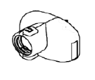
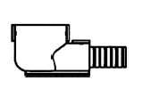
Power supply unit with set of connectors (US, EU, UK, AU) |
X |
USB cable (bootloader, firmware update) |
X |
USB cable (debugging, diagnosis) |
X |
Assembly set M5 Housing GH1208 |
X |
Antenna LTE GNSS DA 3M0 FAKRA-D FAKRA-C FAR |
X |
CANlink mobile 3000 Plug-Kit |
X |
Cable MTII 14pin code1 14open 2m |
X |
2.2.4. Software and Accessories
The software can be downloaded from our Document Library
| Software | Part Number |
|---|---|
Proemion Configurator |
Download-Center |
CANlink mobile 3000 DeviceAnalyzer |
Download-Center |
Remote Service Tool |
Download-Center |
Proemion Firmware Programmer |
Download-Center |
Proemion Machine Companion App |
Google Play |
Proemion Web Portal Setup |
259003021 |
| Material | 33xx, 34xx, 35xx |
|---|---|
PCAN-USB - CAN/USB Interface |
257001041 |
CANlink Connector Kit |
132600031 |
ERGOCRIMP HAND TOOL 539635-1 without die set |
Direct order at supplier |
ERGOCRIMP DIE SET for MICRO Timer and Micro Timer (SWS) 539663-2 |
Direct order at supplier |
MT2 A REC 1.6 Contact SWS Sn (LP) for crimping with hand tool |
Direct order at supplier |
CAN bus termination, D-Sub/D-Sub CAN 120 Ohm |
157000033 |
USB cable, USB-A- Micro USB-A, 1.8 - 2 m |
136000199 |
USB cable, USB-A to Micro-USB-B, 1.6 m |
136000138 |
MT II socket, 14-pin, cod.1, open, 30 cm |
136000188 |
MT II socket, 14-pin, cod.1, open, 2 m |
136000198 |
Adapter Cable CANlink 14p-M12 5p 0,3m |
136200001 |
Adapter Cable CANlink 14p-M12 12p 0,3m |
136200002 |
CLM3 start cable, 6open 2dsub 1pw 2m |
136000197 |
ANT LTE GNSS DA 3M0 FAKRA-D FAKRA-C FA (Shark fin) |
157000109 |
ANT LTE GNSS DA 3M0 FAKRA-D FAKRA-C FAR (Flat Rectangle) |
157000121 |
ASSEMBLY SET M5 HOUSING GH1208 |
141000017 |
Power supply unit, US EU UK AU 24V/0.83A/20W |
257004007 |
2.3. Service and Support
The latest versions of the drivers, software, firmware, and documentation are available in our Document Library.
Do you need help or want to report a bug?
Visit Proemion for more information, or raise a ticket at Support.
2.3.1. Firmware Updates and Support
|
For more information on Firmware Update, see Firmware Update.
3. Safety Information
This chapter contains important information on how to avoid life-threatening situations and injuries and how to prevent product damage.
3.1. Safety Instructions
|
|
|
|
|
|
|
|
|
|
|
|
3.2. CE Notes European Union
The devices described in this device manual may only be used in mobile or stationary systems in which the distance between antennas and persons is at least 20 cm. Furthermore, antennas may only be operated in conjunction with other antennas or transmitters when the correct horizontal distance between them is observed.
|
|
|
Changes or modifications to this device not expressly approved by the manufacturer can void the user’s authority to operate the device under CE rules.
|

3.3. UKCA Notes United Kingdom
The devices described in this device manual may only be used in mobile or stationary systems in which the distance between antennas and persons is at least 20 cm. Furthermore, antennas may only be operated in conjunction with other antennas or transmitters when the correct horizontal distance between them is observed.
|
|
|
Changes or modifications to this device not expressly approved by the manufacturer can void the user’s authority to operate the device under UKCA rules.
|

3.4. FCC Notes USA
The devices described in this device manual may only be used in mobile or stationary systems in which the distance between antennas and persons is at least 20 cm. The antennas must further not be co-located or operated in conjunction with any other antennas or transmitters.
|
|
Changes or modifications to the device not expressly approved by the manufacturer can void the user’s authority to operate the device under FCC rules.
3.5. ISED Notes Canada
English
This product meets the applicable Innovation, Science and Economic Development Canada technical specifications.
This Class B equipment complies with the applicable ISED RSSs Standards and CAN ICES-003 Issue 6. Operation is subject to the following two conditions:
(1) This device may not cause interference, and
(2) This device must accept any interference, including interference that may cause undesired operation of the device.
Radiation Exposure Statement
This device complies with radiation exposure limits prescribed for an uncontrolled environment for fixed and mobile use condition. This equipment should be installed and operated with minimum distance of 20cm between the radiator and the body of the user or nearby persons.
Maximum Cellular Antenna Gain
CANlink mobile 3573, 3577:
The maximum antenna gain including cable and connector loss in a fixed or mobile exposure condition must not exceed +6,5dBi for all applicable WCDMA (2, 5) and LTE (2, 4, 5, 12) Bands.
CANlink mobile 3351, 3353, 3357, 3373, 3377:
The maximum antenna gain including cable and connector loss in a fixed or mobile exposure condition must not exceed +0,6dBi for GSM850/WCDMA2 Bands and +1,5dBi for GSM1900/WCDMA5 Bands.
Changes or modifications to this device not expressly approved by the manufacturer can void the user’s authority to operate the device under ISED rules.
|
Français
Ce produit est conforme aux spécifications techniques applicables d’Innovation, Sciences et Développement Économique Canada.
Cet équipement de classe B est conforme aux normes ISDE RSS applicables et à la norme CAN ICES-003, Numéro 6. Son fonctionnement est soumis aux deux conditions suivantes:
(1) Cet appareil ne doit pas provoquer d’interférences et
(2) Cet appareil doit accepter toute interférence, y compris les interférences qui peuvent provoquer un fonctionnement indésirable de l’appareil.
Déclaration d’exposition aux rayonnements
Cet appareil est conforme aux limites d’exposition aux rayonnements prescrites pour un environnement non contrôlé dans des conditions d’utilisation fixe et mobile. Cet équipement doit être installé et utilisé à une distance minimale de 20 cm entre le radiateur et le corps de l’utilisateur ou des personnes à proximité.
Gain d’antenne cellulaire maximal
CANlink mobile 3573, 3577:
Le gain d’antenne maximal, y compris les pertes du câble et du connecteur dans des conditions d’exposition fixe ou mobile, ne doit pas dépasser +6,5 dBi pour toutes les bandes WCDMA (2, 5) et LTE (2, 4, 5, 12).
CANlink mobile 3351, 3353, 3357, 3373, 3377:
Le gain d’antenne maximal, y compris les pertes du câble et du connecteur dans des conditions d’exposition fixe ou mobile, ne doit pas dépasser +0,6 dBi pour les bandes GSM850/WCDMA2 and +1,5 dBi pour les bandes GSM1900/WCDMA5.
Les changements ou modifications de cet appareil non expressément approuvés par le fabricant peuvent annuler le droit de l’utilisateur à utiliser l’appareil selon la réglementation ISDE.
|
3.6. Warranty and Liability
Proemion assumes no liability for defects caused by normal wear, external influences and incorrect installation, operation or maintenance. This also applies if the customer or a third party modifies the devices, any accessories, or the software without permission from Proemion.
4. Functionality and Features
This chapter contains information on device functionality and features. It provides details of the operating modes, connectors, cables, pin assignments, interfaces and indicator elements.
4.1. Functions
| Function | 3311 | 3317 | 3333 | 3337 | 3351 | 3355 | 3357 | 3373 | 3377 | 3477 | 3577 |
|---|---|---|---|---|---|---|---|---|---|---|---|
CAN-CAN Bluetooth / WLAN bridge |
No |
No |
Yes |
Yes |
No |
No |
No |
Yes |
Yes |
Yes |
Yes |
CAN-Bluetooth/WLAN interface |
No |
No |
Yes |
Yes |
No |
No |
No |
Yes |
Yes |
Yes |
Yes |
Battery |
No |
Yes |
No |
Yes |
No |
Yes |
Yes |
No |
Yes |
Yes |
Yes |
Antenna (internal / external) |
int. |
int. |
int. |
int. |
ext. |
ext. |
ext. |
ext. |
ext. |
ext. |
ext. |
Mobile radio (3G/4G) |
3G |
3G |
3G |
3G |
3G |
3G |
3G |
3G |
3G |
4G EU |
4G US |
RealTime mode |
Yes |
Yes |
Yes |
Yes |
Yes |
Yes |
Yes |
Yes |
Yes |
Yes |
Yes |
Logging mode |
Yes |
Yes |
Yes |
Yes |
Yes |
Yes |
Yes |
Yes |
Yes |
Yes |
Yes |
Input/output functions |
Yes |
Yes |
Yes |
Yes |
Yes |
Yes |
Yes |
Yes |
Yes |
Yes |
Yes |
Acceleration sensor |
Yes |
Yes |
Yes |
Yes |
Yes |
Yes |
Yes |
Yes |
Yes |
Yes |
Yes |
Gyro sensor |
Yes |
Yes |
Yes |
Yes |
Yes |
Yes |
Yes |
Yes |
Yes |
Yes |
Yes |
CAN interfaces |
1 |
2 |
2 |
2 |
1 |
1 |
2 |
2 |
2 |
2 |
2 |
GNSS |
Yes |
Yes |
Yes |
Yes |
Yes |
Yes |
Yes |
Yes |
Yes |
Yes |
Yes |
eSIM card |
Yes |
Yes |
Yes |
Yes |
Yes |
Yes |
Yes |
Yes |
Yes |
Yes |
Yes |
4.1.1. CAN-CAN Bluetooth/WLAN Bridge
In operation as a CAN-CAN Bluetooth/WLAN bridge (types 3333, 3337, 3373, 3377, 3477, 3577), CAN data is transmitted wirelessly between two CANlink mobile or CANlink wireless devices via a Bluetooth or WLAN connection. The CAN-CAN Bluetooth/WLAN bridge acts as a substitute for CAN cables, e.g. in cable carriers or with remote-control units.
4.1.2. CAN-Bluetooth/WLAN Interface
The device is designed for wireless operation via Bluetooth or WLAN interface.
CAN-Bluetooth interface
In operation as a CAN Bluetooth interface (types 3333, 3337, 3373, 3377, 3477, 3577), CAN data is transmitted wirelessly and bidirectionally to other Bluetooth-capable devices supported by the Proemion byte command protocol, e.g. CANlink wireless, CANlink Bluetooth, PCs, smartphones or tablet PCs.
The device supports Bluetooth Classic (2.1+ EDR). Bluetooth Low Energy (BLE) can be made available on request.
CAN-WLAN interface
In operation via the CAN-WLAN interface (types 3333, 3337, 3373, 3377, 3477, 3577), CAN data is transmitted wirelessly and bidirectionally to other WLAN-capable devices supported by the Proemion byte command protocol, e.g. CANlink wireless, PCs, smartphones or tablet PCs.
The CAN-WLAN interface features two operating modes: infrastructure mode and mini access point mode. In infrastructure mode, data transmission takes place via one or more access points. In mini access point mode, the CANlink mobile 3000 additionally provides a WLAN access point function.
WLAN Encryption
| Name | Authentication | Data Protection |
|---|---|---|
None |
No |
No |
WEP64 |
Yes |
according to WEP64 |
WEP128 |
Yes |
according to WEP128 |
WPA/WPA2 Mixed Mode |
Yes |
according to WPA or WPA2 |
PEAP |
Yes |
via RADIUS server |
WLAN Frequencies and Channels
The device’s WLAN interface features automatic domain recognition and supports the following regulatory domains: WORLD, ETSI, FCC. If neither ETSI nor FCC are recognized, the radio module uses WORLD as a standard.
| Name | Band | TX Channel |
|---|---|---|
World |
2.4 Ghz |
1, 2, 3, 4, 5, 6, 7, 8, 9, 10, 11 |
U-NII-1 |
36, 40, 44, 48 |
|
U-NII-2 |
52, 56, 60, 64 |
|
U-NII-2e |
100, 104, 108, 112, 116, 132, 136, 140 |
|
U-NII-3 |
- |
|
ETSI |
2.4 GHz |
1, 2, 3, 4, 5, 6, 7, 8, 9, 10, 11, 12, 13 |
U-NII-1 |
36, 40, 44, 48 |
|
U-NII-2 |
52, 56, 60, 64 |
|
U-NII-2e |
100, 104, 108, 112, 116, 120, 124, 128, 132, 136, 140 |
|
U-NII-3 |
149, 153, 157, 161, 165 |
|
FCC |
2.4 GHz |
1, 2, 3, 4, 5, 6, 7, 8, 9, 10, 11 |
U-NII-1 |
36, 40, 44, 48 |
|
U-NII-2 |
52, 56, 60, 64 |
|
U-NII-2e |
100, 104, 108, 112, 116, 132, 136, 140 |
|
U-NII-3 |
149, 153, 157, 161, 165 |
|
4.1.3. Battery
Some device types feature an integrated battery (lithium-polymer).
The integrated battery allows it to send logged CAN and position data via the cellular radio interface even if the power supply from the main plug connector is interrupted. The device is not designed for permanent battery operation.
On delivery, the integrated battery is charged by approx. 30%. Before you use the device, charge the battery fully. See Charging the Battery.
A fully charged battery can back up a power failure of approx. 1.5 hours (@ 20°C battery temperature), ensuring active operation of the device.
The following examples provide an overview of the battery runtimes in various application cases.
Example 1:
The rechargeable battery integrated is charged to 100% and the device is permanently switched on and online. The device transmits one file per minute. The battery runtime is approx. 2 hours.
Example 2:
The integrated battery is charged by 100% and the device is permanently in Sleep mode. The device switches on cyclically every 24 hours and is online for 5 minutes to transmit the current position and certain internal device parameters. Then the device automatically switches back to sleep mode. The battery runtime is approx. 14 days.
Example 3:
The integrated battery is charged by 100% and the device is permanently in Sleep mode. The device goes online only once, triggered by the acceleration sensor, and transmits the current position (theft monitoring without external power supply). The battery runtime (operational readiness) is 70 days.
The values stated in the examples can deviate depending on the use purpose and setup conditions (@ 20°C battery temperature).
|
|
4.1.4. Mobile Radio Interface
The device is equipped with a mobile radio interface for mobile data transmission.
Depending on the type, the device supports the 3G or 4G mobile network. To achieve greater network coverage, all types feature a fallback function to a different mobile network. Types 3333, 3337, 3351, 3373 and 3477 switch to the 2G mobile network, and type 3577 switches to the 3G mobile network.
The device detects the mobile network with the best transmission speed and automatically changes to the corresponding mobile network.
You can use the mobile interface to transmit data bidirectionally via the mobile network.
4.1.5. RealTime Mode
In RealTime mode, CAN messages are transmitted bidirectionally.
You can use the CAN interfaces on the device to transmit process data, such as machine parameters, during ongoing operations via Bluetooth/WLAN, the mobile network and DataPlatform. Depending on the device features, you can transmit data from the GNSS receiver and the input/output functions and pass them on via the CAN bus.
Alternatively, the device can use a WLAN or Bluetooth connection to receive data from an external receiver, e.g., the CANlink wireless, and transmit it to the local CAN interfaces.
Data is transmitted constantly and can be evaluated in close to RealTime. This function requires a permanent link between the device and the user software or DataPlatform.
4.1.6. Logging Mode
When Logging mode is activated, the device records CAN messages, GNSS data and internal variables, such as the values of the acceleration or gyro sensors. All the recorded data is saved in an internal, nonvolatile memory and sent to the DataPlatform.
The device can be used to record process data, such as machine parameters, during ongoing operation via CAN interfaces. Depending on the device features, you can process data from the GNSS receiver and the input/output functions, send and log them via the CAN bus.
4.1.7. Input/Output Functions
The device is equipped with an additional input/output functions (3 analog inputs, 1 digital output). You can use the input function for instance to log status information from devices or machines as well as to directly determine and monitor switch and key states. The data determined from the input/output functions can be visualized or forwarded via the CAN bus.
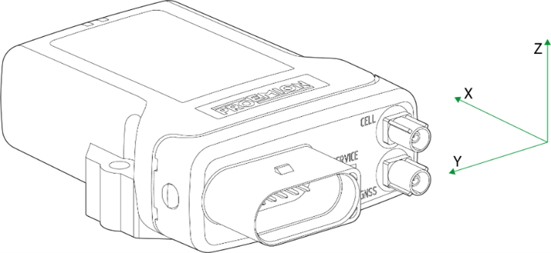
4.1.8. Acceleration Sensor
The acceleration sensor registers and evaluates accelerations in the directions of the X, Y, and Z axes, and sends them via the CAN bus.

| Sensor is not calibrated. |
4.1.9. Gyro Sensor
The 3-axis gyro sensor registers and evaluates the angle speeds in the X, Y, and Z axes and sends them to the CAN bus.
| Sensor is not calibrated. |
4.1.10. GNSS-Global Navigation Satellite System
The device is equipped with a GNSS receiver. You can send the position data determined by the GNSS receiver via the CAN bus or the mobile radio network. The receiver can process signals from GPS, GLONASS and BeiDou satellites. It can process data from two navigation systems simultaneously. This increases the accuracy.
4.1.11. eSIM card
All device variants are equipped with an integrated eSIM card. On delivery, the eSIM card already has an eSIM profile with all the necessary communication settings.
|
|
4.2. Connectors
The device is equipped with the following connectors:
-
1 main plug connector (14-pin): CAN1 / CAN2 / VCC / GND / AIN1-3 / DOUT / CAN3
-
1 GNSS antenna port, FAKRA, C-coded in blue (types 3351, 3373, 3377, 3477, 3577)
-
1 mobile radio antenna port, FAKRA, D-coded violet (types 3351, 3373, 3377, 3477, 3577)
-
1 micro-USB port, type AB
|
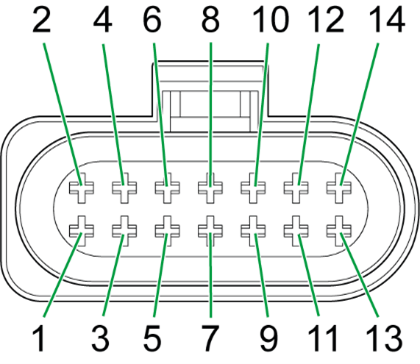
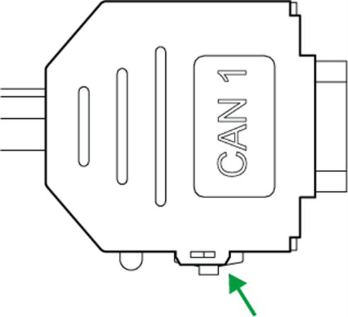
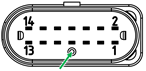
4.2.1. Main Plug Connector
Use the main plug connector to connect the device to the CAN bus and supply it with power. The I/O signals are integrated in the plug connector.
|
|
|
|
Pin layout of all CANlink mobile 3000 types
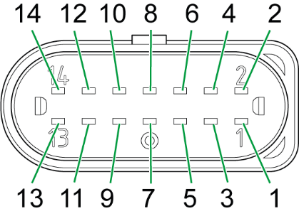
| Pin | Designation | Description |
|---|---|---|
1 |
Terminal 30 / VCC |
Power supply |
2 |
Factory setting 1 |
Input |
3 |
Terminal 31 / ground |
Power supply |
4 |
Analog input 1 |
I/O input |
5 |
Analog input 2 |
I/O input |
6 |
Analog input 3 |
I/O input |
7 |
Digital output |
I/O output |
8 |
Terminal 15 |
Input (ignition signal) |
9 |
Factory setting 2 |
Input |
10 |
CAN2-GND |
- |
11 |
CAN2-High |
CAN, bidirectional |
12 |
CAN2-Low |
CAN, bidirectional |
13 |
CAN1-High |
CAN, bidirectional |
14 |
CAN1-Low |
CAN, bidirectional |
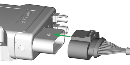
Connect main plug connector
Carefully connect the cable with the main plug connector. When connecting the plug, there must be a clear audible click. Then the lock is correctly engaged.
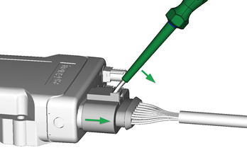
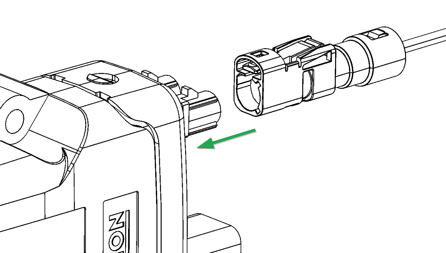
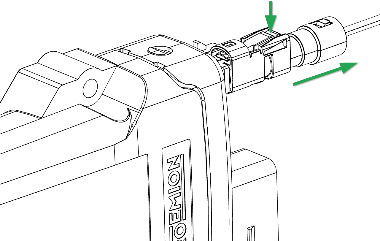
Disconnect main plug connector
Use an appropriate flat-blade screwdriver to release the lock. To do this, insert the screwdriver into the tab from above, then gently lever it down and back. At the same time, pull the plug slightly backwards by hand. If you can hear a click, the lock has been released and the connector can be removed.
|
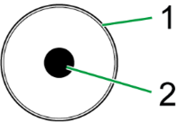
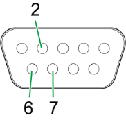
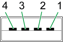
4.2.2. GNSS Antenna Connector
The GNSS antenna connector is used to connect the device with an active antenna to receive signals from GNSS satellites. Refer to the following overview for the pin assignment:
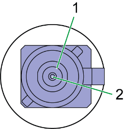
| Pin | Designation | Description |
|---|---|---|
1 |
Ground |
Signal ground /shielding |
2 |
Signal |
GNSS signal / supply voltage 3.3 V |
The GNSS antenna port is supplied with a voltage of approx. 3.3 V and can supply active antennas with a maximum of 40 mA of power. The port is short-circuit-proof against Ground and detects an antenna is present from a current drawn greater than approx. 2 mA.
|
|
|
For connecting and disconnecting the antenna, please refer to Connect antenna cable and Disconnect antenna cable.
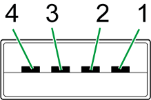
4.2.3. Mobile radio antenna connector
Use the mobile radio antenna connector to connect the device with an antenna to receive mobile radio signals. See the following overview for the pin assignment:
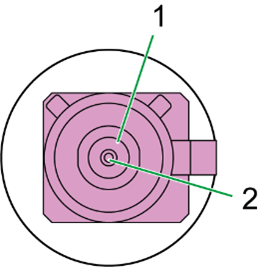
| Pin | Designation | Description |
|---|---|---|
1 |
Ground |
Signal ground /shielding |
2 |
Signal |
Mobile Radio |
The port is short-circuit-proof against Ground and detects the connection of an antenna in case that it has an integrated diagnosis resistance (10 kOhm).
|
|
|
Connect antenna cable
Carefully connect the antenna cable with the coded antenna connector. Make sure that the coding within the socket is matching the coding of the connector. When connecting the plug, there must be a clear audible click. Then the lock is correctly engaged.
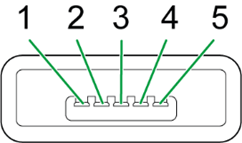
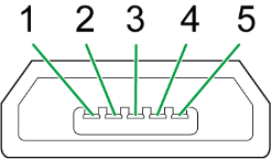
4.2.4. Micro-USB Port
Use the micro-USB port to connect the device to a PC. The micro-USB port is used for diagnoses as well as for bootloader and firmware updates.
For instructions on how to perform diagnoses, see Diagnosis via micro-USB port.
For instructions on how to update the bootloader and firmware, see Firmware update.
See the following overview for the pin assignment:
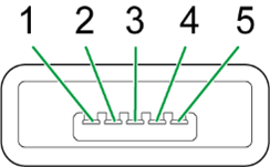
| Pin | Designation | Description |
|---|---|---|
1 |
VBUS |
Input |
2 |
D- |
Bidirectional |
3 |
D+ |
Bidirectional |
4 |
ID |
Input (0=boot mode, 1/open=USB device) |
5 |
Ground |
USB power supply / reference ground |
|
|
|
|
|
4.3. Indicator Elements
Two LEDs are installed on the front of the device to indicate functions and status.
|
The following tables show possible LED statuses:
4.3.1. ON LED
The ON LED indicates the power supply status.
| Color | Status | Meaning |
|---|---|---|
- |
Off |
Device switched off or in sleep mode |
Green |
On |
Device switched on, terminal 30 voltage in permitted range |
Red |
On |
Device switched on, terminal 30 voltage outside permitted range |
Green |
Flashing |
Device in diagnosis or update mode |
Orange |
On |
Device is in device reset mode. See also LEDs during certain operating modes |
4.3.2. STATUS LED
The STATUS LED indicates the operating status of the active connections. The various colors reflect the respective priority, from 6 (low) to 1 (high).
If several modes are active simultaneously, the STATUS LED always indicates the status with the highest priority (smallest number).
| Color | Status | Connection | Priority | Meaning |
|---|---|---|---|---|
- |
Off |
- |
- |
LED On is also off, the device is switched off. |
Green |
On |
Various |
- |
No Error. Device is connected to the DataPlatform |
Blue |
On |
Mobile radio internet |
1 |
Not connected to the DataPlatform. |
Orange |
On |
CAN 1 |
2 |
Error on CAN 1 interface. |
Red |
On |
CAN 2 |
3 |
Error on CAN 2 interface. |
White |
On |
CAN 3 |
4 |
Error on CAN 3 interface. |
Magenta |
On |
GNSS |
5 |
No position / antenna recognized. |
- |
Off |
WLAN Bluetooth |
6 |
Not connected to any network / device. |
|
4.3.3. LEDs during certain operating modes
The LEDs indicate certain active operating modes and processes.
|
LED |
Status |
Meaning |
On |
|
Configuration update in progress via the CAN interface. |
On |
|
Active file transfer in Logging mode. A configured CAN message is received (flashes orange) and sent to the DataPlatform (flashes blue). |
On |
|
Active data transmission in RealTime mode. |
On |
|
Device initializing after switching on. |
On |
|
Configuration update in progress via the DataPlatform. |
On |
|
Remote firmware update in progress via the DataPlatform. |
On |
|
Device reset via slide switch on the D-sub connector CAN1 (Only CLM 3000). |
On |
|
Reset ( |
On |
|
Transmission of the GNSS position and the keep-alive message. Display varies depending on configured polling interval. |


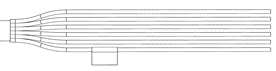
4.4. Cables
|
4.4.1. Start Cable / Main Plug Connector CANlink mobile 3000
The cable CLM3 start cable 6 open, 2 D-Sub, 1 pw, 2 m (part number 136000197) must be used for the CANlink mobile 3000 variants and is equipped with the following connectors and open individual wires:
-
1 micro timer II socket,14-pin, female
-
2 D-sub, 9-pin, female (CAN1 and CAN2)
-
1 power connector
| Pin | Designation | Color | Description |
|---|---|---|---|
1 |
Terminal 30 / VCC |
White |
Power supply (steady plus vehicle battery) |
2 |
Factory setting 1 |
Brown |
Input |
3 |
Terminal 31 / ground |
Green |
Power supply |
4 |
Analog input 1 |
Yellow |
I/O input |
5 |
Analog input 2 |
Gray |
I/O input |
6 |
Analog input 3 |
Pink |
I/O input |
7 |
Digital output |
Blue |
I/O output |
8 |
Terminal 15 |
Red |
Input (ignition signal) |
9 |
Factory setting 2 |
Black |
Input |
10 |
CAN2-GND |
Violet |
- |
11 |
CAN2-High |
Gray-pink |
CAN, bidirectional |
12 |
CAN2-Low |
Red-blue |
CAN, bidirectional |
13 |
CAN1-High |
White-green |
CAN, bidirectional |
14 |
CAN1-Low |
Brown-green |
CAN, bidirectional |
|
| Designation | Color | Description |
|---|---|---|
Terminal 31 / ground |
Green |
Power supply |
Analog input 1 |
Yellow |
I/O input |
Analog input 2 |
Gray |
I/O input |
Analog input 3 |
Pink |
I/O input |
Digital output |
Blue |
I/O output |
Terminal 15 |
Red |
Input (ignition signal) |
| Pin | Designation | Color | Description |
|---|---|---|---|
1 |
Terminal 31 / ground |
Green |
Power supply |
2 |
Terminal 30 / VCC |
White |
Power supply |
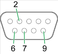
| Pin | Designation | Color | Description |
|---|---|---|---|
1 |
not assigned |
- |
- |
2 |
CAN1-Low |
Brown-green |
CAN, bidirectional |
4 |
not assigned |
- |
- |
5 |
not assigned |
- |
- |
6 |
Terminal 31 / ground |
Green |
- |
7 |
CAN1-High |
White-green |
CAN, bidirectional |
8 |
not assigned |
- |
- |
9 |
Terminal 30 / VCC |
White |
Power supply |
The D-Sub connector (CAN1) connection is also equipped with a slide switch to complete a reset to the factory settings.
|
| Pin | Designation | Color | Description |
|---|---|---|---|
1 |
not assigned |
- |
- |
2 |
CAN2-Low |
Red-blue |
CAN, bidirectional |
3 |
not assigned |
- |
- |
4 |
not assigned |
- |
- |
5 |
not assigned |
- |
- |
6 |
CAN2-GND |
Violet |
- |
7 |
CAN2-High |
Gray-pink |
CAN, bidirectional |
8 |
not assigned |
- |
- |
9 |
not assigned |
- |
- |
4.4.2. USB Connector Cable - Firmware Update
The USB cable, USB A-micro USB A, 1.8-2 m (part number 136000199) is intended for firmware or bootloader updates and has the following connectors:
-
1 micro-USB-A, male
-
1 USB-A, male
| Pin | Designation | Description |
|---|---|---|
1 |
VBUS |
USB power supply |
2 |
D- |
Bidirectional |
3 |
D+ |
Bidirectional |
4 |
ID |
Ground, output |
5 |
Ground |
USB power supply |
| Pin | Designation | Description |
|---|---|---|
1 |
VBUS |
USB power supply |
2 |
D- |
Bidirectional |
3 |
D+ |
Bidirectional |
4 |
Ground |
USB power supply |
|
|
4.4.3. USB Connector Cable - Diagnostic
The USB cable, USB-A on micro-USB-B, 1.6 m (part number 136000138) is intended for debugging and for diagnosis of the device. It has the following connectors:
-
1 micro-USB-B, male
-
1 USB-A, male
| Pin | Designation | Description |
|---|---|---|
1 |
VBUS |
USB power supply |
2 |
D- |
Bidirectional |
3 |
D+ |
Bidirectional |
4 |
ID |
Output (ID is undefined) |
5 |
Ground |
USB power supply |
| Pin | Designation | Description |
|---|---|---|
1 |
VBUS |
USB power supply |
2 |
D- |
Bidirectional |
3 |
D+ |
Bidirectional |
4 |
Ground |
USB power supply |
4.4.4. Custom Cable for Main Plug
When creating a customized cable harness for the system integration of the CANlink mobile 3000, some important recommendation for the setup of the main plug connector and cable must be considered. It is recommended to use the connector components from the Software and accessories list to create a custom cable harness.
|
|

-
For the cable assembly it is essential that the instructions from the handling manual of the connector supplier are followed. Especially the main sealing, wire sealing and dummy plugs must be installed in the right manner. Refer to Automotive Connectors.

-
Use only the recommended tooling for machine processing. Refer to Go to Download Center > 01_Proemion Devices > 01_CANlink mobile 3600 > 01_Documentation > CANlink Connector Kit.
-
It is recommended to use tinned contacts. This corresponds the material of the pins

-
Use the wire sealing which fits to the outer diameter of the used wires

-
Cover the unused contact sockets with dummy plugs to protect the connection from dust and humidity
4.4.5. Cable Management
|
-
Protect the connector and the cable with sufficient covers and cable tubing. Please refer to the Schlemmer for more information.
The following part numbers are recommended for the protective cover:
| Symbol | Part Numbers |
|---|---|
|
7807174 |
|
7807207 |
|
7807624 |
4.4.6. Adapter Cable for Retrofit
The Adapter Cable CANlink 14p-M12 5p 0,3m (part number 136200001) and Adapter Cable CANlink 14p-M12 12p 0,3m (part number 136200002) is intended for CANlink mobile 3000 retrofits at machines which are already equipped with a CANlink mobile 5000. With this adapter cable there is no need to modify the existing cable harness of the machine when the existing CANlink mobile 5000 is to be replaced by the CANlink mobile 3000 device.
| Variant installed at Machine | Part number of required cable for retrofit |
|---|---|
CANlink mobile 5201 |
136200001 |
CANlink mobile 5301 |
136200001 |
CANlink mobile 5303 |
136200002 |
CANlink mobile 5320 |
136200002 |
For detailed drawings of the adapter cables, please refer to Adapter Cable CANlink 14p-M12 5p 0,3m (136200001) and Adapter Cable CANlink 14p-M12 12p 0,3m (136200002) in Technical Drawings.
ting Started= Get
This chapter describes the first steps required for deploying the device. Furthermore, it contains useful information on how to connect, configure, and mount the device.
4.5. Installing Software
Use the Proemion Configurator software to configure the device.
You can evaluate the data with the DataPlatform or Remote Service Tool.
Use the Proemion Firmware Programmer software for firmware updates.
|
The software can be downloaded from our Download Center at the Document Library |
| Software | Path on Download Center |
|---|---|
Proemion Configurator |
03_Proemion Tools Software\01_Software\01_Proemion Configurator |
CANlink mobile 3000 DeviceAnalyzer |
03_Proemion Tools Software\01_Software\08_CANlink mobile 3000 DeviceAnalyzer |
Remote Service Tool |
03_Proemion Tools Software\01_Software\04_Remote Service Tool |
Proemion Firmware Programmer |
03_Proemion Tools Software\01_Software\02_Proemion Firmware Programmer |
Drivers |
05_Utilities\06_USB Drivers |
Proemion Machine Companion App |
Execute the relevant application file (setup.exe, install.bat or similar) and follow the instructions on the screen to install the software on your PC.
4.6. Connecting the Device
|
|
|
|
If you have any questions or anything is unclear, please contact our support before getting started. See Service and Support. |
4.6.1. Power Supply
The main plug connector supplies the device with power. If you use the power supply unit from the kit, make sure you use the country adapter for your country.
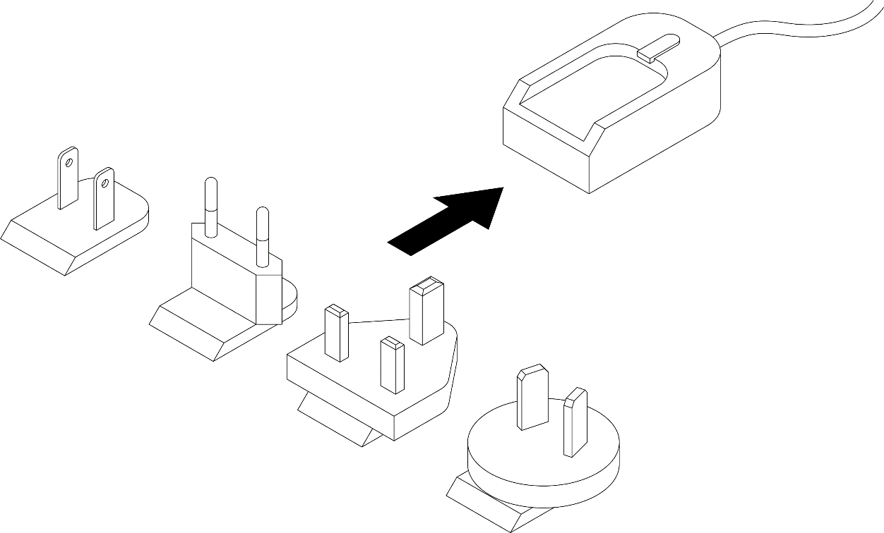
4.6.2. Charging the Battery
Before you use the device for the first time, fully charge the integrated battery using main plug connector cable supplied. See Start Cable for Main Plug Connector.
|
|
|
4.6.3. CAN
Connect the device interfaces to the CAN bus whose data you want to visualize. For test purposes, connect the device to a PC using a communication gateway (e.g. PCAN-USB - CAN/USB Interface).
The CAN connection terminal CAN-High and CAN-Low signals must match the signals of the connector on the device. You can connect ground of the power supply connector with CAN1-GND or CAN3-GND because the CAN1 and CAN3 interface has no galvanic isolation. The CAN2 interface is galvanically isolated from the rest of the circuit and must not be connected with supply-GND.
The following table provides an overview of some CAN baud rates in relation to the bus length:
| CAN baudrate | Maximum bus length |
|---|---|
1 Mbit/s |
25 m |
800 kbit/s |
50 m |
500 kbit/s |
100 m |
250 kbit/s |
250 m |
125 kbit/s |
500 m |
50 kbit/s |
1000 m |
4.6.4. CAN Bus Termination
In any bus system, signal reflections at the end of a wire or cable can cause interference which can in turn cause transmission errors. To minimize the reflections, place a termination resistor at each end of transmission lines. The terminating resistance between CAN-High and CAN-Low must match the characteristic impedance of the transmission lines.
In CAN bus networks, normally unshielded, twisted cable pairs are used for signal transmission. The characteristic impedance of the transmission lines is around 120 Ohm. So, the termination resistor between CAN-High and CAN-Low must be rated 120 Ohm.
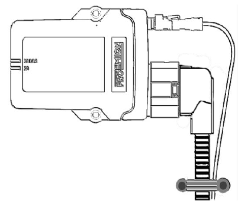
4.6.5. Mobile Radio and GNSS Antenna
Some types of the device (types 3351, 3373, 3377, 3477, 3577, 3355, 3357) are equipped with external antenna ports for mobile radio and GNSS signals.
The antenna ANT LTE GNSS DA 3M0 FAKRA-D FAKRA-C FAR (part number 157000121) features a port for mobile radio signals (FAKRA-D - violet) and a port for GNSS signals (FAKRA-C - blue).
|
|
|
MOBILE RADIO CONNECTOR
Connect the antenna’s FAKRA-D plug (violet) to the device’s FAKRA-D port (violet).
|
GNSS CONNECTOR
Connect the antenna’s FAKRA-C plug (blue) to the device’s FAKRA-C port (blue)
|
|
4.6.6. Switching the Device On/Off
The device does not have an on/off switch.
The device can be powered on by each of the following conditions:
- Terminal 15 level is high
- CAN message is present at CAN1 (wakeup via CAN2 is not possible)
- Detection of a specific Acceleration Sensor Wake-up Force
- Cyclic wakeup time is elapsed
The device can be set to sleep mode by the following conditions: tbd (firmware/software implementation is not defined yet)
Permanent disconnection from the power supply is only permissible if the device has been set to sleep mode before.
For further details regarding the different power management functions, please refer to Power Management.
|
|
4.7. Activation
The CANlink® mobile 3000 is equipped with an integrated eSIM card.
Upon delivery, the eSIM card already has an eSIM profile with all the necessary communication settings.
Before you can use the device, it must be activated via the DataPortal.
|
The user that wants to activate the device needs at least the permission set (Machine:Admin) and the feature switch (Machine Lifecycle) must be enabled for the user’s organization unit. If this should not be the case, please get in contact with the administrator of your organization or our support team. See Service and Support. For more information, see the chapters Permissions > Machines Service and Feature Switch in the DataPortal User Manual. |
-
Log in to the DataPortal.
-
Go to Administration > Overview.
-
Select the Machines tab.
-
Select Provision Machine button and follow the instruction in the chapters Provisioning and GoLive in the DataPortal User Manual for activating the device.
4.8. Configuring the Device
The device is delivered with a basic configuration. Customize the configuration to your purposes by defining the CAN messages to be logged.
You load new configurations to the device via CAN interface or the DataPortal. Configuration is described below using the CAN interface. For more detailed information on configuration using the DataPlatform, see chapters Configuration update and Safe Remote Updates Guideline.
4.8.1. Connecting the Device to the PC
To configure the device with a PC, you must connect it with the PC. In this example, using a PCAN-USB - CAN/USB Interface from the Launch Kit.
-
Connect the PCAN-USB - CAN/USB Interface to a PC using the cable USB connection cable, USB-A to USB-B, 2 m.
-
Place a CAN bus termination on the D-Sub connector of the PCAN-USB - CAN/USB Interface.
-
Use the cable Start cable for main plug connector with the CAN1 or CAN2 plug to connect the CANlink mobile to the CAN-bus termination of the PCAN-USB - CAN/USB Interface.
-
Use the cable Start cable for main plug connector and the power supply unit from the launchkit to connect the CANlink mobile to the power grid.
✓ The ON LED lights up in constant green.
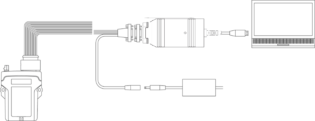
Image of PCAN-USB copied from PCAN-USB User Manual.
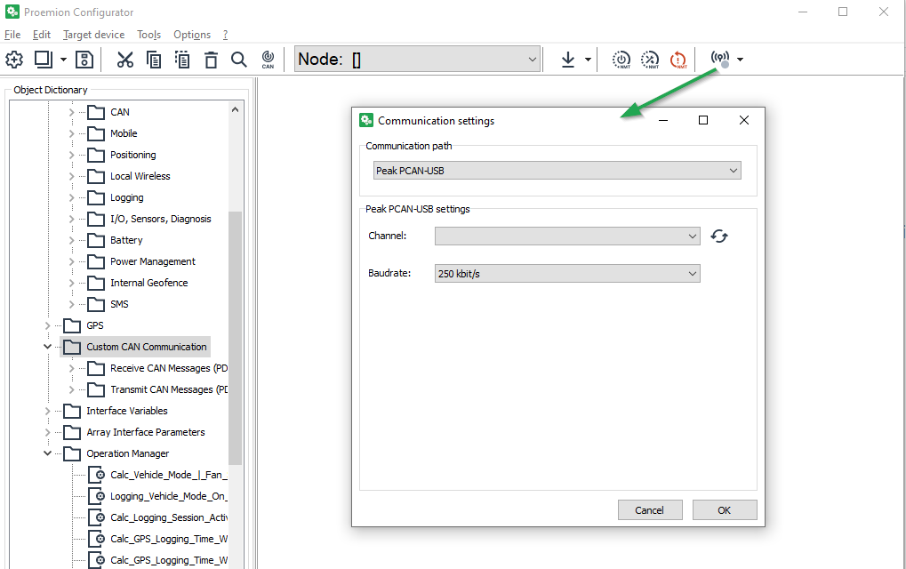
4.8.2. Making Communications Settings
Before you can start using the device, you must define the communication settings once.
|
-
Connect the device to a PC. See Connecting the Device to the PC.
-
Start the Proemion Configurator software.
-
To open the COMMUNICATIONS SETTINGS, in the menu bar click the
 Communication Gateway icon.
✓ The window COMMUNICATION SETTINGS opens.
-
In the Communication path, select PEAK PCAN-USB as the device.
-
In the PEAK PCAN-USB settings, select Baudrate: 250 kbit/s.
✓ You have completed the communication settings.
4.8.3. Node Scan
Perform a node scan to check the connection.
-
Connect the device to a PC. See Connecting the Device to the PC.
-
Start the Proemion Configurator software.
-
Click on TOOLS > NODE SCAN in the menu.
Alternatively, you can click on the button in the toolbar.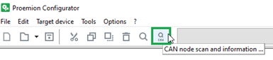
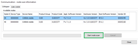
✓ The COMMUNICATION-NODE SCAN INFORMATION window opens.
-
Click on the START NODE SCAN button.
✓ The CAN devices connected are displayed with their CAN open Node-IDs, product codes, and information on hardware and software versions.
-
Select the device you want to configure.
-
Click on the CLOSE button.
✓ The Node-ID and the designation of the selected device are shown in the toolbar.

4.8.4. Customizing the demo configuration File
-
Connect the device to a PC. See Connecting the Device to the PC.
-
Start the Proemion Configurator software.
-
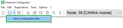
Click on the arrow in the toolbar and select DEMO CONFIGURATION FILES.
✓ The OPEN DOD FILE window is shown.
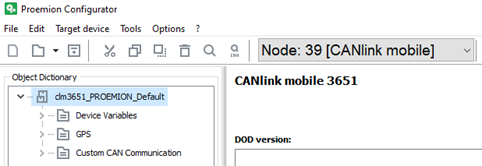
-
Navigate to the correct folder for your device (in this example CANLINK mobile 3351) and open one of the files with the extension *.DOD.
✓ The selected demo configuration file is loaded.
-
Click on FILE > SAVE AS… in the menu.
-
Save the file under a different name to avoid overwriting the original file.
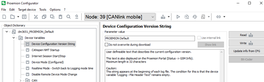
You can enter a designation for the configuration in the DEVICE CONFIGURATION VERSION STRING object of the DEVICE VARIABLES. This text is displayed as a DOD version in the DataPortal under Communication Unit Details and in the configuration version history.
-
Use an unequivocal designation for every configuration. Differentiate between various versions of a configuration by adding a version number.
-
-
Adjust the configuration file to your requirements. See Proemion Configurator.
-
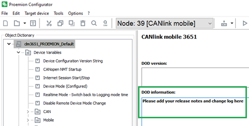
Customize the DEVICE CONFIGURATION VERSION STRING
-
Enter notes on the adaptations completed in the DOD INFORMATION field.
|
|
4.8.5. Loading the Configuration to the Device via CAN Interface
After you have created your own configuration file, load the configuration to the device.
-
Connect the device to a PC. See Connecting the Device to the PC.
-
Start the Proemion Configurator software.
-
Define the communication settings for the PCAN-USB - CAN/USB Interface device. See Making Communications Settings.
-
Complete a Node Scan and select the CAN node of the corresponding device.
-
Choose FILE > OPEN… from the menu.
-
Open the desired configuration file.
-
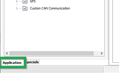
Select the APPLICATION tab.
-
Click on the DOWNLOAD ALL ENTRIES button in the toolbar.
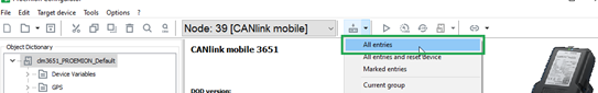
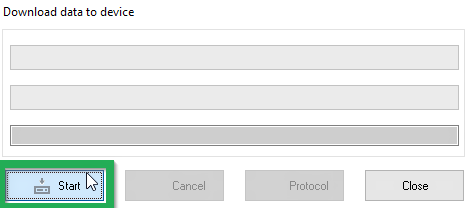
✓ The DOWNLOAD DATA TO DEVICE window is shown.
-
Click on the START button to start the download to the device.
-
Wait until the download is completed.
NOTICE
Loss of function or configuration.
Disconnection from the power supply during the update process can lead to a loss of the function or the configuration.
* Do not disconnect the power supply during updating.✓ The configuration has now been installed on the device.
-
Click on the RESET CAN NODE button.
-
If you have changed the CAN baud rate (DEVICE CAN BAUD RATE) in the configuration, check whether the configuration has been correctly adopted.
-
Change the CAN baud rate of the PCAN-USB - CAN/USB Interface. See Making Communications Settings.
-
Perform a Node Scan to check the connection.
✓ The ON LED lights up in constant green.
✓ The STATUS LED flashes green, then lights up in constant green.
|
4.9. CAN-CAN-Bluetooth/WLAN Bridge
Operation as a CAN-CAN-Bluetooth bridge enables wireless transfer of CAN data between two CAN bus systems. In this case, two CANlink mobile devices or one CANlink mobile 3000 in combination with one CANlink wireless replace the CAN cable.
|
After switching on, a connection is automatically established between a configured master and a slave device. Data is exchanged bidirectionally as soon as the connection between the two devices has been established.
|
For more information on the CAN-CAN Bluetooth bridge and CAN-WLAN bridge operating modes, refer to the CANlink wireless Series 3000 Manual on the Download Center. |
4.10. CAN-Bluetooth Interface
Operation as a CAN-Bluetooth interface enables wireless transmission of CAN data to other Bluetooth-capable devices, such as the CANlink wireless, CANlink Bluetooth, PCs, smartphones, or tablets, on which the CAN data can then be recorded and evaluated. The exchange of data is bidirectional with the support of the Proemion Byte Command Protocol transmission protocol as soon as the software has established a connection to the device.
We recommend using the Remote Service Tool software for visualization and evaluation of the data received. Alternatively, you can use software you program yourself.
|
For more information on the CAN-Bluetooth interface operating mode, refer to the CANlink wireless Series 3000 Manual and Byte Command Manual manuals on the Download Center. |
4.11. CAN-WLAN Interface
Operation as a CAN-WLAN interface enables wireless transmission of CAN data to other WLAN-capable devices such as the CANlink wireless, PCs, smartphones or tablets. The CAN data is then recorded and evaluated on these devices. The data transfer is bidirectional with the support of the Proemion Byte Command Protocol as soon as the software has created a connection to the device.
We recommend using the Remote Service Tool software for visualization and evaluation of the data received. Alternatively, you can use software you program yourself.
The device can be integrated in an available network infrastructure (infrastructure mode). As a mini access point, the device can function as WLAN access point, providing a WLAN in infrastructure mode for other WLAN-capable devices. Then the device can provide the network parameters via a DHCP server.
|
For more information on the CAN-WLAN interface operating mode, refer to the CANlink wireless Series 3000 Manual and Byte Command Manual manuals on the Download Center. |
4.12. Connecting the Device to the DataPlatform
Before starting the device for the first time, you must connect it to the DataPlatform.
-
Connect the power supply unit with the power connector of the start cable for main plug connector cable.
-
Plug the power supply unit into the mains power supply.
✓ The ON LED lights up in constant green.
✓ The STATUS LED flashes green. -
Wait until the STATUS LED lights up continuously.
✓ The device is now connected to the DataPlatform.
-
Log into the DataPortal and check that the device is connected to the DataPlatform.
-
If your device does not appear in the machine overview, you must activate the device first.
4.13. Mounting the Device
Below you will find instructions on how to mount the device.
To ensure the housing provides proper fire protection and to achieve the best possible reception of radio signals, make sure you install the device in the correct position.
|
|
|
4.13.1. Mounting Orientations
The view elements of the two LEDs on the device do not comply with the flammability class required for a fire protection housing.
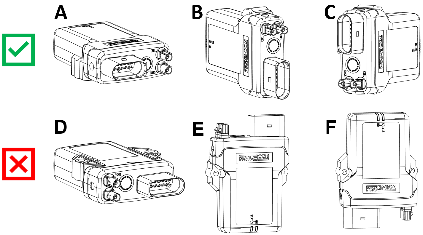
| Fire protection of the housing is only guaranteed in the installation positions shown in figures A, B or C or F. |
| Please note that fire protection is not guaranteed in the installation positions shown in figures D and E. |
|
The mounting position F fulfills the requirements of a fire protection enclosure. But is not recommended due to possible liquid ingress. |
| To avoid water ingress, please make sure that the mounting orientation of your device is either as shown in figure A, B or C. |
|
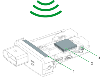
4.13.2. Antenna Positioning
The internal antennas (types 3311, 3333, 3337) are installed inside the housing on the top of the device. For the best possible reception of GNSS, Bluetooth, WLAN and mobile radio signals, the device should be mounted in the position shown here.
|
4.13.3. Mounting
Mount the device directly with 2 socket-head screws (M5) inserted in the mounting holes on the sides and screwed to the mounting surface. For detailed information on the distances between the holes, see Technical Drawings.
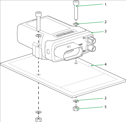
-
Socket-head screw
DIN912 - M5 x 30 mm -
Lock washer
M5, di/da = 5.3/9 mm -
CANlinkmobile
-
Screw mounting surface
D = 3 mm -
Hexagon nut
DIN934 / ISO4032 - M5
|
4.14. Installation Study
In order to ensure correct operation of the CANlink® mobile hardware when it is installed on the machine under real setup and environmental conditions, Proemion recommends performing an installation study..
The installation study ideally consists of two phases:
| # | Phase | Description |
|---|---|---|
1 |
In the initial phase of the installation study, it is essential to verify the setup requirements in regards to the specification of the CANlink® mobile. |
|
2 |
During the validation phase, the device is tested under real operating conditions and its suitability for the planned application is assessed. Several iterations and corrective actions may be required at this stage. |
4.14.1. Verification
The machine manufacturer and system integrator needs to clarify the issues according to the checklist below:
| # | Checkpoint |
|---|---|
1 |
Specify the setup and environmental conditions of the planned application at the final destination of the machine. |
2 |
Ensure that the setup conditions within the machine and the environmental conditions meet the specification of the CANlink® mobile. |
3 |
Make sure that the CANlink® mobile can be installed according to the recommendation in the chapters Cable Management and Mounting the Device. |
4 |
Check that the antenna can be installed and aligned as recommended in chapters Mobile Radio and GNSS Antenna, Antenna Positioning. |
5 |
Check that the recommended settings from chapter Power Management can be realized with the machine setup. |
|
For more information regarding the initial setup, also refer to the document CANlink® mobile 3600 Quick Start Guide at the Download Center. |
4.14.2. Validation
Once the Verification of the setup and environmental conditions regarding the specification of the CANlink® mobile was completed, it is recommended to proceed with the validation. At this stage of the system integration, the suitability of the CANlink® mobile for the above-mentioned criteria under real setup conditions must be determined. It is also advisable to evaluate the setup already in the prototype phase concerning power management, remote update ability, data consumption, remote and signal strength.
Prerequisites
Before the validation can be started, the machine manufacturer and system integrator must meet the following requirements:
| # | Prerequisite |
|---|---|
1 |
The machine and the programming of its control units correspond to the final series status. |
2 |
The machine is available for validation under real operating conditions for at least one week. |
3 |
The CANlink® mobile is installed according to Mounting the Device. |
4 |
The CANlink® mobile is wired according to Cable Management and Power Management. |
5 |
The CAN baudrate(s) of the CANlink® mobile are set correctly. The default CAN baudrate is |
6 |
The antenna is installed and aligned according to Mobile Radio and GNSS Antenna, Mobile Radio and GNSS Antenna and Antenna Positioning. |
7 |
All cables, antennas, hoses, etc. must be laid and connected. |
8 |
All housing parts of the machine must be installed according to the final series status. |
9 |
The CANlink® mobile was activated according to Provisioning / Go Live and is available with the status live within your DataPortal account. |
|
For more information regarding the initial setup, also refer to the document CANlink® mobile 3600 Quick Start Guide at the Download Center . |
Perform Installation Study
In case that the necessary prerequisites are fulfilled, it is recommended to perform an installation study under real setup and environmental conditions.
-
Login with your DataPortal user.
-
Check the firmware status of the CANlink® mobile according to chapter Firmware Management at the DataPortal User Manual. If necessary, update the firmware of the CANlink® mobile to the latest official firmware version.
Whenever a remote update is done, it is recommended to follow the instruction according to the Safe Remote Updates Guideline. -
Download the PROEMION_DemoConfig.pdc file from the Download Center and assign it to the corresponding machine model which needs to be evaluated. See also chapter PDC Management at the DataPortal User Manual.
-
Download the demo configuration for the used CANlink® mobile from the Download Center.
The PROEMION_DemoConfig.pdc and clm36xx_Proemion_DemoConfig.DOD configuration files are designed to transfer and parse a few selected standard metrics from the J1939 standard, as well as values from the internal sensors. In the installation study, in particular the acceleration values and the device temperature are taken into account. In case that the machine data is not in accordance with the J1939 standard, add the device parameters to the customized device configuration and PDC. Please get in contact with the Proemion Support for further assistance with the configuration of the test setup. -
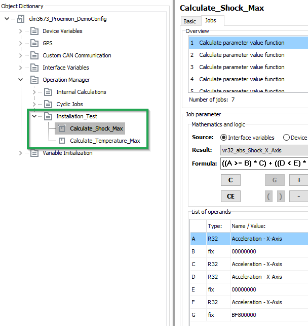
Open the clm36xx_Proemion_DemoConfig.DOD with the Proemion Configurator software. Please also refer to Configuring the Device.
-
Ensure that the configuration contains the operations Calculate_Shock_Max and Calculate_Temperature_Max.
Demo Configuration for Install Study
If the required demo configuration for your specific variant of the CANlink® mobile is not available at the Download Center yet, please get in contact with the Proemion Support. -
Adapt the configuration in regard to CAN baudrate and Power Management.
It is essential for a successful installation study and optimized data consumption, to have already a clarified concept about the required Power Management settings and the connected CAN bus. Ideally, the terminal 15 monitoring is established and there is no CAN traffic when the ignition key is off. -
Update the device configuration according to chapter Configuration update via DataPlatform.
Whenever a remote update is done, it is recommended to follow the instructions according to the Safe Remote Updates Guideline. -
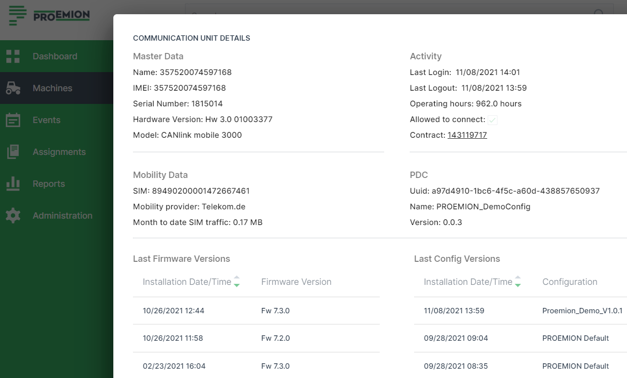
Check the status of the communication unit. See chapter Communication Details at the DataPortal User Manual manual.
Communication Unit Update History
-
Once the configuration files are installed and assigned, start with the install study under real conditions of use and monitor the parameters as mentioned in the table
Table 33. Tests for System Integration # Check 1
Ensure that the wakeup and shutdown behavior is correct and in accordance with recommended Power Management settings.
2
Ensure that the device temperature stays within the allowed range during real machine operation.
3
Monitor the maximum shock values. Perform corrective action if it turns out that there is too much vibration and shock at the installed CANlink® mobile.
4
Monitor the mobile network signal quality. Optimize the antenna position if necessary.
5
Ensure that the logged metrics from the machine are displayed correctly. Check the CAN bus connection if necessary.
6
During the system integration also monitor the current mobile network mode.
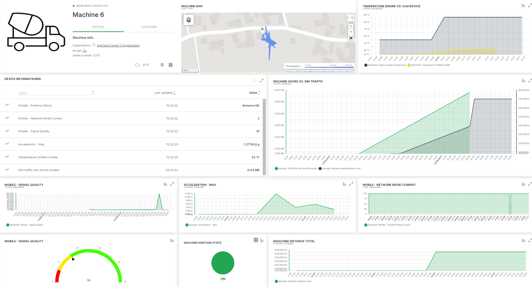 Figure 34. Dashboard for Monitoring
Please get in contact with support@proemion.com, if further assistance with adding the necessary device parameters to the logging configuration and default PDC file is required. -
Once the install study with the default configuration is completed, install and assign your customized configuration files (
.dodand.pdc). -
With the customized configuration files installed, check again the power management settings. Make sure that the device is switched on and off by the terminal 15.
-
Ensure that all configured signals are complete and transmitted correctly.
-
Check the SIM traffic in relation to the machine operation hours and transmitted signals. Make sure that the consumed data volume under real conditions of use corresponds to the selected hosting contract.
-
Carry out continuous visual checks on the hardware.
-
When the installation study is complete, ensure that CANlink® mobile has not been adversely affected in the tested mounting position.
Table 34. Additional Tests for System Integration # Check 1
Ensure that the device was not harmed by water ingress during the installation study.
2
Ensure that the housing material of device was not harmed by chemicals during the installation study.
3
Ensure that the device and its cable management was not harmed by maximum shock values.
-
In the event that the installation study has revealed any weak points, take appropriate corrective measures and repeat the installation study.
-
Perform the configuration update with the
*.dodfor the final application. Follow the instructions from the Safe Remote Updates Guideline. -
When the installation investigation has been successfully completed, adjust your device configuration PDC Management and Dashboard Management for the final application. The recording of device temperature, shock values, signal quality, etc. is not required for the customer application.
5. Operation
This chapter contains information on operating the device and the Proemion Configurator software.
5.1. Proemion Configurator
Configure the device using the Proemion Configurator. See also Customizing the demo configuration File. To alter the configuration of your device, first connect it to the PC. See Connecting the Device to the PC.
| INFORMATION |
Before you connect the device to a USB port on your PC, install the USB driver packet from the Download Center. See Installing Software.
| INFORMATION |
You can find additional information on the individual objects (device variables) in Proemion Configurator under the Additional Information field for each object.
Always use the latest version of Proemion Configurator with the updated information texts.
| TIP Download the current software version from our website. |
|
The Proemion Configurator software can be downloaded at our website: Document Library or Download Center |
| In case of problems, the Connectivity Check utility can be used to check the connectivity of our software tools with our services from your site’s network. |
5.1.1. Creating Object Dictionary Groups and Objects
You can use the Proemion Configurator tree structure to create, rename, or delete object dictionary groups or objects.
This chapter explains how to create object dictionary groups and objects.
The following example shows creation of the object RECEIVE MESSAGE PDO. This object is used to receive and log CAN messages.
To create the object, you need the CUSTOM CAN COMMUNICATION object dictionary group and then the RECEIVE CAN MESSAGES (PDOs) object dictionary group.
-
Start the Proemion Configurator software.
-
Choose FILE > OPEN from the menu.
-
Open the configuration file you want.
-
Right-click on the top entry in the tree structure to open the context menu.
-
In the context menu, click on NEW OBJECT DICTIONARY GROUP > CUSTOM CAN COMMUNICATION.
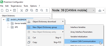 Figure 35. Object Dictionary Group - CUSTOM CAN COMMUNICATION
 -
Right-click on the object dictionary group CUSTOM CAN COMMUNICATION.
-
In the context menu, click on NEW OBJECT DICTIONARY GROUP > RECEIVE CAN MESSAGES (PDOs)
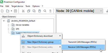 Figure 36. Object Dictionary Group - RECEIVE CAN MESSAGES (PDOS)
 -
In the context menu, click on NEW OBJECT DICTIONARY ENTRY > RECEIVE MESSAGE PDO.
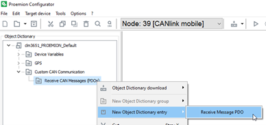 Figure 37. NUMBER OF NEW OBJECTS AND THEIR VERSION
 -
In the NUMBER OF NEW OBJECTS field, enter how many objects (received messages) you want to create.
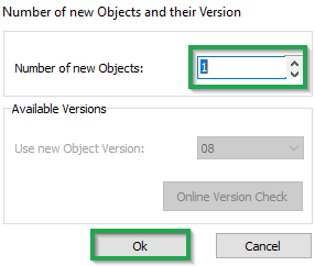 Figure 38. NUMBER OF NEW OBJECTS
 -
Click OK.
✓ The object RECEIVE MESSAGE PDO is created.
-
To rename an entry in the tree structure, click on the corresponding entry to select it. Click on the entry again to rename it.
5.2. Logging Mode
In Logging mode, the device logs CAN messages, GNSS data, and internal variables.
All the recorded data is saved in an internal, nonvolatile memory and automatically sent to the DataPlatform when a connection is available.
|
|
|
|
For further information on the DataPortal functionality, refer to the Document Library. |
5.2.1. Configuring Logging mode
-
Start the Proemion Configurator software.
-
Choose FILE > OPEN from the menu.
-
Open the configuration file you want.
-
Click on the DEVICE MODE (CONFIGURED) variable in the DEVICE VARIABLES object dictionary group.
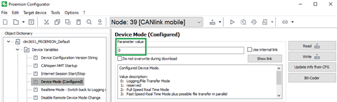 Figure 39. DEVICE VARIABLES Object Dictionary
 -
In the DEVICE MODE (CONFIGURED) field, enter the value 0.
✓Logging mode is enabled.
|
5.2.2. Configure automatic switch back to logging mode
The device is equipped with an automatic switchover function from RealTime to Logging mode.
Usually,the device is set to Logging mode and transmitting data to the DataPlatform. In case that a service engineer needs to establish a Realtime session for getting access to the CAN bus, the device is switched from Logging mode to RealTime mode. When the Realtime session was stopped, the device will automatically switch over to the Logging mode after a specified period. This will avoid a lack of logging data when the service engineer does not switch the device back to Logging mode when it is finished.
You can enable the automatic switchover function and determine a period (unit: minutes). If no RealTime signal is received from a RealTime client software within this period, the device automatically switches back to Logging mode.
-
Right click on DEVICE VARIABLES and select NEW OBJECT DICTIONARY ENTRY > DEVICE VARIABLES.
-
When the DEVICE VARIABLES object dictionary group is open, add the REAL TIME MODE - SWITCH BACK TO LOGGING MODE TIME object to it.
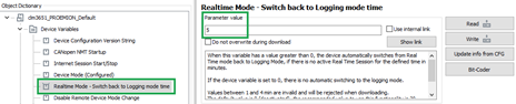 Figure 40. REALTIMEMODE -SWITCH BACK TO LOGGING MODE TIME
 -
Enter the required value in the REALTIME MODE - SWITCH BACK TO LOGGING MODE TIME field.
-
Click on the SAVE CHANGES button to save the change.
✓ The automatic switchover function is enabled.
|
5.2.3. Configuring variables for CAN communication
To enable CAN communication and data logging, you must configure the following variables.
CAN Settings
The variables required concern the CAN connection and belong to the object dictionary group DEVICE VARIABLES.
| Variable | Value | Function |
|---|---|---|
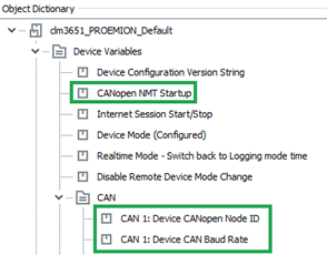
CANOPEN NMT STARTUP |
|
Automatically sets the device to CANopen mode "Operational". |
CAN1/CAN2/CAN3:DEVICE CANOPEN NODE-ID |
|
The CANopen node address (can be left at the standard value). |
CAN1/CAN2/CAN3:DEVICE CAN BAUD RATE |
min. 50 kbit/s; max. 1 Mbit/s |
The baud rate at which the CAN bus operates. |
Logging Variables
The variables required concern the logfile and belong to the DEVICE VARIABLES > LOGGING object dictionary group.
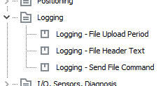
| Variable | Function |
|---|---|
LOGGING – FILE UPLOAD PERIOD |
Period in which the logfile is completed and sent to the DataPlatform. `value = 0 ` → data is sent when the size of the logfile reaches 1 kB. |
LOGGING – FILE HEADER TEXT |
Information text in the header of each logfile. Can contain version information for instance (max. 32 characters). |
LOGGING – SEND FILE COMMAND |
Assign any value to the variable during operation in order to immediately close and transfer the existing logfile. |
|
5.2.4. CAN logging Example 1 - Cyclic logging
In the following, the example of a J1939 message is used to explain the general procedure for configuring CAN reception messages.
The procedure can also be applied to other CAN messages from other CAN protocols.
For detailed information on creating objects, see Creating Object Dictionary Groups and Objects.
CREATING A PGN 61444
-
Create the object dictionary group CUSTOM CAN COMMUNICATION > RECEIVE CAN MESSAGES (PDOS) .
-
Create the RECEIVE MESSAGE PDO object in the RECEIVE CAN MESSAGES (PDOS) object dictionary group you have created.
-
Rename the RECEIVE MESSAGE PDO object to PGN 61444.
RECEIVE MESSAGE COMMUNICATION PARAMETERS
-
Select the COMMUNICATION tab
-
Make the following settings.
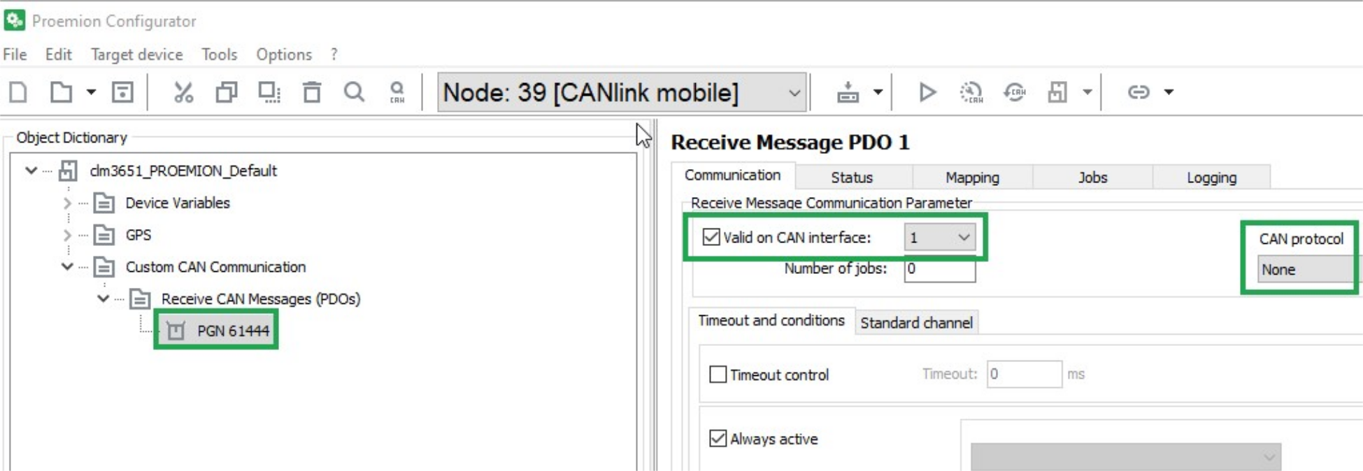
| Description | Selection | Function |
|---|---|---|
VALID ON CAN INTERFACE |
Set |
Enabling the configuration, defining the CAN interface for reception (if several are available). |
CAN PROTOCOL |
None |
The received CAN message is a single message (Layer 2). It is not treated according to a superordinate CAN protocol. |
TIMEOUT AND CONDITIONS
Select the TIMEOUT AND CONDITIONS tab.
Make the following settings.
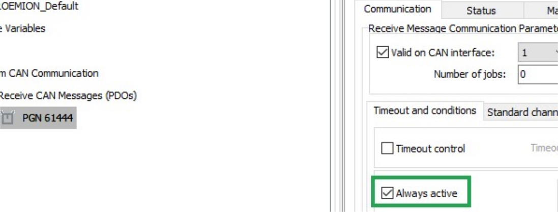
| Description | Selection | Function |
|---|---|---|
ALWAYS ACTIVE |
Set |
The CAN message is received irrespective of events or conditions. |
STANDARD CHANNEL
Select the STANDARD CHANNEL tab.
Make the following settings.
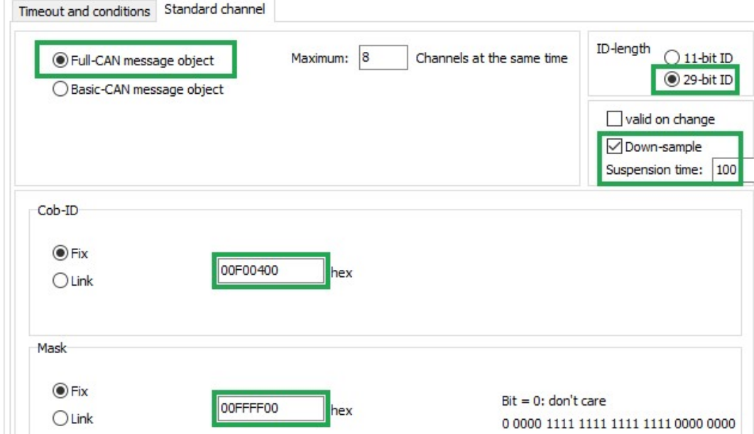
| Description | Selection | Function |
|---|---|---|
FULL CAN MESSAGE OBJECT |
Set |
Assigns the receive message to a controller channel. |
ID-LENGTH |
29-bit ID |
ID length of the CAN message to be received. |
DOWN-SAMPLE |
Set |
Receive message max. every 100 ms. |
COB-ID |
Fix ( |
Fixed identifier of the receive message (J1939 PGN 61444). |
MASK |
Fix ( |
Determines that bits 8 … 24 of the identifier fixed in COB-ID must not vary in the identifier of the received message. In the J1939 protocol, the first bits of the identifier define the priority and the last bits of the identifier define the source address. These are ignored when the message is received. |
LOG ALL DATA BYTES EVERY 60 SECONDS
In this example, all data bytes are simply logged cyclically every 60 seconds. There are no additional conditions, and the data bytes are not checked.
LOGGING - CONDITIONS
Define the following settings for the PGN 61444 object.
Select the LOGGING tab.
Select the CONDITIONS tab.
Make the following settings.
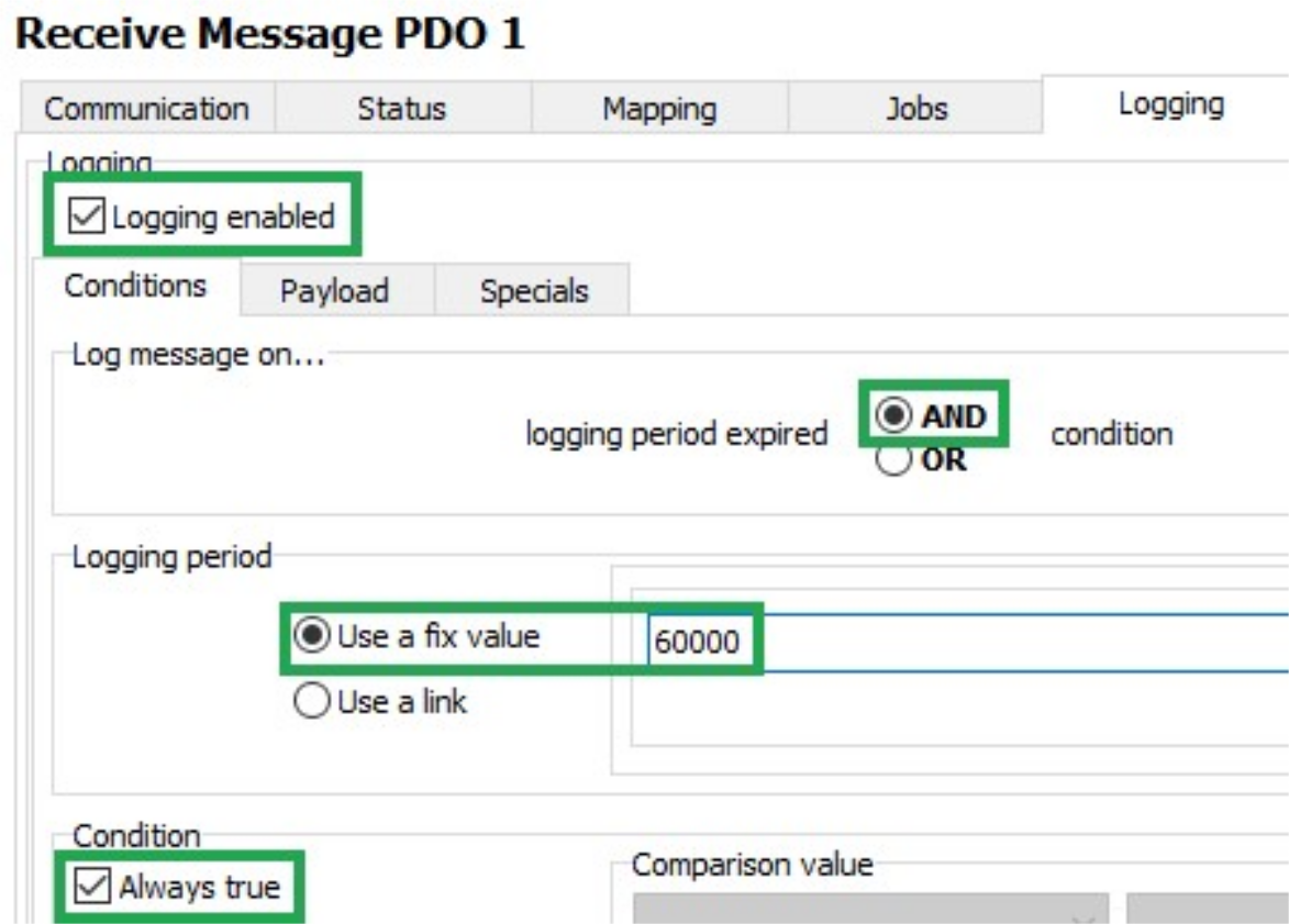
| Description | Selection | Function |
|---|---|---|
LOGGING ENABLED |
Set |
Logging enabled |
LOG MESSAGE ON |
AND |
The data is only logged when timeout is reached AND the condition is met. |
LOGGING PERIOD |
Use a fixed value ( |
Duration of the logging interval in milliseconds. |
CONDITION / ALWAYS TRUE |
Set |
Logging takes place without prior checking of conditions. |
Payload
Select the PAYLOAD tab.
Make the following settings.
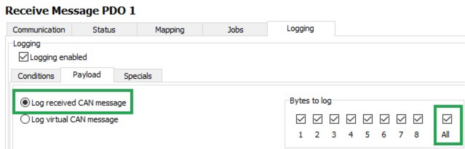
| Description | Selection | Function |
|---|---|---|
LOG RECEIVED CAN MESSAGE |
Set |
Log data of the receive CAN message. |
BYTES TO LOG |
All |
Log all data bytes. |
Click on the SAVE button.
Load the configuration to the device. See Loading the Configuration to the Device via CAN Interface.
✓ You have completed the configuration for logging of all data bytes of the J1939 PGN 61444 every 60 seconds.
5.2.5. CAN logging Example 2 – Logging specific data bytes under certain conditions
In this example, specific data bytes are logged under defined conditions.
Data bytes 2 … 5 and 8 of the CAN messages received are logged when the engine speed (data bytes 4 and 5) changes by ± 500 rpm, or every 10 minutes.
A received CAN message is processed with the following functions:
-
Mapping
-
Jobs
-
Logging
VARIABLES
If you want to log data under defined conditions, you need certain variables for checking values.
These variables belong to the INTERFACE VARIABLES object dictionary group.
Create the INTERFACE VARIABLES object dictionary group.
In the INTERFACE VARIABLES object dictionary group, create four new INTERFACE VARIABLE objects.
✓ The LIST OF INTERFACE VARIABLES window opens.
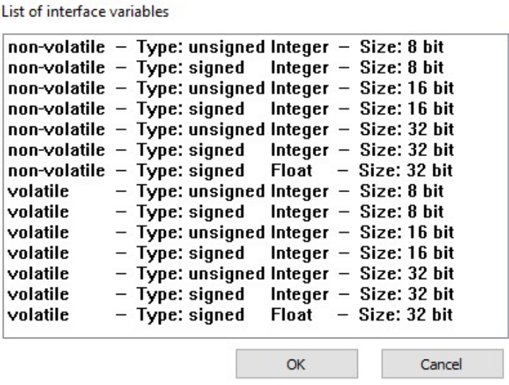
Select the first INTERFACE VARIABLE object according to the following table.
| Designation | Type | Sign | Size |
|---|---|---|---|
volatile U8 Trigger |
volatile |
unsigned |
8 bits |
volatile S32 Engine Speed new |
volatile |
signed |
32 bits |
volatile S32 Engine Speed old |
volatile |
signed |
32 bits |
non-volatile U16 threshold value |
non-volatile |
unsigned |
16 bits |
Click on the OK button.
✓ The INTERFACE VARIABLE object with the selected settings is created.
Repeat this procedure for the other three INTERFACE VARIABLE objects.
Rename the four INTERFACE VARIABLE objects according to the table.
Define a threshold value for the NON-VOLATILE U16 THRESHOLD VALUE object.
✓ The four INTERFACE VARIABLE objects are displayed
LOGGING - CONDITIONS
Define the following settings for the PGN 61444 object.
Select the LOGGING tab.
Select the CONDITIONS tab.
Make the following settings.
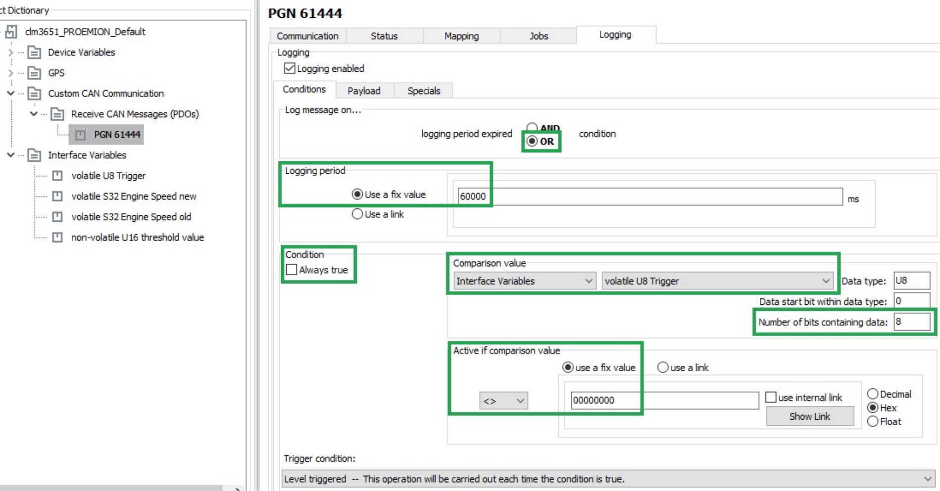
| Description | Selection | Function |
|---|---|---|
LOG MESSAGE ON |
|
The data is logged when timeout is reached OR the condition is met. |
LOGGING PERIOD |
Use a fixed value ( |
Duration of the logging interval in milliseconds. |
CONDITION / ALWAYS TRUE |
not set |
The data is logged depending on the result of the check. |
COMPARISON VALUE |
|
Logging depends on the VOLATILE U8 TRIGGER variable. |
NUMBER OF BITS CONTAINING DATA |
|
All 8 bits of the variable are compared with COMPARISON VALUE. |
ACTIVE IF COMPARISON VALUE |
|
Data is only logged if the variable VOLATILE U8 TRIGGER is not equal to 0. |
TRIGGER CONDITION |
Level triggered - This operation will be carried out each time the condition is true. |
Logging is enabled as long as the variable VOLATILE U8 TRIGGER is not equal to 0. |
PAYLOAD
Select the PAYLOAD tab.
Define the following settings.
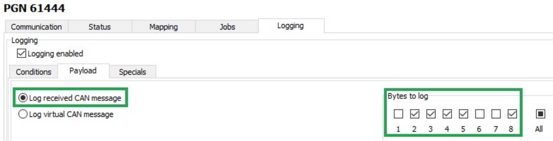
| Description | Selection | Function |
|---|---|---|
LOG RECEIVED CAN MESSAGE |
Set |
Log data of the receive CAN message. |
BYTES TO LOG |
2 … 5 and 8 |
Logging selected data bytes |
MAPPING - ACTIVE CONDITION
During mapping, data is copied from the CAN message to variables. You can then process the copied data in the device and perform calculations.
Select the MAPPING tab.
Select the ACTIVE CONDITION tab.
Define the following settings.
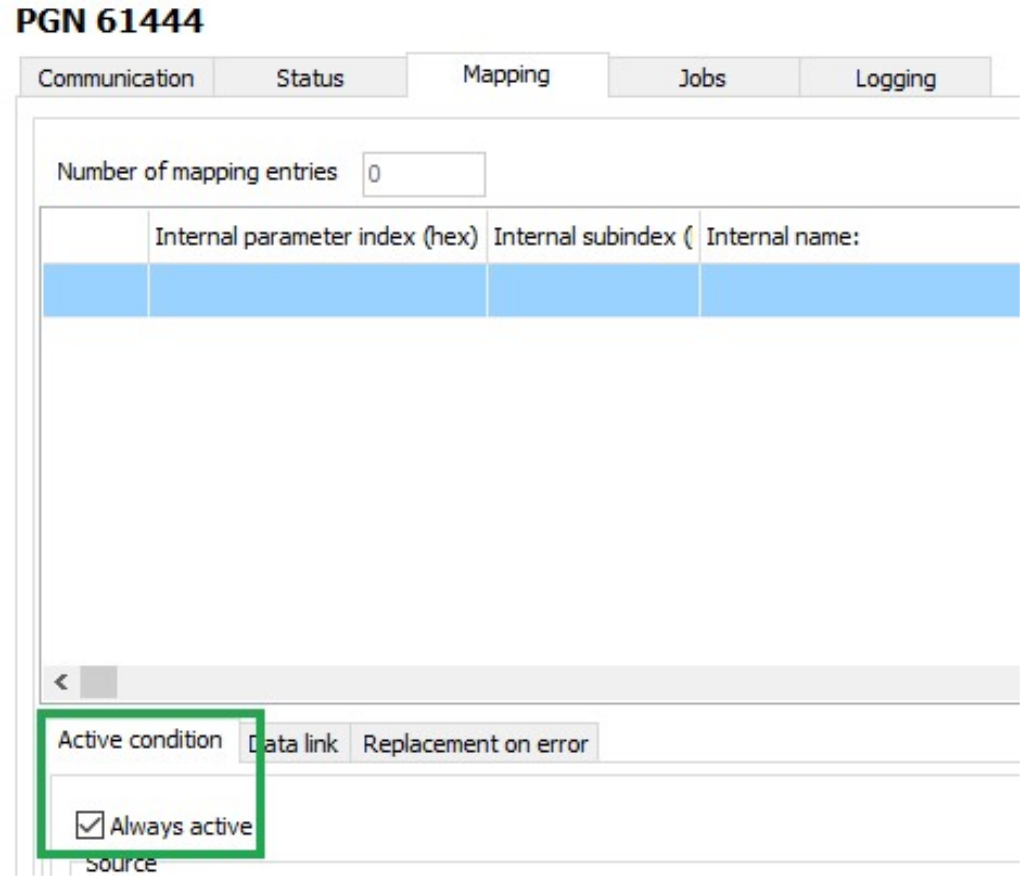
| Description | Selection | Function |
|---|---|---|
ALWAYS ACTIVE |
Set |
Mapping always takes place without conditions. |
DATA LINK
Select the DATA LINK tab.
Define the following settings.
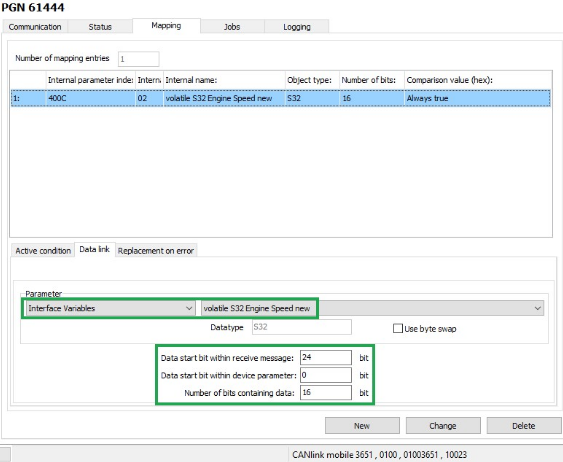
| Description | Selection | Function |
|---|---|---|
PARAMETER |
volatile S32 Engine Speed new |
The data is written to the VOLATILE S32 ENGINE SPEED NEW variable. |
DATA START BIT WITHIN RECEIVE MESSAGE |
24 bits |
The data used starts with bit 24 (from the 4th byte). |
DATA START BIT WITHIN DEVICE PARAMETER |
0 bits |
The data used begins from bit 0 |
NUMBER OF BITS CONTAINING DATA |
16 bits |
The data used has 16 bits (2 bytes). |
Click on the NEW button to create the mapping entry.
✓ The mapping entry is adopted in the table.
✓ The data is copied into the internal variable on reception of a CAN message.
JOBS
Every time a CAN message is received, jobs are performed after mapping and before logging.
In the JOBS tab, configure the calculation operations you need for your job.
For the example configuration, you need two jobs with the function CALCULATE PARAMETER VALUE FUNCTION. With this function, you perform calculation operations and overwrite interface variables with calculated values.
JOB 1
With the first job, you check whether the current speed is above or below the threshold value. If one of these two cases applies, the VOLATILE U8 TRIGGER variable should be set to the value 1. This triggers logging of the CAN message.
-
Select the JOBS tab.
-
In the CURRENT FUNCTION OF SELECTED JOB list, select the function CALCULATE PARAMETER VALUE FUNCTION.
-
In the RESULT list, select the trigger VOLATILE U8 TRIGGER.
-
Using the buttons in the MATHEMATICS AND LOGIC section, enter the calculation operations
(A < (B – C)) or (D > (E + F)). -
Click on button A.
INFORMATION
If you click on a placeholder (e.g. A), this opens the window INPUT OPERAND INFORMATION OR OPEN A NEW OPERATION.
You can find the allocation of the variables for this example in the table below. -
Click on the variable in the list that you want to allocate the placeholder to.
-
Click on the CHANGE button when you have entered the calculation operations completely.
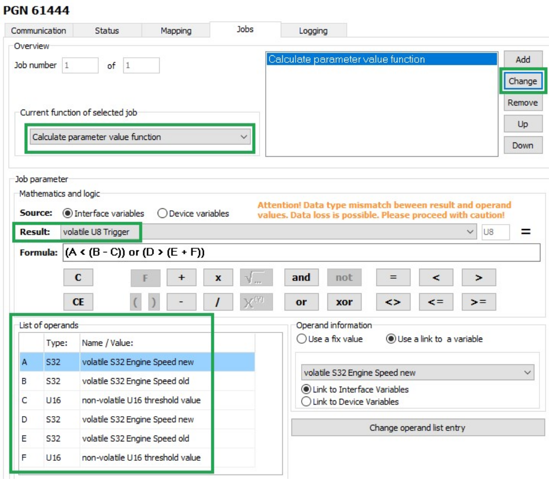
-
Allocate the following variables to the placeholders:
| Variable | Type | Name/value |
|---|---|---|
A |
S32 |
volatile S32 Engine Speed new |
B |
S32 |
volatile S32 Engine Speed old |
C |
U16 |
non-volatile U16 threshold value |
D |
S32 |
volatile S32 Engine Speed new |
E |
S32 |
volatile S32 Engine Speed old |
F |
U16 |
non-volatile U16 threshold value |
The buttons for entering the calculation operations have the following functions:
| Buttons | Description | ||||
|---|---|---|---|---|---|
|
|
||||
|
Add variables to the calculation operation.Click on the button to open a window. Assign fixed values, interface variables or device variables to the variables. After you have defined a variable, the display on the button switches to the next variable. |
||||
|
Basic calculation types ( |
||||
|
On integer numbers, the operation is performed bitwise. If the operators only contain the values 0 or 1, the operation can be considered a logical calculation.
If the operand is 0, the expression evaluates to 1. If the operand is unequal to 0, the expression evaluates to 0.
|
||||
|
Comparative value ( |
||||
|
Brackets |


|
JOB 2
In the second job, you replace the value of the VOLATILE S32 ENGINE SPEED OLD variable with the value of the VOLATILE S32 ENGINE SPEED NEW variable as soon as the VOLATILE U8 TRIGGER variable has the value 1.
This updates the speed from which the deviation should be detected.
This updates the speed from which the deviation should be detected.
-
Select the JOBS tab.
-
In the CURRENT FUNCTION OF SELECTED JOB list, select the function CALCULATE PARAMETER VALUE FUNCTION.
-
In the RESULT list, select the trigger VOLATILE S32 ENGINE SPEED OLD.
-
Using the buttons in the MATHEMATICS AND LOGIC section, enter the calculation operations
((A <> B) * C) + ((D = E) * F). -
Click on button A.
INFORMATION If you click on a placeholder (e.g. A), the window INPUT OPERAND INFORMATION OR OPEN A NEW OPERATION opens. You can find the allocation of the variables for this example in the table below. -
Click on the variable in the list that you want to allocate the placeholder to.
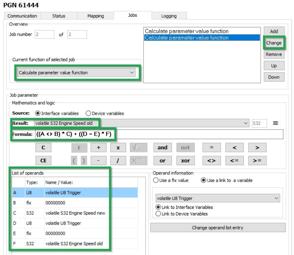
-
Allocate the following variables to the placeholders:
Table 49. Variables - Job 2 Variable Type Name/value A
U8
volatile U8 Trigger
B
fix
00000000C
S32
volatile S32 Engine Speed new
D
U8
volatile U8 Trigger
E
fix
00000000F
S32
volatile S32 Engine Speed old
-
Click on the NEW button when you have entered the calculation operations completely.
-
Click on FILE > SAVE in the menu.
-
Load the configuration to the device. See Chapter Loading the configuration to the device.
✓ You have completed the configuration for logging specific data bytes.
5.2.6. CAN logging Example 3 - On Change Logging
On receipt of CAN messages whose content seldom changes, you can activate the VALID ON CHANGE option.
If the option is activated, a CAN message received is only recorded by the device if a value within the data bytes has changed.
This option can be activated for standard 11-bit and 29-bit CAN messages as well as for J1939 CAN messages.
|
-
Navigate to the COMMUNICATION section.
-
Move to the STANDARD CHANNEL section and click to enable the VALID ON CHANGE option.
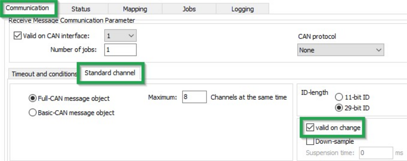
-
Navigate to the LOGGING section.
-
Move to the LOGGING section and click to tick the LOGGING ENABLED option.
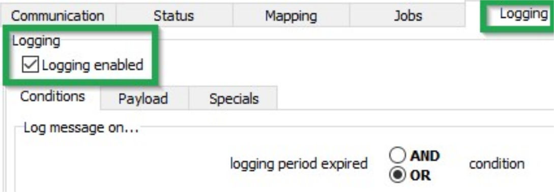
✓ CAN messages received with a modified content are recorded.
5.2.7. Logging GNSS position data
The GNSS position data contains information on longitude and latitude, altitude and direction as well as speed, time and date.
Data is only logged when valid position data is received.
Define the following settings:
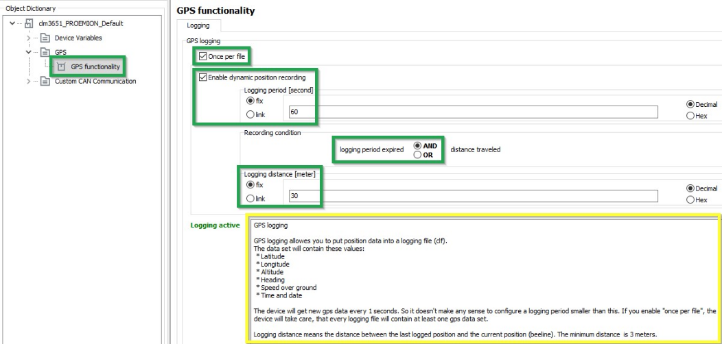
| Variable | Function |
|---|---|
ONCE PER FILE |
Each logfile contains position data at least once. |
ENABLE DYNAMIC POSITION RECORDING |
Enables/ Disables the position data logging. |
LOGGING PERIOD (SEC) |
Time period during which the position data should be logged. |
AND / OR |
|
LOGGING DISTANCE (METERS) |
Distance between the last position logged and the current position (linear distance). |
|
5.2.8. Configuring the logging of internal variables
You can log various internal variables. Internal variables can be both device variables and interface variables.
To log internal variables, you need an ACTION - FUNCTION - OPERATION object in the OPERATION MANAGER object dictionary group. With the object ACTION – FUNCTION – OPERATION, up to 8 internal variables can be logged in one process as a virtual CAN message.
-
Start the Proemion Configurator software.
-
Choose FILE > OPEN from the menu.
-
Open the desired configuration file.
-
Create an OPERATION MANAGER object dictionary group.
-
Create an ACTION - FUNCTION - OPERATION 1 object in the OPERATION MANAGER object dictionary group.
-
Select the BASIC tab.
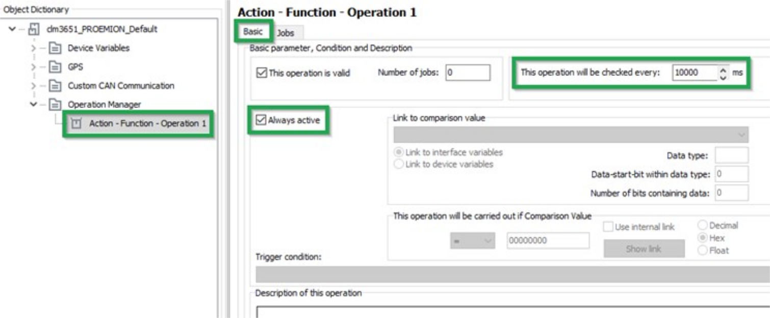
-
Enter a value in milliseconds in the THIS OPERATION WILL BE CHECKED EVERY field. This value determines the intervals at which the variables are logged.
-
Check the ALWAYS ACTIVE box. Logging takes place irrespective of conditions. Alternatively, you can define conditions for logging.
-
Click on the SAVE button.
-
Select the JOBS tab.
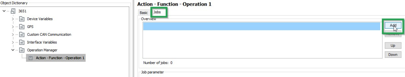
-
In the OVERVIEW field, click on the ADD button.
✓ The CREATE NEW JOB window opens.
-
Select the LOGGING job type.
-
Click on the OK button.
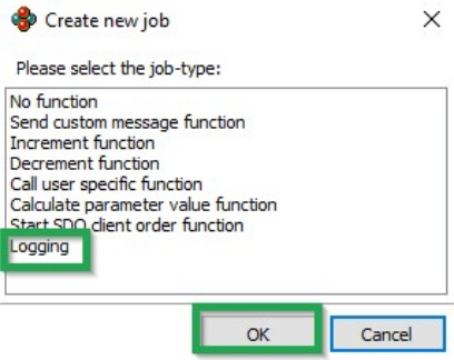
-
In the COBID field, enter the ID (hex) for the virtual CAN message. The ID must not be used by other CAN messages.
-
In the ADD NEW ROW field, select the variable type and the variable.
-
In the JOB PARAMETER field, click on the ADD button.
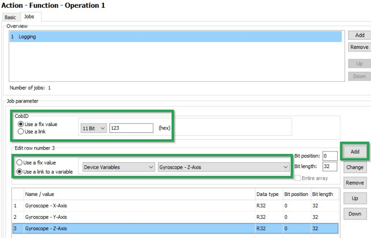
-
Add further variables if required.
-
Click on FILE > SAVE in the menu.
✓ You have completed the configuration for logging of internal variables.
5.2.9. Evaluating the data logged on the DataPlatform
WRITING A PARSING CONFIGURATION FILE (PDC) AND ASSIGNING IT TO A MACHINE
In order to be able to evaluate the logged messages and display the signals on the DataPlatform, you must create an additional configuration file (PDC file) and assign it to the device on the DataPlatform.
| INFORMATION A detailed description on how to create a PDC file, can be found at the PDC Manual. |
5.3. RealTime Mode
In RealTime mode, CAN messages are transmitted bidirectionally.
CAN messages and GNSS data can be transmitted close to RealTime.
Alternatively, the device can use a WLAN or Bluetooth connection to receive and transmit data from an external receiver, e.g. the CANlink wireless.
Configuration is done with the Proemion Configurator. The basics are described in Configuring RealTime mode.
|
|
For further information on the DataPortal functionality, refer to the DataPortal DataPortal User Manual. |
5.3.1. Configuring RealTime mode
-
Start the Proemion Configurator software.
-
Choose FILE > OPEN from the menu.
-
Open the configuration file you want.
-
Click on the DEVICE MODE (CONFIGURED) variable in the DEVICE VARIABLES object dictionary group.
-
In the DEVICE MODE (CONFIGURED) field, enter the value 2.
✓ You have configured the RealTime mode.
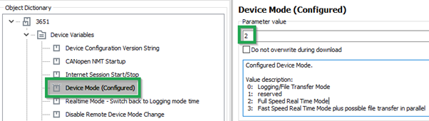
|
5.3.2. Creating a RealTime Connection and Evaluating CAN messages
For a RealTime connection and evaluation of CAN messages, you can use the Remote Service Tool software.
|
For more information on how to configure and use the Remote Service Tool software, refer to the Remote Service Tool Manual. |
5.3.3. Setting a Reception Filter
You can filter CAN messages for transmission to the DataPlatform.
Set the filters by using the Remote Service Tool software.
|
For more information on how to configure and use the Remote Service Tool software, refer to the Remote Service Tool Manual. |
5.4. File Transfer
You can use the device to transfer files between the DataPlatform and the machine’s CAN open network.
5.4.1. Transfer User File via the DataPlatform
Performing controller updates without being physically on-site is an increasingly important application for many OEMs. This chapter describes how a user file can be transferred from the Proemion DataPlatform via internet and cellular network to a CANlink® mobile and from there to an ECU via CAN Bus.
A common use case for this function could be a parameter update of the ECU. The update file is loaded remotely into the CANlink® mobile and stored within the internal filesystem. An external device can then download the file by using SDO commands on the CAN bus. The CANlink® mobile only acts as a gateway with an integrated CANopen file server. Please be aware that the transferred files are not checked or controlled in any way by the CANlink® mobilee itself. So, the files must be checked and processed by the target device (ECU).
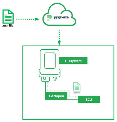
|
Upload the File from the DataPlatform to the CANlink® mobile
-
Please make sure that your DataPortal user has the permission set
machine–adminassigned. -
Login to your Proemion DataPortal Account.
-
Go to > Administration > Transfers (1).
-
Click on UPLOAD FILE (2).
-
Select the desired machine (3).
-
Select the desired
*.usrfile for upload (4). -
Click on UPLOAD (5).
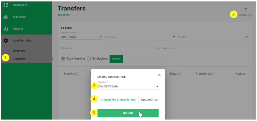
✓ The uploaded file will appear in the file transfer list after successful upload.
✓ The DataPlatform manages the file transfer to the selected machine (CANlink® mobile) automatically as soon as the device is ready to receive the file.
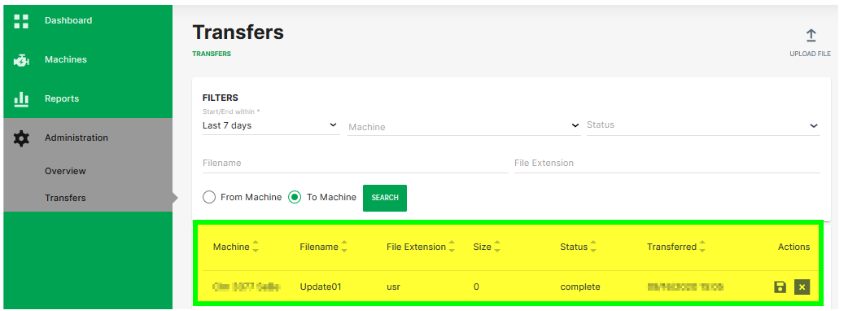
|
Transfer the file from the CANlink® mobile to the ECU via CAN
The CANlink® mobile has an internal file system that can be accessed by CANopen SDO commands. The protocol for the file handling communication on CAN Bus is CANopen. SDO requests and the SDO block transfer protocol are used to exchange commands and payload.
|
-
As indication that a new file had been received by the CANlink® mobile, the device variable with index
0x5402sub index0x01is automatically set to0x01. Herewith any ECU on the CAN network can poll the status of this device variable to monitor the reception of new files. -
In the next step the ECU must check the name of the available files which were uploaded to the CANlink® mobile. This is done by writing the command string
lsinto device variable with Index0x4444Sub Index0x01. -
Check the status of this command. Read out the device variable with Index
0x4444Sub Index0x03. The status should be3(=LIST). -
Read out the content of device variable with Index
0x4444Sub Index0x02. This will give you the exact file name. -
The download of the specific file to the ECU can be triggered by writing the command string
rd “[file_name]”into device variable with Index0x4444Sub Index0x01. -
Check the status of this command. Read out the device variable with Index
0x4444Sub Index0x03. The status should be2(=READ). -
To download the file content, read out the domain of device variable with Index
0x4444Sub Index0x02. -
Once the downloaded file has been processed successfully at the ECU, it should be deleted in the CANlink® mobile by writing the command string
del “[file_name]”into the device variable with Index0x4444Sub Index0x01. -
To enable the download of a new file, the device variable with Index
0x5402, Sub Index0x01must be set to0x00.
|
5.4.2. Generic File Transfer
Transferring a File to the DataPlatform
A simple transfer of files up to 128k Byte via the CAN bus to the DataPlatform is implemented in the device. The files are saved in the device in an internal nonvolatile memory and automatically transferred to the DataPlatform when a server link is established.
The following steps are required for the transfer:
-
An external device transfers a file using the CANopen SDO protocol to the object
0x5421, 0x03of the CANlink® mobile:
DEVICE VARIABLES > FILE TRANSFER TRANSMIT - FILE DATA - CACHED MODE -
An external device transfers the file name using the CANopen SDO protocol to the object
0x5420, 0x03of the CANlink® mobile as a string in the format 8.3 (see File Transfer Restrictions):
DEVICE VARIABLES > FILE TRANSFER TRANSMIT - FILENAME - CACHED MODE -
An external device writes the value 1 to the object
0x5422, 0x03of the CANlink® mobile which triggers automatic file transfer to the DataPlatform:
DEVICE VARIABLES > FILE TRANSFER TRANSMIT - COMMAND - CACHED MODE
You can find out the current free memory space available using the object 0x5423, 0x04 (DEVICE VARIABLES > FILE TRANSFER TRANSMIT - GET FREE SPACE - CACHED MODE). If memory space is available, several files can be logged in the device. The files are then automatically transmitted to the DataPlatform in the order in which they were written to the device.
For detailed information on creating objects, see Creating Object Dictionary Groups and Objects.
Reading a File Transferred by the DataPlatform
The DataPlatform can transfer files in segments of 1024 bytes each via the device. The files transferred by the DataPlatform are saved to a CANopen control unit in the device in an internal, volatile memory and can be read out of the device by the CANopen network.
Proceed as follows to be able to read out files transferred from the DataPlatform.
-
Check that the object
0x5402, 0x00has the value0x01. This value indicates that a file has been transferred to the device from Proemion.
FILE TRANSFER RECEIVE - INDICATION -
If the object has the value
0x01, you can read the file name from the object0x5400, 0x00.
FILE TRANSFER RECEIVE - FILENAME -
Read off the file from the object
0x5401, 0x00.
FILE TRANSFER RECEIVE - FILE -
When the file has been read out, write the value 0 in the object
0x5402, 0x00. FILE TRANSFER RECEIVE - INDICATION
✓ The device is then ready to receive a new file from the DataPlatform.
For detailed information on creating objects, see Creating Object Dictionary Groups and Objects.
File Transfer Restrictions
Restrictions apply to file transfer. The following conditions must be met:
-
The file names must have 8 characters and the file extension must have 3 characters (8.3 format).
-
Characters permitted for the file name and file extension are :
"A", … "Z","a", … "z"and"0", … "9" -
The following file extensions are reserved for internal use only and may not be used for customer application:
.obr,.obw,.obc,.dbs,.prg,.bin,.clf,.msg
If these conditions are not met, the file will be rejected by the device and/or DataPlatform.
This blocks transmission in both directions. To clear the blockage, you must delete the faulty file from the DataPlatform or from the file transfer.
|
Further information on how to delete faulty files from the DataPlatform can be found here: DataPortal User Manual > File Transfer. |
5.5. CANopen File Server
The CANlink mobile offers a local nonvolatile file storage that can be accessed by CANopen SDO. This functionality for example is used for providing ECU update files to the machine received from the DataPlatform. Please also refer to Transfer User File via the DataPlatform.
The following functions are available for data access via the SDO:
| Function Code | Option | Description |
|---|---|---|
|
|
Write in file (always in Append mode) |
|
|
Delete file or directory |
|
|
Read out of file |
|
List file or directory |
|
|
|
Change directory |
| File or path names that contain a space must be placed in quotation marks. |
|
|
|
The following functions are available following data access via CANopen:
| Index | Subindex | Meaning | Data Type | Description |
|---|---|---|---|---|
|
|
Command |
|
See function descriptions. Please be aware that the maximum accessible file path size is 253 characters. |
|
|
Data |
|
See function descriptions |
|
|
Status |
|
The following states are displayed: |
|
|
Available size |
|
Memory space available on file system in bytes |
|
|
File size |
|
Size of current file selected, in bytes |
|
|
Status |
|
The following states are displayed: |
|
5.5.1. Function Description
The following sections describe the individual functions and structure of the respective commands.
When entering commands, pay attention to the correct spelling and notation.
If spaces are contained, the path and file input must be set in quotation marks. If no spaces are contained, the use of quotation marks is optional.
WR - Write
-
Structure of the command:
wr "path\name"
If the wr command is written to the command object, the device checks whether a file with this name exists. If no file is available, a new one is created.
An error code appears in the status object if the file cannot be opened to be written to or an error occurs.
The current file size is displayed in the file size object. The data content can then be written in the data object.
After completing the write operation to the data object, the file is automatically closed and the command deleted.
Directories can also be created with this command.
|
|
DEL - Delete
-
Structure of the command:
del "path\name"
If the del command is written to the command object, the device checks for existing files with this name. If the file exists, it will be deleted.
An error code appears in the status object if the file cannot be deleted or an error occurs.
When the process is completed, the command is deleted.
Directories can also be deleted in this way.
RD - Read File
-
Structure of the command:
rd "path\name" [-o n] [-l m]
If the rd command is written to the command object, the device checks for existing files with this name.
An error code appears in the status object if the file does not exist or an error occurs.
The file size object displays the size of the current file. The data content can be read out of the data object.
After completing the read operation from the Data object, the file is automatically closed, and the command deleted.
The following options are available with this command:
-
-o n- Offset: n bytes
The read process starts at the byte-position specified. Decimal or hexadecimal values are possible. -
-l m- Length: m bytes
The number of bytes specified (maximum till the end of the file) is read out of the file. Decimal or hexadecimal values are possible. To specify hexadecimal value use the prefix0x, for example0xA.
|
LS - List file or directory
-
Structure of the command:
ls
If the ls command is written to the command object, a file and directory list can be read out of the data object.
Directory names are identified by < and >. A line feed [CRLF] occurs after each entry.
When the read operation from the Data object is completed, the command is deleted.
|
CD - Change Directory
-
Structure of the command:
cd ["path"], [..], [\]
If the cd command is written to the command object, the device checks whether a directory with this name exists. If a directory with this name exists, it is opened.
An error code appears in the status object if the directory does not exist or an error occurs.
When the process is completed, the command is deleted.
The following options are available with this command:
-
"path"- Change to the directory specified. -
..- Change to the directory level one level higher. -
\- Change to the root directory.
5.6. Encrypted Data Transfer
The device supports encrypted data transfer to the DataPlatform according to the TLS standard (Transport Layer Security).
Encrypted data transfer is already enabled when the device is delivered.
The variables required belong to the DEVICE VARIABLES object dictionary group.
| Variable | Function |
|---|---|
ENABLE ENCRYPTED DATA TRANSFER |
|
REMOTE SERVER PORT |
|
|
|
5.7. Important device variables
This chapter provides information on important device variables that control the device functions.
5.7.1. Positioning
The device is equipped with a GNSS receiver. The GNSS receiver can process signals from the following satellite navigation systems:
-
GPS
-
GLONASS
-
BEIDOU
Set the combination of the satellite systems in the POSITIONING > MODE (GNSS) variable. The POSITIONING > MODE (GNSS) variable belongs to the DEVICE VARIABLES > POSITIONING object dictionary group.
| Variable | Function |
|---|---|
POSITIONING - MODE (GNSS) |
|
| Variable | Function |
|---|---|
POSITIONING – ANTENNA STATUS |
Status of the antenna |
POSITIONING - POSITIONING DATA VALID |
Status of the position system. Indicates whether valid position data is available |
POSITIONING - ACTIVE SATELLITES |
Number of satellites used |
POSITIONING - LONGITUDE |
Longitude |
POSITIONING - LATITUDE |
Latitude |
POSITIONING - ALTITUDE |
Altitude of the antenna above sea level |
POSITIONING - SPEED OVER GROUND |
Speed over ground |
POSITIONING - GPS ODOMETER |
GPS-based measurement of kilometers traveled |
POSITIONING - HEADING |
Direction in relation to North |
5.7.2. WLAN and Bluetooth
Some types of the device are equipped with a radio module for WLAN and Bluetooth.
The DEVICE VARIABLES > LOCAL WIRELESS object dictionary group contains the following variables:
| Variable | Function |
|---|---|
WLAN - ENABLE |
Enable and disable the WLAN interface |
BLUETOOTH - ENABLE |
Enable and disable the Bluetooth interface |
WLAN - MAC ADDRESS |
MAC address of the WLAN interface |
BLUETOOTH - MAC ADDRESS |
MAC address of the Bluetooth interface |
WLAN/BLUETOOTH - FIRMWARE VERSION RADIO MODULE |
Firmware version of the WLAN/Bluetooth module |
|
You can find more information on further device variables of the wireless interface here: Download Center > "CANlink wireless Series 3000" as well as in the explanatory texts in the Proemion Configurator software. |
5.7.3. Input/Output Functions and Sensors
Depending on the hardware variant, the device is equipped with input and output functions. See Technical Data for details.
You can measure voltages between 0 V and 15 V with the analog inputs.
The DEVICE VARIABLES > I/O, SENSORS, DIAGNOSIS object dictionary group contains the following variables:
| Variable | Function |
|---|---|
OPERATION TIME TOTAL |
Device operation time in seconds. |
DEVICE TIME (UNIX FORMAT) |
Internal device time. The time is synchronized to UTC time by the GNSS satellites, NTP servers or the DataPlatform. |
IO - DIGITAL OUTPUT |
|
IO - DIGITAL OUTPUT STATUS |
|
IO - TERMINAL 30 VOLTAGE |
Voltage on terminal 30 connector. |
IO - TERMINAL 15 VOLTAGE |
Voltage on terminal 15 connector. |
IO - TERMINAL 15 (IGNITION) |
|
IO - DEVICE TEMPERATURE |
Device internal temperature in |
ANALOG INPUT 1 |
Voltage on analog input 1 in |
ANALOG INPUT 2 |
Voltage on analog input 2 in |
ANALOG INPUT 3 |
Voltage on analog input 3 in |
ACCELERATION - X-AXIS |
Acceleration on the X-axis (in |
ACCELERATION - Y-AXIS |
Acceleration on the Y-axis (in |
ACCELERATION - Z-AXIS |
Acceleration on the Z-axis (in |
GYROSCOPE - X-AXIS |
Rate of rotation on the X-axis (in |
GYROSCOPE - Y-AXIS |
Rate of rotation on the Y-axis (in |
GYROSCOPE - Z-AXIS |
Rate of rotation on the Z-axis (in |
The variables IO - DIGITAL OUTPUT, IO - ANALOG INPUT1, IO - ANALOG INPUT2, and IO - ANALOG INPUT 3 are available for the input/output functions.
To enable and configure the input/output functions, you must create additional options.
-
Create the IO MODULE CONFIGURATION object dictionary group.
-
Click the right-hand mouse button on the IO MODULE CONFIGURATION object dictionary group.
-
In the context menu, click on NEW OBJECT DICTIONARY ENTRY > CHANNEL SETUP.
✓ You have created the objects ANALOG INPUT - CHANNEL 1, ANALOG INPUT - CHANNEL 2, ANALOG INPUT - CHANNEL 3 and DIGITAL OUTPUT - CHANNEL 4.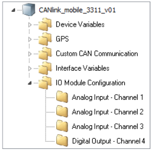 Figure 46. Input / Output Context Menu
Output Function
Define the settings for the output function under IO MODULE CONFIGURATION > DIGITAL OUTPUT - CHANNEL 4.
-
Select the object DIGITAL OUTPUT - CHANNEL 4.
-
In the CHANNEL CONFIGURATION list, select the configuration ON–OFF DIGITAL OUTPUT.
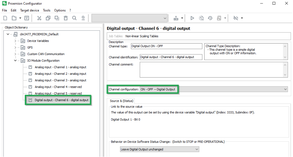 Figure 47. On - Off Digital Output
The following variables are available:
| Variable | Function |
|---|---|
CHANNEL CONFIGURATION |
Enable and disable the digital output. |
BEHAVIOR ON DEVICE SOFTWARE STATUS CHANGE |
Behavior on CANopen Mode STOP or PREOPERATIONAL. |
5.7.4. Battery
Some types of the device are equipped with an integrated battery. The DEVICE VARIABLES > BATTERY object dictionary group contains the following variables:
| Variable | Function |
|---|---|
BATTERY - CHARGE LEVEL |
Current charge level (in |
BATTERY - VOLTAGE |
Measured voltage (in |
BATTERY - CYCLE COUNT |
Number of charge cycles so far |
BATTERY - STATE OF HEALTH VALUE |
Probable remaining capacity relative to nominal capacity (in |
BATTERY - TIME TO EMPTY |
Expected remaining time until full discharge (in |
BATTERY - FULL CHARGE CAPACITY |
Probable capacity if fully charged (in |
BATTERY - CURRENT |
Current to or from the battery |
BATTERY - TEMPERATURE |
Current temperature (in |
|
5.7.5. Operation Time Counter
The device is equipped with an internal operation time counter.
The OPERATION TIME TOTAL object belongs to the DEVICE VARIABLES > I/O, SENSORS, DIAGNOSIS object dictionary group.
The operation time counter cannot be reset. The operation time counter runs as soon as the device is in Standard mode (not Sleep mode).
For detailed information on creating objects, see Creating Object Dictionary Groups and Objects.
5.7.6. Power Management
To protect the device from damage and data loss, a correct wiring and configuration of the power management settings is mandatory. The main purpose of the power management settings is that the device has a safe shutdown before the supply voltage (terminal 30/31) is disconnected.
The required variables belong to the DEVICE VARIABLES > POWER MANAGEMENT object dictionary group. For detailed information on creating objects, see Creating Object Dictionary Groups and Objects.
The following subsections provide an overview of the individual power management functions.
|
Wake up of the device is possible when at least one of following condition is fulfilled: - The IO - Clamp 15 (Ignition) State is at level high (> 6 V)- A CAN message is present at the CAN 1 or CAN 3 interface - The Power Management - Acceleration Sensor Wake-up Force is enabled and the configured threshold is exceeded - The Power Management - Cyclic Wake-up Time is enabled and the configured time is elapsed |
Power Management - Shutdown Delay Time
The Power Management - Shutdown Delay Time is required for the terminal 15 monitoring. After recognizing ignition input (terminal 15) and CAN off-state, the device will continue operating for the specified time and then go to sleep mode.
| The terminal 15 monitoring is only active if the value for the shutdown delay time is > 0 |
| Make sure that there are no CAN messages present on the CAN bus anymore before the Shutdown Delay Time is elapsed. Otherwise, the device would either not switch to sleep mode or immediately wake up. |
You can enable the Power Management - Shutdown Delay Time as follows:
-
Ensure that terminal 15 voltage from the machine is connected to the terminal 15 (input ignition signal) pin at the CANlink mobile device. See Switching the Device On/Off
-
Open the latest device configuration with the Proemion Configurator software.
-
Add the device variable Power Management – Shutdown Delay Time to your configuration.
-
Write the desired time in seconds into the parameter value input field.
The configured shutdown delay time should not be too short. It must be ensured that there is enough time for the device to finish its internal jobs, complete the latest clf file and transmit the file to the DataPlatform. -
Save the updated configuration file with a new Device Configuration Version String.
-
Write the updated configuration to the device.
-
Perform a reset of the device.
-
Check if the new power management settings are applied correctly.
Power Management - CAN sleep Time
The Power Management - CAN sleep Time is to be used when the device should be automatically set to sleep mode in case that there is none of the configured CAN messages received by the device within a specified time period.
| To set the device to sleep mode by the device variable Power Management - CAN sleep Time, the IO - Terminal 15 (Ignition) State must be low. |
You can enable the Power Management - CAN sleep Time as follows:
-
Open the latest device configuration with the Proemion Configurator software
-
Add the device variable Power Management - CAN sleep Time to your configuration
-
Write the desired time in milliseconds into the parameter value input field.
-
Save the updated configuration file with a new Device Configuration Version String.
-
Write the updated configuration to the device.
-
Perform a reset of the device.
-
Check if the new power management settings are applied correctly.
Power Management - Time to Sleep
The Power Management – Time to Sleep is used when the device needs to be set to sleep mode by a connected controller with additional power management logic functionality.
| Power Management - Time to Sleep is a volatile device variable and therefore considered as a one-time function. |
| The device will only enter sleep mode when the terminal 15 is at level low and no configured CAN message is left on the connected CAN bus. |
| While the countdown timer for Power Management – Time to Sleep is active, there is no reception and transmission of CAN messages possible |
You can trigger the Time to Sleep by the controller as follows:
-
Ensure that the terminal 15 is at level low
-
Ensure that configured CAN message are not present on the connected CAN bus.
-
Write the desired count down time in seconds via your controller and a CANopen SDO message to Object Index
0x3333, SubIndex0x08,UInt8.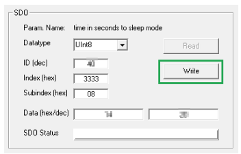 Figure 48. CANopen SDO
 -
Check that the device is set to sleep mode after the specified time is elapsed.
Power Management - Acceleration Sensor Wake-up Force
When the internal accelerometer detects an acceleration force higher than the configured value, the device automatically wakes up from sleep mode.
You can enable the Acceleration Sensor Wake-up Forc eas follows:
-
Open the latest device configuration with the Proemion Configurator software.
-
Add the device variable Power Management - Acceleration Sensor Wake-up Force to your configuration.
-
Write the acceleration force into the parameter value input field.
The lowest possible value for the acceleration force is 1.2 g.
Lower values are impractical due to the amount of false positives. -
Save the updated configuration file with a new Device Configuration Version String.
-
Write the updated configuration to the device.
-
Perform a reset of the device.
-
Check if the new power management settings are applied correctly.
Power Management - Cyclic Wake-up Time
When in sleep mode, the device will wake up from sleep mode automatically after the configured time period.
You can enable the Power Management - Cyclic Wake-up Time as follows:
-
Open the latest device configuration with the Proemion Configurator software
-
Add the device variable Power Management - Cyclic Wake-up Time to your configuration
-
Write the desired time for the cyclic wake-up in seconds into the parameter value input field.
The minimum possible value for the cyclic wake-up time is 120 seconds.
Lower values should not be used. -
Save the updated configuration file with a new Device Configuration Version String.
-
Write the updated configuration to the device.
-
Perform a reset of the device
-
Check if the new power management settings are applied correctly.
Power Management - Deep Sleep Flag
The use of Power Management - Deep Sleep Flag is especially recommended for devices with internal battery and additional wake up flags configured. This function was implemented to avoid that the device wakes up during storage time and transport and hence the battery gets discharged.
| With deep sleep mode enabled, the device will ignore the configured wakeup flags such as cyclic wake up or acceleration force. |
| Power Management - Deep Sleep Flag is a volatile device variable and therefore considered as a one-time function. |
Wake up of the device is possible when at least one of following condition is fulfilled:
-
Rising edge on IO - Terminal30 Voltage
-
The IO - Terminal 15(Ignition) State is at level
high(> 6 V) -
A CAN message is present at the CAN1 or CAN 3 interface
You can set the device into deep sleep mode before transport as follows:
-
Open the latest device configuration with the Proemion Configurator software.
-
Add the device variable Power Management – Deep Sleep Flag to your configuration.
-
Write the value 0x01 into the parameter value input field of the device variable Power Management – Deep SleepFlag to enable the deep sleep mode
-
Add the device variable Power Management – Time to Sleep to your configuration.
-
Define a value for the countdown time in seconds to sleep mode in the parameter value input field.
-
Ensure that there are no CAN messages left on the CAN bus.
-
Ensure that the terminal 15 is at level low.
-
Write the updated configuration to the device.
-
Wait for the specified time until the device is set to deep sleep mode.
-
Verify that the device does not wake up by the configured wake-up flags such as acceleration force or cyclic wake-up time.
GeoFence / GeoLeash
GeoFence Mode
The device is provided with a geofence monitoring function. This allows you to monitor whether the device is located inside or outside a pre-defined “fenced” area and when the device crosses the fence.
There are three ways to define the fence:
-
Define center and radius of a circle. The center of the circle is defined as a fixed point.
-
Define center and radius of a circle. The current position on enabling the function is used as the center of the circle.
-
Two opposite points are defined for a rectangle. The variables belong to the DEVICE VARIABLES > INTERNAL GEOFENCE object dictionary group.
| Variable | Function |
|---|---|
GEOFENCE - MODE |
|
GEOFENCE - COORDINATE 1 > LONGITUDE |
Longitude for center of the circle or first corner of the rectangle |
GEOFENCE - COORDINATE 1 > LATITUDE |
Latitude for center of the circle or first corner of the rectangle |
GEOFENCE - COORDINATE 2 > LONGITUDE / RADIUS |
GeoFence Mode Circle: Radius of the circle |
GEOFENCE - COORDINATE 2 > LATITUDE |
Latitude for the second corner of the rectangle |
GeoFence Status
The GeoFence status can be used to trigger an event internally. The GeoFence status is updated every 2 seconds. Every time the GeoFence status changes, the time is written to a variable.
The variables belong to the object dictionary group DEVICE VARIABLES.
| Variable | Function |
|---|---|
GEOFENCE STATUS |
|
GEOFENCE - STATUS CHANGE UTC TIME |
Time of GeoFence status change |
For detailed information on creating objects, see Creating Object Dictionary Groups and Objects.
GeoLeash
The GeoLeash function enables you to monitor and display the location of the machine.
In this case, the location offset is determined by an adjustable limit value. The minimum limit value for the tolerated location offset is 100 meters.
The DataPortal can be used to activate the GeoLeash function and define the area to be monitored.
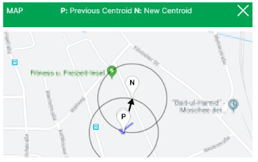
| The GeoLeash and device internal Geofence functions cannot be used simultaneously. Please be aware that the GeoLeash function must be supported by the installed firmware. In case of problems, update to the latest firmware. |
|
Further information on the GeoLeash function is available in DataPortal DataPortal User Manual > GeoLeash/ Boundary and GeoLeash (under Reporting Tools). |
5.8. Protocols and Connections
The chapter Technical Data / Protocols contains an overview of the available protocols and connections.
|
For further information on protocols and connections, refer to the Download Center. |
5.9. Safe Remote Updates Guideline
5.9.1. Introduction
Our firmware is undergoing an intensive test program with automated tests during development and an explicit test for the final release candidate. Our tests are constantly extended also by items reported from the field. Nevertheless, there is still a remaining risk of problems occurring in special cases. Considering this, we recommend the following procedure for a remote firmware or configuration update campaign.
To minimize the risk, this guideline should be followed. By following the steps, a more secure and successful update can be achieved.
|
5.9.2. Updating Steps
When planning a firmware or configuration roll-out, some steps should be considered so that the roll-out process is as safe and successful as possible. This guide is to be applied for each machine type / machine family (features: same configuration version, same initial firmware and – if applicable – same SIM card settings). By applying the guideline, the risks of errors occurring are minimized.
-
The first remote update should be carried out, if possible, on a simulator device, alternatively on an easily accessible sample machine. Check the success of this update.
-
In the second step, the remote update should be extended to a maximum of 10 machines. After rolling out the update, a check of success must be performed for each machine.
-
Subsequently, the remote update can be rolled out to a maximum of 15% of the fleet. In this case, a check of success must also be conducted after the roll-out.
-
In the last step, the rest of the fleet shall be updated.
5.9.3. Checking Success
Between the individual steps, please check randomly whether the device(s) behave(s) as expected:
-
Check the device start,shutdown behavior in the machine environment
-
Check the logged data
-
Check file transfer to your ECU
-
Check actions which you have configured
-
Check special device behaviors which you have configured
5.10. Configuration update
You can use the Proemion Configurator to load a configuration update on the device.
The configuration update can be loaded to the device via the CAN interface or the DataPlatform. The device identifies and automatically loads the new configuration.
For more detailed information on how to create a device configuration, see Customizing the demo configuration File.
5.10.1. DataPlatform
Authorization to perform a configuration update must be enabled on the DataPlatform. Generally, users with administrator rights have this authorization.
|
-
Start the Proemion Configurator software.
-
Open the corresponding configuration file (
*.DOD). -
Click on TARGET DEVICE > OBJECT DICTIONARY > DOWNLOAD > REMOTE DOWNLOAD - ALL ENTRIES or click on the arrow in the toolbar next to the DOWNLOAD ALL ENTRIES symbol.
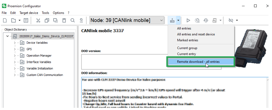 Figure 50. Configuration Update
✓ The REMOTE CONFIGURATION DOWNLOAD TO TARGET(S) window opens.
-
Click on the SELECT DEVICES button in the window REMOTE CONFIGURATION DOWNLOAD TO TARGET(S) window.
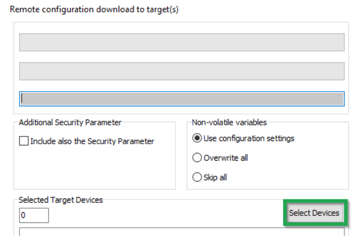 Figure 51. Configuration Update - Targets
✓ The SELECT DEVICES window opens.
-
Enter your DataPlatform user credentials in the SELECT DEVICES window.
-
Click on the LOGIN button.
-
Select the device.
-
Click on the OK button.
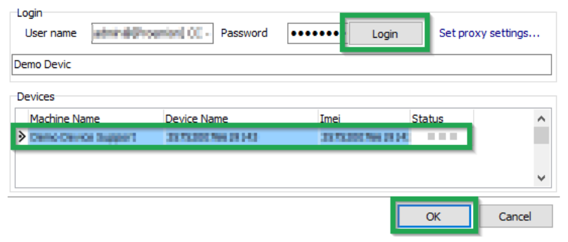 Figure 52. Configuration Update - Select Devices
NOTICE
Loss of connection due to incorrect parameters.
The online connection may be lost due to incorrect provider parameters. In most cases, it is not necessary to update the security variables, so this should be avoided.
* Before every update of the security variables, check the provider parameters.
* Refer to Safe Remote Updates Guideline and follow the recommended update process. -
Click on the START button in the REMOTE CONFIGURATION DOWNLOAD TO TARGET(S) window.
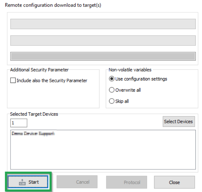 Figure 53. Configuration Update - Download to Target
✓ The following warning appears. The user is warned against downloading untested configuration files.
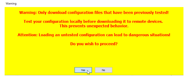 Figure 54. Configuration Update - Download Warning
 -
Click on the YES button.
✓ The configuration update download starts automatically as soon as the device is online. The download can take several minutes.
✓ The device recognizes the configuration file and saves it to its internal memory.
✓ The device LEDs light up in a certain sequence.INFORMATION
For more information on the LED status indications, see Indicator Elements.
-
Check the DOD version and the DOD activation time in the Communication unit details display of the DataPortal.
✓ The new Config Version with Timestamp will be displayed in the Communication unit details after the next connection of the device.
✓ An update log will appear in the file download section of the DataPlatform.
UpdteLog.txt after a successful configuration update<LogFileVersion>: 1.0 <BEGIN>: 1607604003 <actSW>: Fw 7.3.0 <actBL>: Bl 9.2 <actDOD>: Proemion File Size: 20763 Received configuration file CONFIGURATION DOWNLOAD COMPLETE AFTER 1 ATTEMPT(s). <newSW>: Fw 7.3.0 <newBL>: Bl 9.2 <newDOD>: CLM Demo Device V2.2.8 <END>: 1607604082
UpdteLog.txt after a failed configuration update (e.g. due to an incompatible type)<LogFileVersion>: 1.0 <BEGIN>: 1607604996 <actSW>: Fw 7.3.0 <actBL>: Bl 9.2 <actDOD>: CLM Demo Device V2.2.8 File Size: 2497 Received configuration file ERROR: Job 0 (0x1018:0x2) -0x3337 is not equal to 0x5301 ERROR: Job 0 (0x1018:0x2) -0x3337 is not equal to 0x5301 ERROR: Job 0 (0x1018:0x2) -0x3337 is not equal to 0x5301 ERROR: ABORT CONFIGURATION DOWNLOAD AFTER 3 ATTEMPTS! <newSW>: Fw 7.3.0 <newBL>: Bl 9.2 <newDOD>: CLM Demo Device V2.2.8 <END>: 1607605139
5.10.2. CAN
You can perform a configuration update using the CAN interface.
To be able to load the configuration file to the device, the device must be connected via a CAN-USB port to a PC on which the configuration file is saved.
-
Connect the device to a PC. See Connecting the Device to the PC.
-
Load the configuration to the device. See Loading the Configuration to the Device via CAN Interface.
✓ You have completed the configuration update.
5.11. Firmware update
You can load a firmware update to the device by remote maintenance via the DataPlatform, the CAN interface or the micro-USB interface (Type A connector).
|
|
|
The firmware can be downloaded from our Document Library or Download Center |
| In case of problems, the Connectivity Check utility can be used to check the connectivity of our software tools with our services from your site’s network. |
5.11.1. DataPlatform
To be able to load the firmware update (*.bin) on the device using the remote maintenance feature via the DataPlatform, the Proemion Firmware Programmer software must be installed on a PC and the firmware update stored.
The authorization to perform the remote firmware update must be enabled on the DataPlatform. Usually, users with administrator rights have this authorization.
|
-
Start the Proemion Firmware Programmer software.
-
Click on FILE > OPEN in the menu and navigate to the memory path for the firmware update (
*.bin).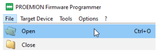 Figure 55. Firmware Update - Open Firmware File
 -
Select the firmware update (*.BIN) and click on the OPEN button.
-
In the COMMUNICATION PATH field, select the CONNECTION VIA INTERNET (N DEVICES) interface from the list.
-
Click on the SELECT DEVICES button.
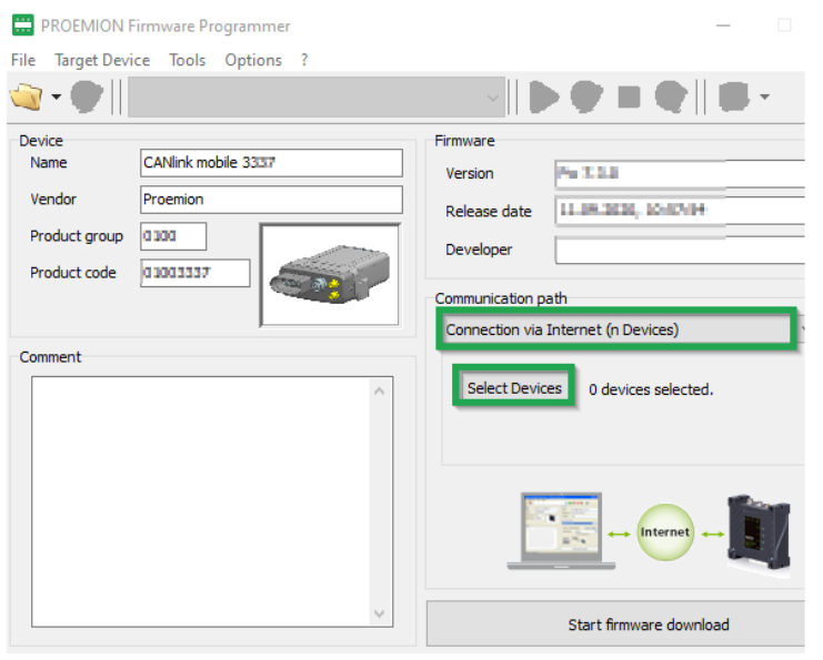 Figure 56. Firmware Update - Communication Path
✓ The SELECT DEVICES window opens.
-
If the list is empty, click on the SETTINGS button.
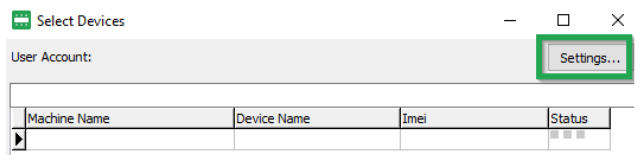 Figure 57. Firmware Update - Select Devices
✓ The COMMUNICATION SETTINGS window opens.
-
In the COMMUNICATION GATEWAY field, navigate to the GATEWAY DEVICE list and select the device CANLINK MOBILE.
-
Enter your DataPlatform user credentials in the SYSTEM ACCESS field.
-
Click on the OK button to save the settings.
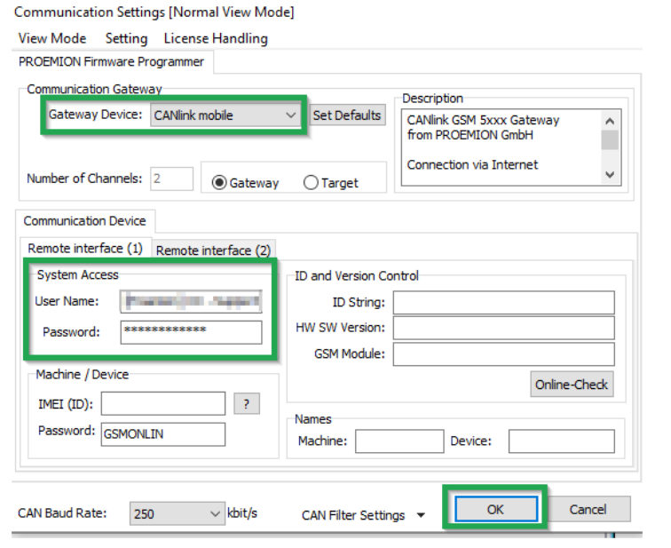 Figure 58. Firmware Update - Communications Settings
 -
Select the device in the SELECT DEVICES window. By pressing <CTRL> while clicking, you can select several devices.
-
Click on the OK button.
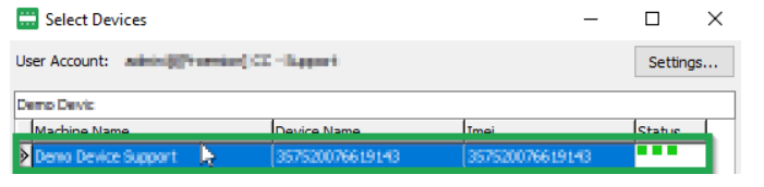 Figure 59. Firmware Update - Select Devices
 -
The following warning appears.
It points out that the device type and the firmware version will not be verified.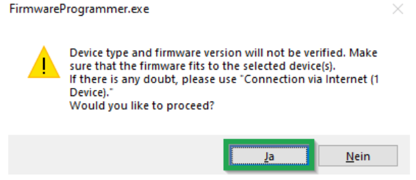 Figure 60. Firmware Update - Warning
 -
Click on the YES button.
-
Click on the START FIRMWARE DOWNLOAD button.
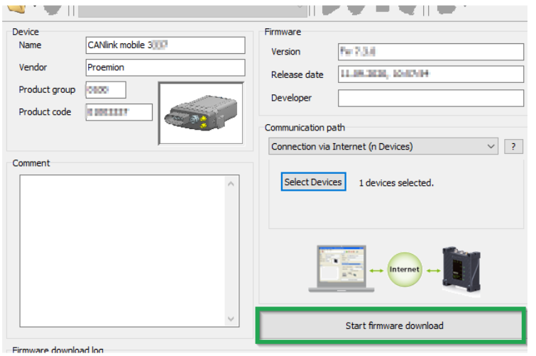
✓ The firmware files are uploaded to the DataPlatform.
✓ The following message will appear in Firmware download log when the update file has been transferred to the DataPlatform:
Connecting to webservice...
Preparing firmware...
[1/1] Uploading Firmware to machine xxxxxx...
[1/1] ...done
The firmware is available on remote server now. It will be transferred now, when logging mode is active or the next time when the device(s) connect to the server (There is no firmware update possible while realtime session or device offline).
✓ The download of the firmware files to the device memory starts automatically as soon as the device is online.
✓ During the firmware update, the LEDs light up in a certain sequence.
|
✓ The device is restarted.
✓ After the restart, the device uses the updated firmware version.
✓ An update log will appear in the file download section of the DataPlatform
UpdteLog.txt after a successful firmware update<BEGIN>: 1607594397 <actSW>: Fw 7.2.0 <actBL>: Bl 9.2 <actDOD>: CLM Demo Device V2.2.10 File Size: 477176 Received firmware file Received bin file Receiving Update for Controller 1 Received firmware file correct <newSW>: Fw 7.3.0 <newBL>: Bl 9.2 <newDOD>: CLM Demo Device V2.2.10 <END>: 1607595030
<LogFileVersion>: 1.0
<BEGIN>: 1607598855
<actSW>: Fw 7.3.0
<actBL>: Bl 9.2
<actDOD>: Proemion
File Size: 301892
Received firmware file
ERROR: Update aborted: invalid file format.
<newSW>: Fw 7.3.0
<newBL>: Bl 9.2
<newDOD>: Proemion
<END>: 1607599393
|
You can find a tutorial on how to install the firmware to the device in the download section of our website. See Service and Support. |
5.11.2. CAN
In order to load the firmware update (*.bin) on the device via the CAN interface, the device must be connected to a PC via a CAN-USB connection. The Proemion Firmware Programmer software must be installed on the PC and the firmware update stored.
-
Connect the device to a PC. See Connecting the Device to the PC.
-
Start the Proemion Firmware Programmer software.
-
Click on FILE > OPEN in the menu and navigate to the memory path for the firmware update (*.BIN).
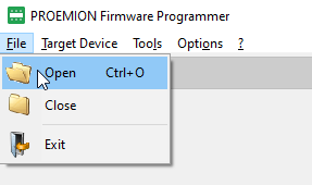 Figure 62. Firmware Update - Open Firmware File
 -
In the Open FwBin window, select the firmware update (
*.bin) and click on the OPEN button. -
In the main window, click on OPTIONS > COMMUNICATION SETTINGS in the menu.
✓ The COMMUNICATION SETTINGS window opens:
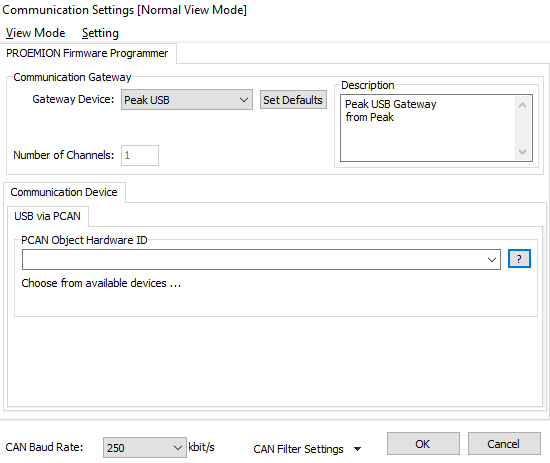 Figure 63. Firmware Update - Communication Settings
 -
In the COMMUNICATION GATEWAY section, in the GATEWAY DEVICE field select the device PEAK USB.
-
In the Communication Device section, select the PCAN Object Hardware ID.
-
At the bottom of the Communication Settings window, check for the correct CAN baud rate. The default CAN baud rate is 250 kbit/s.
-
Click OK to save the settings.
You return to the main window: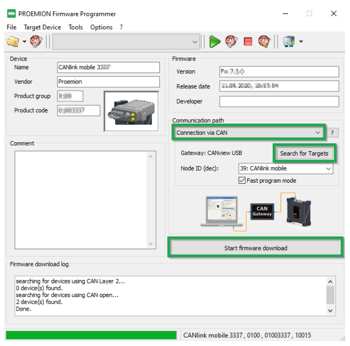 Figure 64. Firmware Update - Progress
 -
In the list in the COMMUNICATION PATH field, select the interface CONNECTION VIA CAN.
-
Click on the SEARCH FOR TARGETS button.
✓ The device’s node ID is adopted.
-
The device’s node ID is adopted.
-
Start firmware download.
-
Wait until the update is finished.
|
✓ During the firmware update, the LEDs light up green in the same sequence.
✓ In the field FIRMWARE DOWNLOAD LOG, the message FIRMWARE DOWNLOADED SUCCESSFULLY appears when the firmware update is complete.
✓ The device restarts automatically.
✓ After the restart, the device uses the updated firmware version.
|
You can find a tutorial on how to install the firmware to the device in the download section of our website. See Service and Support. |
5.11.3. Micro-USB
In order to load the firmware update (*.bin) on the device via the micro-USB interface, the device must be connected to a PC via a USB connection. The Proemion Firmware Programmer software must be installed on the PC and the firmware update stored.
If you use the USB cable USB A-Micro USB A, 1.8 -2 m USB cable (part number 136000199), the device automatically starts in Bootloader mode.
|
-
Connect the device to a PC with the cable USB cable, USB A-Micro USB A, 1.8 –2m.
-
Connect the device to the power supply grid with the cable CLM3 start cable, 6 open, 2 dsub, 1 pw, 2 m and the power supply unit from the launch kit.
 Figure 65. Connecting the CANlink mobile 3000 to a PC
NOTICE
If connected with a USB cable, USB A-Micro USB A, 1.8 -2 m cable, the device automatically starts in Bootloader mode. The LEDs do not light up. In the USB-Controller field in the Device Manager, the device is shown as "STM Device in DFU Mode".
-
Start the Proemion Firmware Programmer software.
-
Click on FILE > OPEN in the menu and navigate to the memory path for the firmware update (
*.bin). -
Select the firmware update (
*.bin) and click on the OPEN button. -
In the list in the COMMUNICATION PATH field, select the interface CONNECTION VIA USB.
-
In the list in the DEVICE field, select RM DEVICE.
-
Click on the Start Firmware Download button.
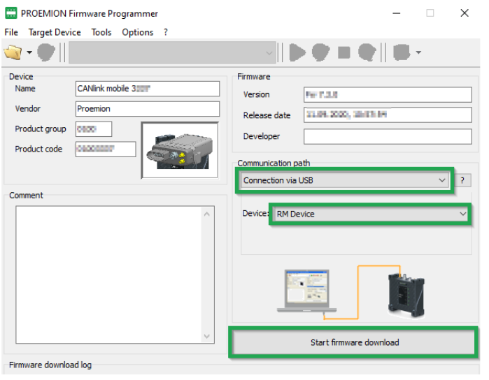 Figure 66. Start Firmware Download
 -
Wait until the update is finished.
NOTICE
Device defect due to power failure.
Destroyed file system on the device. Repairs necessary by Proemion.
* Do not disconnect the device from the power supply until the process has been completed.+
✓ During the firmware update, the LEDs light up green in the same sequence.
✓ In the field FIRMWARE DOWNLOAD LOG, the message FIRMWARE DOWNLOADED SUCCESSFULLY appears when the firmware update is complete. -
Disconnect the device from the PC.
-
Disconnect from the power supply e.g., using the main plug connector.
-
For types with integrated Battery: Press the Reset button on the main plug connector using a suitable tool (1 mm diameter).
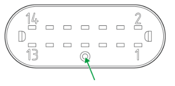 Figure 67. Connector Reset Button
NOTICE
Use of the Reset button on the main plug connector is only necessary for types with an integrated battery.
✓ The device is restarted.
✓ After the restart, the device uses the updated firmware version.
|
You can find a tutorial on how to install the firmware to the device in the download section of our website. See Service and Support. |
5.12. Diagnosis via Micro-USB Port
For diagnosis purposes, you can connect the device to a PC directly via the micro-USB (type B) cable and record a debug log by using the CANlink mobile 3000 DeviceAnalyzer software.
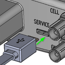
|
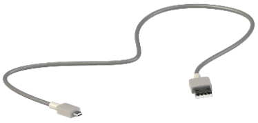
|
|
5.12.1. Recording the Debug Log
|
-
Install the
CANlink mobile 3000 DeviceAnalyzer Setup.exesoftware and the CANlink mobile 3000 USB driver from the Download Center. -
Connect the device to a PC with the cable USB cable, USB-A on micro-USB-B, 1.6 m.
-
Connect the device to the power supply.
-
Follow the instruction from the CANlink mobile 3000 DeviceAnalyzer software manual in Chapter 3.2 Debug Log.
-
If necessary, you can send the logfile
*.glogto the Support department for further evaluation.
|
5.13. Device Reset
Performing a device reset returns the device to the original settings.
|
|
|
5.13.1. Device Reset via CAN
The following table provides an overview of the various reset options available which can be triggered via the CAN interface:
| Function | Index | Subindex | Description |
|---|---|---|---|
Revert to Factory Configuration |
|
|
The factory configuration is restored. All logged data is deleted. |
Delete All Log Files |
|
|
All logged data stored on the device is deleted. |
Revert to Firmware Defaults Remote |
|
|
The standard configuration of the current firmware is restored. |
Revert to Firmware Defaults plus Format Remote |
|
|
The standard configuration of the current firmware is restored. |
Revert to Firmware Defaults Local |
|
|
The standard configuration of the current firmware is restored. |
|
In order to complete a device reset via the CAN interface, a CANopen software (e.g. CANopen Magic) and a communication gateway (e.g. PCAN-USB - CAN/USB Interface) are required.
The CANopen software writes the value 0x64616F6C to the CANopen object index 0x1011 to trigger a specific reset variant.
In the following example, the device reset using the sub-index 0x65 (Revert to Firmware Defaults Local) is shown:
-
Connect the device to a PC. See Chapter Connecting the Device to the PC.
-
Start the selected CANopen software.
-
Perform the required steps in the CANopen software to write the value
0x64616F6Cto the object index,0x1011subindex0x65. -
Write the value to the device’s object directory.
-
Wait until the device sends the CANopen bootup message to the IDs
0x727and0x728.
✓ The device reverts to the firmware defaults (object 0x1011; 0x65).
✓ The ON LED lights up green.
✓ The STATUS LED lights up blue.
✓ The device has adopted the firmware defaults (CAN Baud Rate 250 kbit/s, CANopen Node ID 39 etc.).
|
|
You can find a tutorial on how to perform a device reset in the download section of our website. See also Chapter Service and Support. |
5.13.2. Device Reset via USB Connector Cable/Diagnosis
The device reset via the USB connector cable (diagnosis) and the CANlink mobile 3000 DeviceAnalyzer software is another option to perform a reset of the CANlink mobile device. Please refer to the CANlink mobile 3000 DeviceAnalyzer software manual at the Download Center.
|
Follow the instructions from chapter 3.4 Resets of the CANlink mobile 3000 DeviceAnalyzer software manual.
5.13.3. Device Reset via the Start Cable
The device reset via the start cable corresponds with the function Revert to Firmware Default Local index 0x1011 sub-index 0x65.
|
-
Connect the device to the power supply grid with the cable CLM3 start cable, 6 open, 2 dsub, 1 pw, 2 m and the power supply unit from the launch kit.
-
Slide the switch on the D-Sub connector (CAN1) towards the SUB-D connection
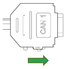
✓ The LED on the D-Sub connector (CAN1) lights up red.
-
Wait until both LEDs on the device light up orange.
-
Slide the switch on the D-Sub connector (CAN1) toward the LED.
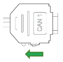
NOTICE
Device defect due to power failure.
Destroyed file system on the device. Repairs necessary by Proemion.
- Do not disconnect the device from the power supply until the process has been completed.
✓ The device reverts to the firmware defaults (object 0x1011; 0x65).
✓ The ON LED lights up green.
✓ The STATUS LED lights up blue.
✓ The device has adopted the firmware defaults (CAN Baud Rate 250 kbit/s, CANopen Node ID 39 etc.).
|
|
|
You can find a tutorial on how to perform a device reset in the download section of our website. See also Chapter Service and Support. |
6. Troubleshooting
This chapter contains information on solving problems and on maintenance.
|
|
6.1. Remedies
| Problem | Possible cause |
|---|---|
Device does not function. |
Check the power supply via the main plug connector (terminal 30, terminal 31, terminal 15). |
Device does not receive CAN messages |
Check the CAN connection and the configuration of the CAN messages. Check whether the bus terminating resistor is correctly mounted. |
Device does not receive GNSS signals. |
Check the antenna connection and cable for damage. Position the antenna or the device so that it directly points to the sky. |
Device does not receive mobile radio signal. |
Check the antenna connection and cable for damage. Check the eSIM configuration in the eSIM - Specials object dictionary. Position the antenna or the device so that it directly points to the sky. |
Device does not log data. |
Check the CAN baud rate in the configuration. Check in the configuration whether the device is in "Operational" mode. Check the logging configuration. |
Device with integrated battery does not initialize after switching on or firmware update. |
Use a suitable tool to press the reset button on the main plug connector to restart the device. |
6.1.1. Support Request
|
If you do not find the solution to your problem in this manual, please contact our support team. See chapter Service and Support.
The support team requires the following information to help you:
-
Connect the USB Connector Cable - Diagnostic to your PC and create a device log with the CANlink mobile 3000 DeviceAnalyzer software when the problem appears. While the device log is recorded, click on Restart. This will allow the support team to also evaluate the initialization phase of the device.
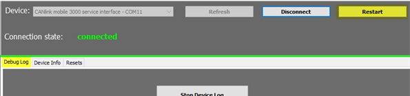
-
Read out all device and security variables with the CANlink mobile 3000 DeviceAnalyzer.
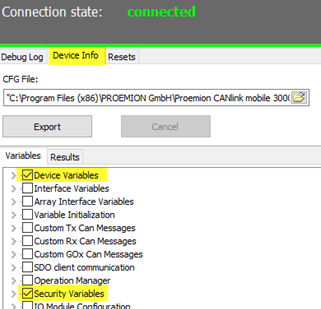
-
What is the condition of the status LED after the restart was triggered by the DeviceAnalyzer software? If possible, create a video of the status LEDs in addition to the device log including the restart.
-
Send the device log, the video of the status LEDs and the required output about the device and security variables by creating a ticket at Support.
6.1.2. Connection Problems to the DataPlatform
If the device cannot establish a connection to the DataPlatform, check the following:
-
Has the configuration been correctly loaded on the device? See chapter Configuration update.
-
Are the device LEDs lighting up correctly? See Chapter Indicator elements (LED).
-
Are the contract and device settings in the DataPortal correct?
-
Are the configured mobile communication parameters within the device configuration correct?
You can find more information in the following chapter.
DataPortal
Check that the contract and device settings in the DataPortal are correct.
-
Login at the DataPortal.
-
Click on Administration.
-
Click on Overview.
-
Click on COMMUNICATION UNITS.
-
Enable the checkbox Include sub-organizations.
-
Enter the device name or machine name in the corresponding search box.
-
Check in the machine column if the correct/expected machine name is displayed.
-
Check the Organization column if the device is allocated to the correct organization unit.
-
Click on the DETAILS button of the corresponding communication unit.
✓ The detail view of the selected device is displayed.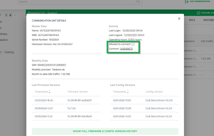
-
Click on the contract number from the contract field to check in the contract overview if the device has a valid contract.
✓ The contracts view of the selected device is displayed. -
Click on Details.
✓ The contract details of the selected contract are opened.
-
Check the contract details for the correct settings.
-
The settings for the communication unit and machine can also be checked in this window.
Device Configuration
Check if the mobile communication parameters in the Proemion Configurator are correct.
The variables belong to the Security Variables group.
You may use the tables below as a copy/paste template for the information to the support team.
-
Establish a physical CAN connection with a supported gateway device.
-
Start the Proemion Configurator software.
-
Select the correct gateway device and com port in the communication settings.
-
Open the corresponding device configuration file.
-
Open the tab Specials.
-
Read out the configured Security Variables according to the table below and make a note for later reference. If there are security variables missing in the used device configuration, they can be added with a right mouse click onto the tree element
Security Variables.Table 64. Security Variables Security Variable Default Value with Proemion eSIM card Read value Remote Server Address
gateway.proemion.comRemote Server Port
61200Enable encrypted data transfer
1Online Mode Handling
1[E-SIM] SIM PIN
empty
[E-SIM] Roaming Handling
1[E-SIM] Operator Selection Mode
0[E-SIM] Operator Selection Code
0[E-SIM] DNS1
[empty][E-SIM] DNS2
[empty][E-SIM] ISP Username
[empty][E-SIM] ISP Password
[empty][E-SIM] APN
internet.m2mportal.de[E-SIM] SMS Service Center Address
+491710760000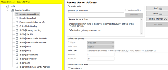
-
Open the Application tab in your configuration.
-
Read out the device variables according to the table below. If there are device variables missing in the used configuration, they can be added by right mouse click onto the object dictionary group Device Variables.
Table 65. Device Variables Device Variable Default Value Read value Mobile - Disconnect Mode (embedded SIM)
1Mobile - Signal Quality
(read-only)
Mobile - Network State
(read-only)
Mobile - Modem Result
(read-only)
Mobile - Network Mode Select
0
Mobile - Network Mode Current
(read-only)
Mobile - Antenna Status
(read-only)
Mobile - failure reconnect delay
30
Mobile - State Machine current state code
(read-only)
Mobile - State Machine Error Code
(read-only)
Mobile - CMS Error Number
(read-only)
Mobile - CME Error Number
(read-only)
Mobile - SIM pin error flag
(read-only)
Mobile - Engine IMEI Number
(read-only)
Mobile - SIM Card ID (ICCID)
(read-only)
Mobile - Active Network Provider
(read-only)
Mobile - Local IP Address
(read-only)
Mobile - Engine Version
(read-only)
Mobile - Maximum Cellular Receive Delay
5000
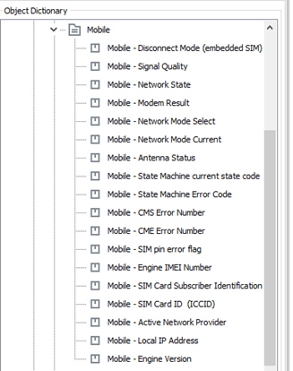
-
Provide the tables with the read-out values to the Proemion support.
|
|
If you do not find the solution to your problem in this manual, please contact our Proemion support. See also Chapter Service and Support. |
6.2. Maintenance
Check all connectors for a firm connection regularly.
Check the state of the integrated battery. If the battery is totally discharged or has reached the maximum number of 500 charge cycles, please contact the Proemion support.
See chapter Service and Support.
|
|
|
6.3. Cleaning
|
To avoid damage caused by liquid ingress, no high-pressure cleaners may be used for cleaning. In order to remove contamination, you should also avoid using jet water if possible. Instead, use a damp cleaning cloth with a solvent-free and acid-free cleaning liquid.

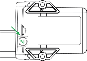

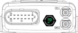
7. Packaging and Transport
This chapter contains information on packing and transportation.
|
|
|
8. Disposal
This chapter contains information on correct disposal.
|
8.1. Regulations in the European Union
|
According to the Directive on Waste Electrical and Electronic Equipment (WEEE), the device must not be disposed of in household waste. The device contains a lithium-polymer battery which can contain toxic and polluting heavy metals. Take the device to a collection point for waste electrical and electronic equipment for correct disposal. |

|
9. Annex
This chapter contains technical data and certificates.
9.1. Technical Drawings
|
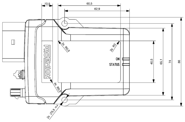
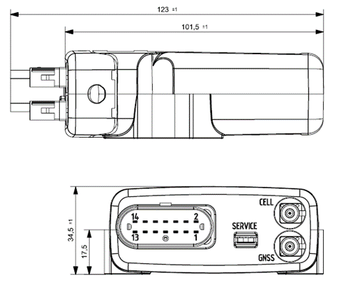
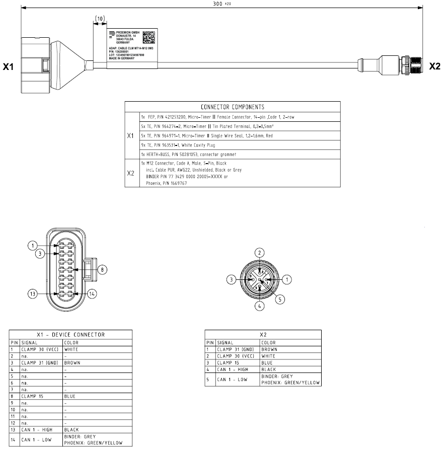
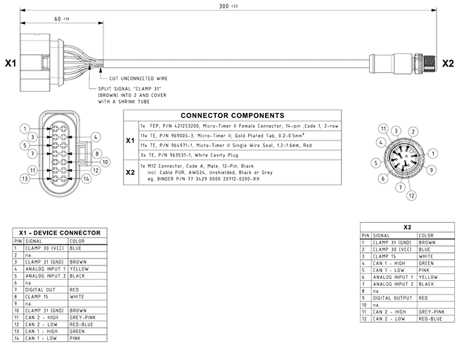
9.2. Technical Data
This chapter contains information on the technical data of the device.
9.2.1. Mechanical
| Parameter | Value |
|---|---|
Dimensions width/height/depth [mm] |
86 / 123 / 35 |
Color |
Black |
Protection class |
IP6K7 |
Temperature range |
Standard mode: -40 °C … +80 °C / -40 °F … +176 °F |
Weight |
3311: 160 g |
Standard housing material |
PA 66/6 - FR |
Pressure equalizing membrane |
Yes |
Resistance of the housing material to chemicals |
The housing material of the device was successfully tested against the following liquids in accordance with the standard EN ISO 175. |
9.2.2. Electrical
| Parameter | Value |
|---|---|
Supply voltage range terminal 30 DC |
12 / 24 V ⎓ ±50 % |
Battery voltage, battery operation |
3.7 V (internal) |
Power consumption, with terminal 30 supply (24 V) |
< 250 mA (standard mode) |
Power consumption, battery operation (3.7 V) |
< 600 mA (standard mode) |
Average power consumption |
< 4 W |
Controller |
Arm Cortex M4 168 Mhz |
Memory expansion Program Flash |
1 MB |
Data Flash memory expansion |
16 MB (Types 33xx) |
Memory expansion FRAM |
8 kB |
Memory expansion SRAM |
760 kB |
LEDs |
2 LEDs, RGB (red/green/blue) |
Keys |
Types 3337, 3377, 3477, 3577: |
Battery |
Lithium-polymer, 3.7 V; 1.15 Ah; 4.225 Wh |
RTC with back-up capacitor |
Back-up time: 48 h at 25 °C |
9.2.3. Interfaces
| Parameter | Value |
|---|---|
CAN (number, ISO) |
CAN1: ISO 11898-2 |
CAN specification |
2.0 A/B |
Max. CAN baud rate |
1000 kbit/s, 5 Mbit/s at CAN3 with firmware which supports CAN-FD |
Mobile radio |
33xx: GSM/UMTS |
Mobile radio frequency range |
Types 33xx: |
Mobile radio transmission rate |
- GPRS upload: 85.6 kbit/s |
Maximum mobile radio transmission power |
CANlink mobile 33xx, 34xx: |
Satellite systems supported |
GPS/QZSS L1 C/A, GLONASS L10F BeiDou B1I, Galileo E1B/C @ Frequency Band 1559 – 1608 MHz |
Bluetooth Standard |
Types 3333, 3337, 3373, 3377, 3477, 3577: |
Bluetooth frequency range |
Bluetooth Classic: 2.402 - 2.480 GHz in 79 channels |
Bluetooth transmission rate |
Bluetooth Classic: up to 3 Mbit/s |
WLAN Standard |
Types 3333, 3337, 3373, 3377, 3477, 3577 |
WLAN frequency range |
- 2.400 - 2.4835 GHz (IEEE 802.11 b/g/n) in 13 channels |
WLAN transmission rate |
IEEE 802.11a: to 54 Mbit/s |
WLAN encryption |
Types 3333, 3337, 3373, 3377, 3477, 3577 |
USB |
1 micro-USB type A/B (12 MBit/s), 2.0 full speed, self-powered device |
Digital OUT |
1 digital output |
Analog IN |
3 analog inputs |
Terminal 15 |
1 digital / analog input |
Analog IN (reset) |
2 analog factory setting inputs |
Terminal 30 |
1 analog input |
Acceleration sensor |
Measurement range: ±16 g |
Gyro sensor / Rate of rotation sensor |
Measurement range: ±250 °/s |
Temperature sensor |
Measurement range: -40 °C … +85 °C / -40 °F … +185 °F |
9.3. Certification and Qualification
The device has been certified and qualified according to the valid standards and regulations.
For more information on the corresponding approval tests, please contact Support.
|
Proemion GmbH hereby declares that the CANlink® mobile 3000 wireless communication system complies with the provisions in Directive 2014/53/EU.
|
The full text of the declaration of conformity is available at our website Declaration of Conformity. |
E1
ECE Regulation No. 10 (version 5)
Approval number: 10R-05 8436
Version: 11.0.988