Assembly Drawings
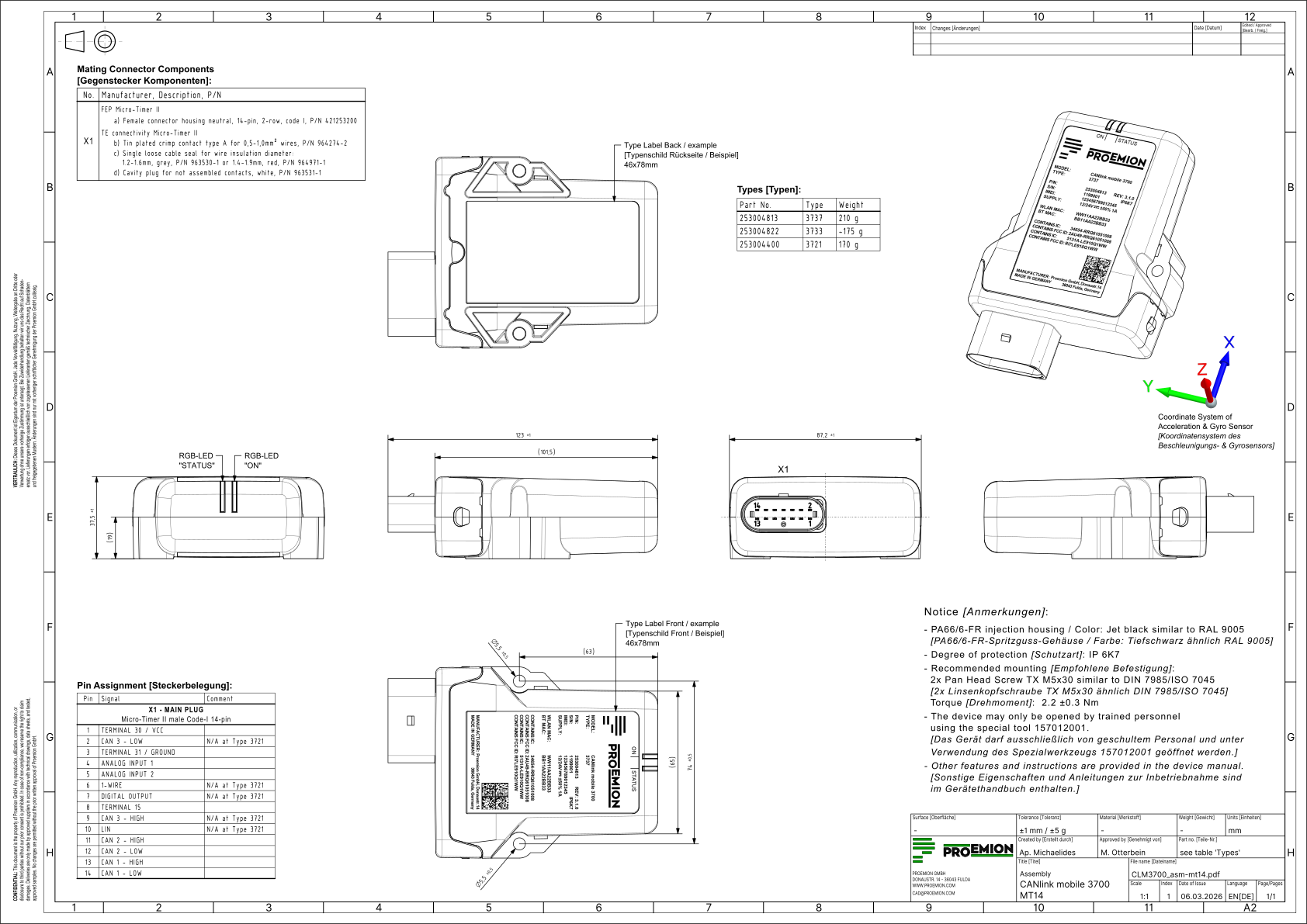
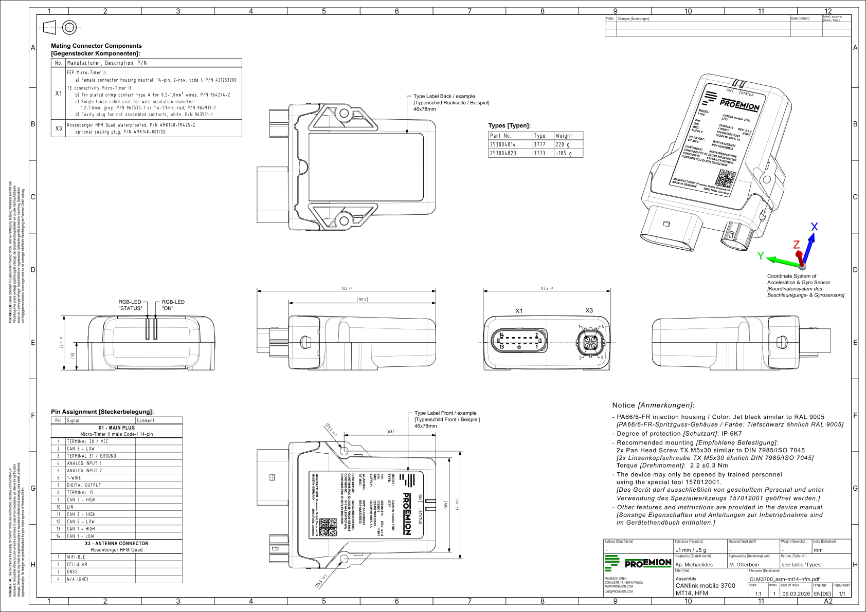
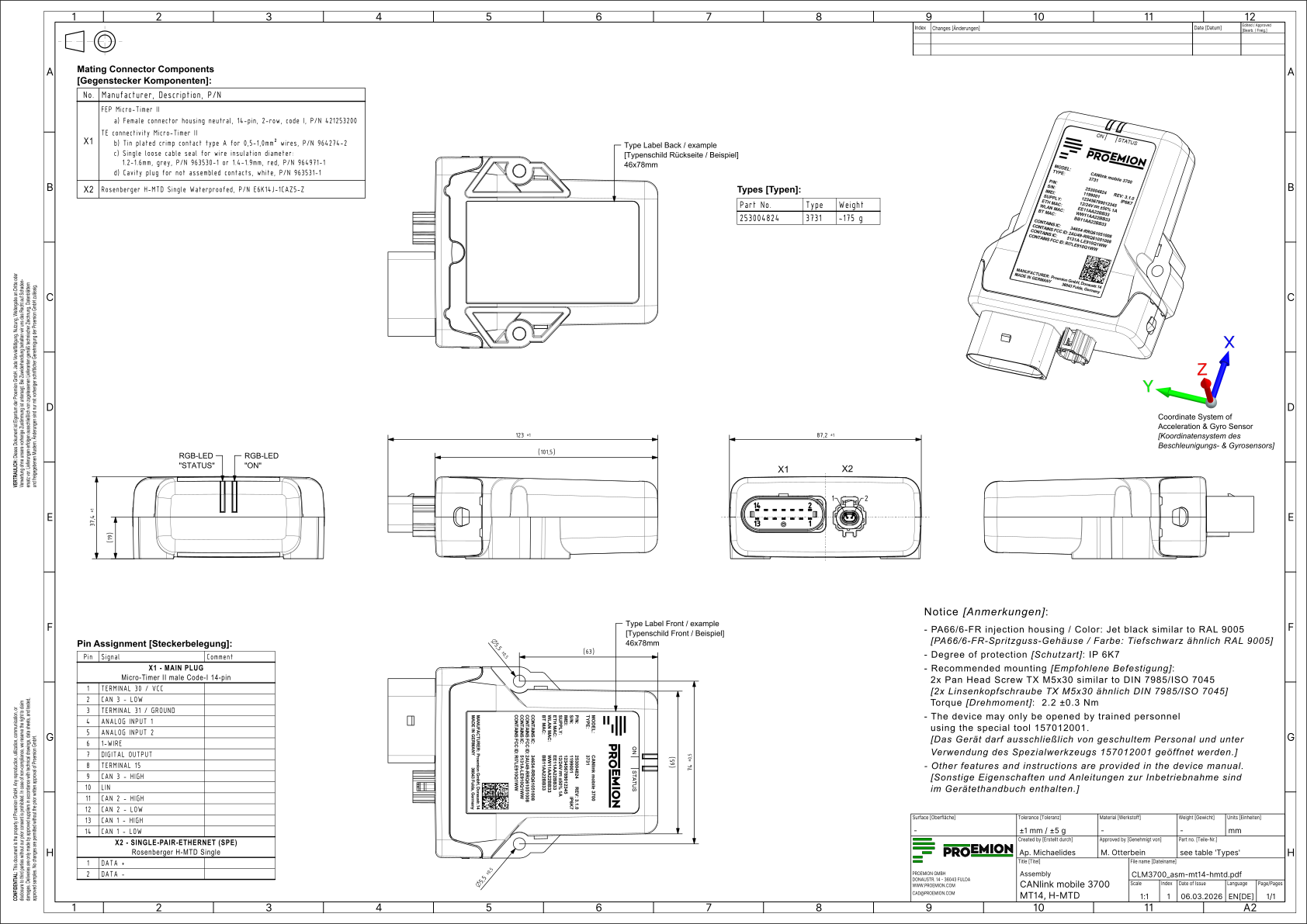
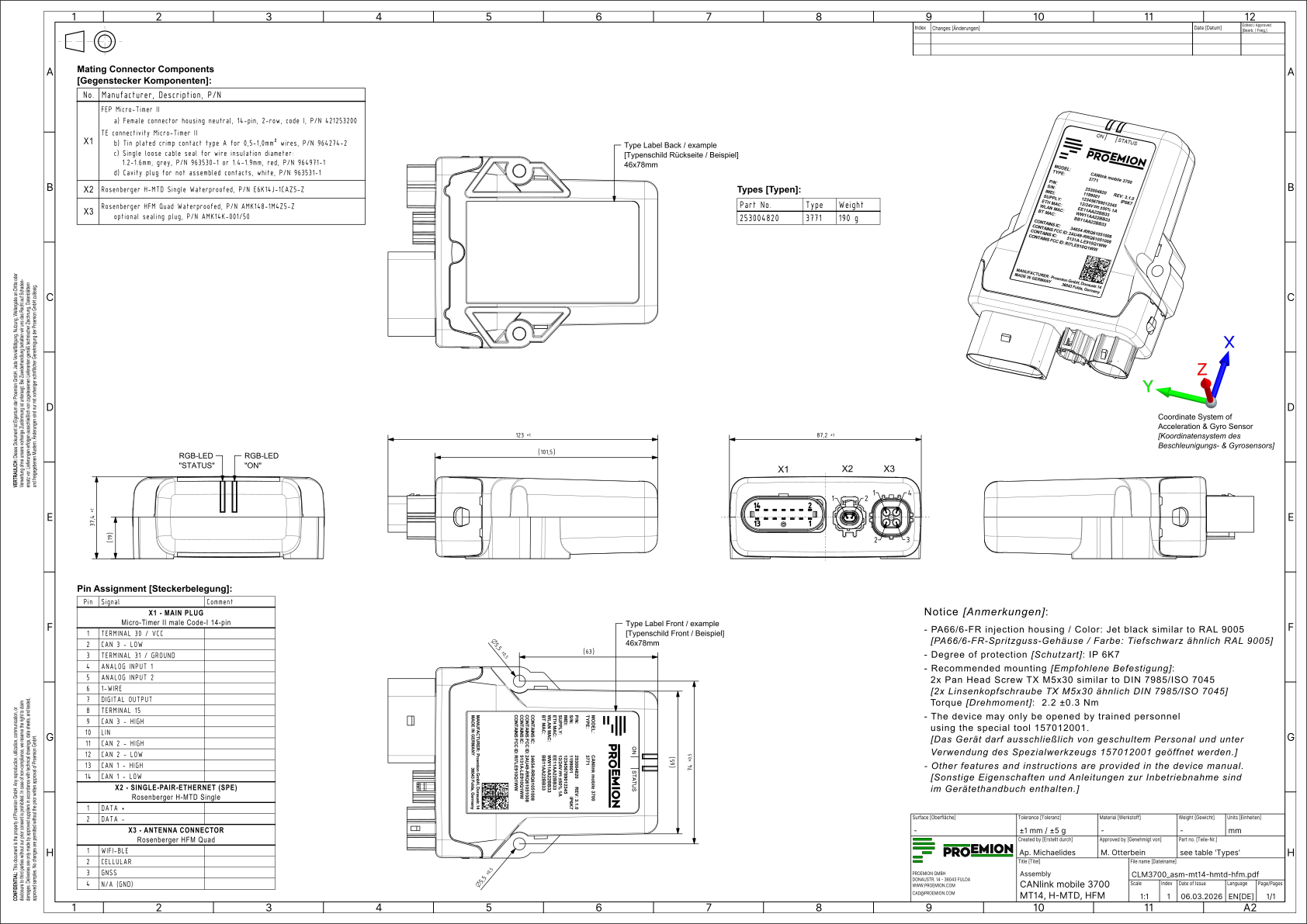
This chapter contains the assembly drawings of the four available housing forms of the CANlink® mobile 3700, including their dimensions, connector interface, and pin assignment.
All housing forms include a Main Plug Connector for power and CAN bus communication.
Housing Form A - No Additional Connectors
Housing Form B - External Antenna Connector
Housing Form C - Ethernet Connector
Housing Form D - Ethernet and Antenna Connectors
PDF files of the assembly drawings are available in the Download Center under:
01_Proemion_Devices > 01_CANlink mobile 3700 > 01_Documentation > Drawings