|

Proemion Basic Tracker Teltonika FMC234
1. Preamble
1.1. Legal Notice
All brands and trademarks named in this document and possibly protected by third-party rights are subject without limitation to the terms of the valid trademark law and intellectual property rights of their respective registered owner.
You can find a list of the free-source and open-source software as well as copyright notes, license texts and, if applicable, the relevant source code on our website under the link: Free & Open Source Software
Observe all local and regional laws and provisions as well as the safety instructions contained in this document.
1.2. Contact
Proemion GmbH
Donaustr. 14
36043 Fulda, Germany
Phone: +49 661 9490-0
Fax: +49 661 9490-111
info@proemion.com
Proemion Corp.
US Subsidiary
241 Taylor St., Suite 301
Dayton, Ohio 45402, USA
Phone: +1 937 558 2211
Fax: +1 937 641 8787
info-dayton@proemion.com
Proemion Ltd.
373 Gangnam-daero Seocho-gu
Seoul, 06621, South Korea
Phone: +82 2 6080 9490
Fax: +82 504 484 9490
info-seoul@proemion.com
Website: Proemion
1.3. About This Manual
This document is part of the product and provides important information on the intended use, safety, installation, and operation of the devices described below. The document is intended for qualified technicians and electricians with advanced knowledge in electrical engineering and field bus systems, allowing them to estimate the risks and hazards of operating the device and to integrate it into systems with components of other manufacturers.
1.3.1. Safety Levels
The safety levels have the following meanings:
|
Severe injury or death. Probability: very high |
|
Severe injury or death. Probability: possible |
|
Slight or medium injury. Probability: possible |
|
Property damage. |
1.3.2. Symbols and formatting
The following symbols and formatting help you recognize the purpose of the
paragraphs:
|
|
|
|
|
|
| Symbol | Description |
|---|---|
|
Application options for the devices described. |
|
Indicates references to other documents, websites, etc. |
|
Description of different types. Data and descriptions that only apply to certain types are either covered in separate chapters or marked with the symbol shown here. |


2. About the Device
This chapter provides an overview of the Teltonika FMC234, the devices' operating elements and functions as well as the intended use of the devices.
Additionally, it provides an overview of the available Models/Types, i.e. the predecessor Teltonika FMM230 and its certificates and technical data.
The FMC234, the successor of the FMM230, has a higher battery capacity.
For more detailed information, see Chapter Annex.
2.1. Important Device Information
2.1.1. Device Elements
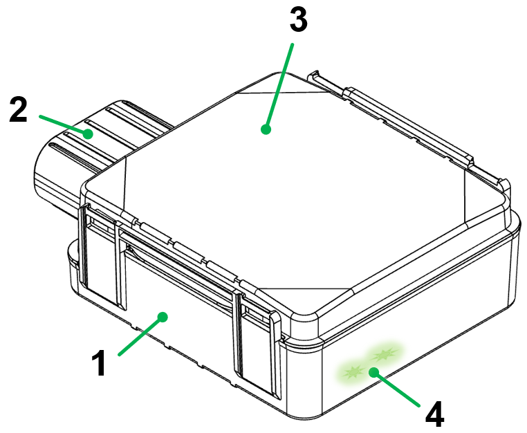
| # | Item |
|---|---|
1 |
Housing |
2 |
Main plug connector |
3 |
Housing cover with imprinted type label information |
4 |
LED Indication |
|
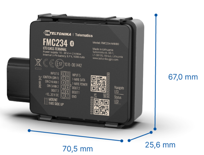
2.1.2. Type Label
The type label on top provides the following information:
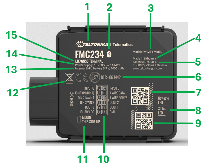
| # | Item |
|---|---|
1 |
Manufacturer |
2 |
Bluetooth symbol |
3 |
Model designation |
4 |
Country of origin |
5 |
Manufacturer address |
6 |
Certification marks |
7 |
IMEI number + QR Code |
8 |
LED indication |
9 |
Serial number + QR code |
10 |
Pin assignment of main plug connector |
11 |
Mounting orientation |
12 |
Disposal symbol |
13 |
Specification of internal battery |
14 |
Specification of power supply |
15 |
Hardware version and info of used technology |
|
|
2.1.3. Intended Use
-
The device provides access to the GNSS position, the operating hours of the machine, the latest terminal 15 (ignition signal) status and the charging level of the internal battery.
|
-
The Basic Tracker can be used in environments that require protection class IP67.
|
-
Only use the device within the permitted temperature range and the other parameters specified in the Technical Data.
Any use other than that described under “Intended use” is considered unintended use. -
The device is equipped with low capacity rechargeable battery to ensure a safe shutdown when the power supply voltage is disconnected. See also Technical Data.
The integrated battery has a limited lifetime. Please note that the battery cannot be replaced in the field. In the event of a defective battery, visit the Support website and contact the technical support department by using our Support Form. The device is not designed for permanent battery operation. Its battery has a very limited capacity. For this reason the device shall be connected to the permanent power supply voltage (terminal 30) so that it can also operate if the machine was powered off. The device will go to sleep mode with a minimal power consumption when DIN 1 (terminal 15) changed to status low and only turns on to send a regular low frequency position update.
MISUSE
The device does not comply with Directive 2014/34/EU and may not be used in potentially explosive areas.
QUALIFIED PERSONNEL
The device must only be put into operation by qualified technicians and electricians with advanced knowledge of electrical engineering.
The specialist personnel must know the contents of this manual and always have access to it.
|
|
2.1.4. Conformity
For further details regarding the conformity, please refer to FMC234 Certification & Approvals, resp. FMM230 Certification & Approvals.
2.2. Device Functions
The Basic Tracker is a tracking unit with GNSS and GSM connectivity, capable of capturing geo-locations, ignition status and machine operating hours. When the device is connected to the Proemion DataPlatform, it cyclically transmits the collected data over the GSM network.
The main features are:
-
4G (LTE Cat 1) network coverage (Fallback to 2G)
-
GPS module for locating the device
-
IP67 protection class
-
Temperature range -20° - +85° C
-
Backup battery
-
Bluetooth connectivity*
-
3 digital inputs, 1 negative input, 2 impulse inputs, 2 analog inputs, CAN adapter input, 3 digital outputs*
| *Not all available features are supported by the default Device Configuration. |
2.3. Available Models
The available models differ according to the provided table below.
| Model | Part number | Battery capacity |
|---|---|---|
FMC234 |
257001045 |
1000 mAh |
FMM230 |
257001032 |
170 mAh |
2.4. Service and Support
The latest versions of the drivers, software, firmware, and documentation are available in our Document Library.
Do you need help or want to report a bug?
Visit Proemion for more information, or raise a ticket at Support.
2.4.1. Firmware Updates and Support
|
3. Safety Information
This chapter contains important information on how to avoid life-threatening situations and injuries and how to prevent product damage.
3.1. Safety Instructions
| In addition to the safety instructions below, the manufacturer’s must be followed, see FMC234 Safety information, resp. FMM230 Safety information. |
|
|
|
|
|
|
|
|
|
|
|
3.4. Warranty and Liability
Proemion assumes no liability for defects caused by normal wear, external influences and incorrect installation, operation or maintenance. This also applies if the customer or a third party modifies the devices, any accessories, or the software without permission from Proemion.
4. Functionality and Features
This chapter contains information on device functionality and features. It provides details of the operating modes, connectors, cables, pin assignments, interfaces and indicator elements.
4.1. Functions
The Basic Tracker is a water and dust resistant tracking terminal with LTE CAT M1 network coverage including 2G (GSM) fallback compatibility.
It comes equipped with internal GNSS, LTE antennas and backup battery.
Depending on the operating mode, the Basic Tracker records and transmits the following data to the DataPlatform and DataPortal.
| Signal Name | Signal Key |
|---|---|
Machine Position (latitude) |
value.common.machine.geo.latitude |
Machine Position (longitude) |
value.common.machine.geo.longitude |
Ignition state |
value.common.cu.sensors.ignition.state |
Estimated Operating Hours Total (based on ignition = ON) |
value.common.machine.hours.operation.total |
Estimated Total Distance Travelled |
value.common.machine.distance.total |
Towing Detected |
value.common.machine.towing.detected |
Supply Voltage Modem |
value.common.machine.battery.potential |
Modem Disconnection From Power Supply Detected |
value.common.cu.unplug.detected |
Internal Battery - State of charge |
value.common.cu.battery.stateofcharge |
Internal Battery - Voltage |
value.common.cu.battery.voltage |
Cellular Signal Quality (1-5) |
value.common.cu.signal.quality |
4.2. Connectors
The device is equipped with the following connectors:
-
1x main plug connector
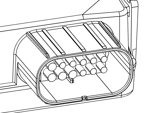
4.2.1. Main plug connector
Use the main plug connector to connect the device to power supply and terminal 15 (ignition key) voltage. For the pin assignment of the main plug connector, see the following overview.
| Pin | Designation | Description | Comment |
|---|---|---|---|
1 |
VCC |
Power supply (10…30 V DC) |
Power supply |
2 |
DOUT 3 |
Digital output, channel 3. Open collector output. Max. 0.5 A DC |
unused in Proemion application |
3 |
AIN 2 / DIN 3 |
Analog input, channel 2. Input range: 0…30 V DC / Digital input, channel 3 |
unused in Proemion application |
4 |
DIN 2-N/AIN1 |
Digital input, channel 2, Negative input, Analog input, channel 1, Input range: 0…30 V DC |
unused in Proemion application |
5 |
DIN 1 |
Digital input, channel 1 |
used for the "working" signal (e.g. TERMINAL 15 / IGNITION) |
6 |
INPUT 6 |
TX EXT (LVCAN – TX) |
unused in Proemion application |
7 |
GND |
Ground |
Power supply |
8 |
DOUT 1 |
Digital output, channel 1. Open collector output. Max. 0.5 A DC |
unused in Proemion application |
9 |
DOUT 2 |
Digital output, channel 2. Open collector output. Max. 0.5 A DC |
unused in Proemion application |
10 |
1WIRE POWER |
+3.8 V output for 1–Wire devices |
unused in Proemion application |
11 |
1WIRE DATA |
Data for 1–Wire devices |
unused in Proemion application |
12 |
INPUT 5 |
RX EXT (LVCAN - RX) |
unused in Proemion application |
|
4.3. Cables
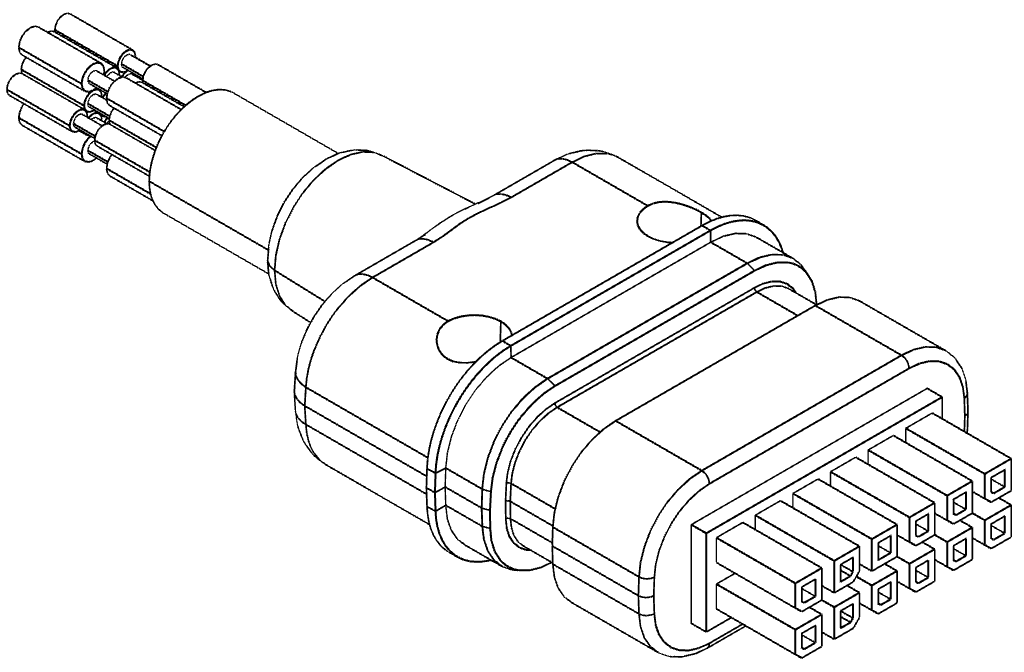
4.3.1. Starter Cable / Main Plug Connector
The pin assignment and wire colours of the main plug connector cable delivered with the device is provided here.
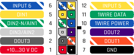
| Pin | Designation | Color | Description |
|---|---|---|---|
1 |
VCC |
Red |
Power supply (10…30 V DC) |
2 |
DOUT 3 |
Dark Grey |
Digital output, channel 3. Open collector output. Max. 0.5 A DC |
3 |
AIN 2 / DIN 3 |
Light Grey |
Analog input, channel 2. Input range: 0…30 V DC / Digital input, channel 3 |
4 |
DIN 2-N/AIN1 |
Green-White |
Digital input, channel 2, Negative input, Analog input, channel 1, Input range: 0…30 V DC |
5 |
DIN 1 |
Yellow |
"Working" signal (e.g. TERMINAL 15 / IGNITION) |
6 |
INPUT 6 |
Blue-White |
TX EXT (LVCAN – TX) |
7 |
GND |
Black |
Ground |
8 |
DOUT 1 |
Orange-White |
Digital output, channel 1. Open collector output. Max. 0.5 A DC |
9 |
DOUT 2 |
Dark Purple |
Digital output, channel 2. Open collector output. Max. 0.5 A DC |
10 |
1WIRE POWER |
Blue |
+3.8 V output for 1–Wire devices |
11 |
1WIRE DATA |
Green |
Data for 1–Wire devices |
12 |
INPUT 5 |
Yellow-White |
RX EXT (LVCAN - RX) |
| Please make sure that the unused wires are properly isolated from each other. |
4.3.2. Custom Cable for Main Plug
When creating a customized cable harness for the system integration of the Basic Tracker, some important recommendations for the setup of the main plug connector and cable must be considered.
|
|
| Further information on the type of connector can be provided on request by using the Support Form. |
4.3.3. Cable Management
|
|
-
Protect the connector and the cable with sufficient covers and cable tubing.
4.4. Battery
The device is equipped with a 1000 mAh Li-ion rechargeable 3.7 V battery to ensure a safe shutdown when the power supply voltage is disconnected. See also Technical Data.
| The integrated battery has a limited lifetime. Please note that the battery cannot be replaced in the field. In the event of a defective battery, visit the Support website and contact the technical support department by using our Support Form. |
| The device is not designed for permanent battery operation. Its battery has a very limited capacity. For this reason the device shall be connected to the permanent power supply voltage (terminal 30) so that it can also operate if the machine was powered off. The device will go to sleep mode with a minimal power consumption when DIN 1 (terminal 15) changed to status low and only turns on to send a regular low frequency position update. |
4.5. LED Indication
The device is equipped with two green LEDs to indicate the GNSS status and the operating status. See also FMC234 LED Status, resp. FMM230 LED Status.
| Due to the fact that there is no additional light guide for the internal LEDs in the housing, the status of the LEDs may not be recognizable in very bright ambient light. For a clearer visibility of the LEDs please use a dark cloth or a similar tool to shade the area around the device. |
5. Getting Started
This chapter describes the first steps that are required for the initial commissioning of the device. Furthermore, it contains useful information on how to connect and mount the device.
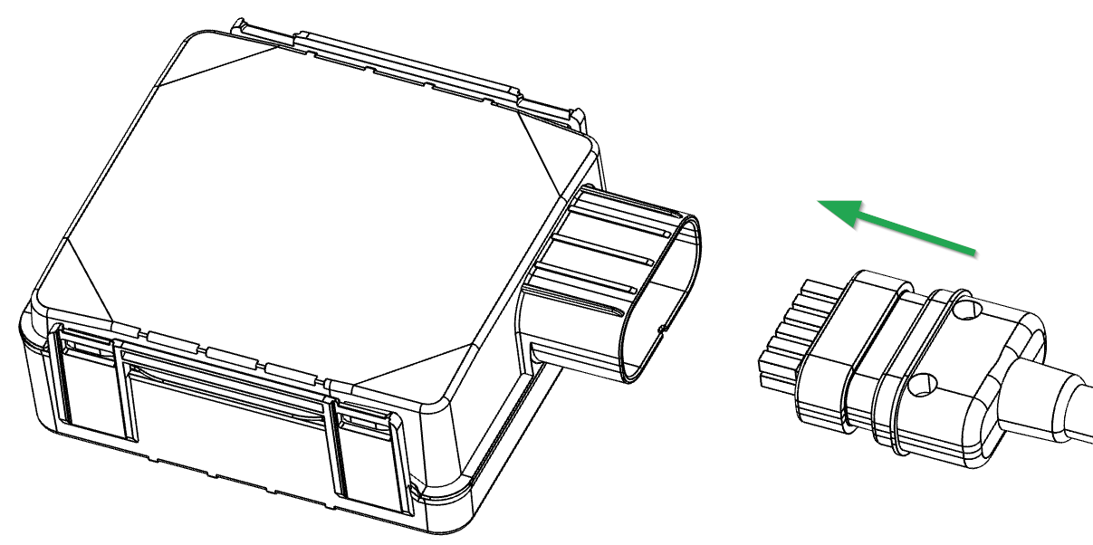
5.1. Connecting the Device
-
Connect the device to the power supply. Refer to the pin layout of Main plug connector.
-
If available, connect the machine’s ignition signal. Refer to the pin layout of Main plug connector.
-
Mount the device according to chapter Hardware installation
-
Protect the cable with sufficient strain relief and tubing.
|
|
|
If you have any questions or anything is unclear, please contact our support before getting started. See chapter Service and Support. |
5.1.1. Connect device according to operation conditions
The following section describes how to connect the Basic Tracker device according to the machine’s operation conditions.
As the Basic tracker calculates the operating hours by a "high" signal on the input pin (DIN1), it is recommended to connect this input to any signal line that indicates the "working" or "operation" state of the machine. This could be a combustion engine’s ignition (Terminal 15) signal or the generator output.
There may be machines with different operation conditions.
-
Machines with permanent battery supply voltage and ignition or "working" signal
-
Machines with permanent battery supply voltage but without ignition or "working" signal
-
Machines that just provide supply voltage during operation (e.g. without a starter battery but with a generator)
The recommended wiring for the three use cases are:
| Signal | Basic Tracker Connector Pin | Wire colour | Machine connection |
|---|---|---|---|
VCC |
1 |
Red |
+10…30 V permanent supply (battery) |
GND |
7 |
Black |
GND permanent supply (battery) |
DIN 1 |
5 |
Yellow |
Switched ignition or "working" signal |
| Signal | Basic Tracker Connector Pin | Wire colour | Machine connection |
|---|---|---|---|
VCC |
1 |
Red |
+10…30 V permanent supply (battery) |
GND |
7 |
Black |
GND permanent supply (battery) |
DIN 1 |
5 |
Yellow |
leave unconnected |
| Signal | Basic Tracker Connector Pin | Wire colour | Machine connection |
|---|---|---|---|
VCC |
1 |
Red |
+10…30 V supply (generator) |
GND |
7 |
Black |
GND supply (generator) |
DIN 1 |
5 |
Yellow |
+10…30 V supply (generator) |
5.2. Provisioning and Go Live
Provisioning allows you to make a machine with a Basic Tracker installed available on the DataPortal. The machine will be visible and during the process you can assign a model and change the machine name, serial number and PIN/VIN.
Go Live is the automated activation of a Basic Tracker after Provisioning. Once the CU has been activated, it is authorized to connect to the DataPlatform and transfer data.
-
Login to the DataPortal. See also Proemion DataPortal User Manual.
-
Login with your username and password.
-
Provision the Basic Tracker to make it visible on your DataPortal account as described in chapter Provisioning.
-
Use Go Live to activate the device and permit DataPortal communication.
|
|
5.3. Device Configuration
| The device is already delivered with a pre-installed configuration. A customization of the logging parameters is not possible in the field. |
There are two modes for the device’s data acquisition: On stop, Moving:
-
The
Movingmode is detected when the ignition signal is ON → Data is recorded every 5 minutes and transferred every 60 minutes -
The
On stop(ignition signal has status low) data is recorded and transferred every 6 hours.
There is an Ignition On Counter which counts the time in seconds, when the ignition signal is ON. This value is transferred with the default datasets and displayed as Estimated Machine Operating Hours.
Additionally, a Towing Detection is implemented.
This function detects a movement of the device (machine) while it is in the “On stop” state.
While the towing event is detected, the operation and recording mode changes to “Moving”.
The device activates the towing function when following conditions are met:
-
Ignition (configured Ignition Source) is OFF, i.e.
-
when the terminals 15 or 30 is off or,
-
both terminals are off at the same time or,
-
only terminal 15 is off while terminal 30 is on.
-
-
Activation Timeout is reached.
When the Towing function is engaged, the device monitors the accelerometer data.
If the acceleration Threshold or Angle reach configured values for a configured Duration, and Ignition is still OFF for a period of time that is longer than Event Timeout, then an event is generated.
The Towing function will be reactivated after the device detects a change of Ignition state from ON to OFF.
| Parameter | Unit | Description |
|---|---|---|
GPS latitude |
° |
Machine position. |
GPS longitude |
° |
Machine position. |
Ignition state |
The latest status of the terminal 15 (ignition key) is displayed. Ignition Off = 0 and Ignition Off = 1. |
|
Estimated Operating Hours Total |
hr |
Counter for the time in hours when the terminal 15 (ignition key) was at status high. |
Estimated Total Distance Travelled |
km |
Total mileage received. |
Towing Detected |
Passive movement is displayed when there was a change of GNSS position and terminal 30 or terminal 15 voltage at status low was detected. |
|
Supply Voltage Modem |
V |
The external supply voltage is displayed (terminal 30 voltage). |
Modem Disconnection From Power Supply Detected |
Indicator for disconnected terminal 30 and terminal 15 voltage. |
|
Internal Battery - State of charge |
% |
The latest level of charge of the internal battery relative to its capacity is displayed. |
Internal Battery - Voltage |
V |
The latest voltage of the internal battery is displayed. |
Cellular Signal Quality (1-5) |
Signal strength of GSM signal. Value in range 1-5. |
5.4. Hardware installation
5.4.1. Mounting the Device
Below you will find some recommendation on how to mount the device. Please also refer to the Mounting recommendations of the manufacturer.
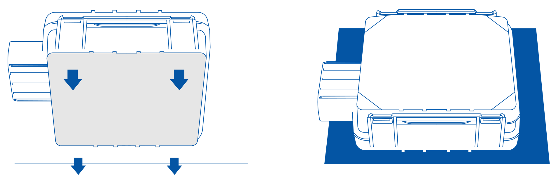
Since the internal antenna of the Basic Tracker is located on the top side, the device should be mounted with the device logo viewing to the open sky for the best device performance with not less than ¾ of metal-free area. The Basic Tracker has IP67 protection class and the best performance is reached if mounted outside of the vehicle.
The Basic Tracker can be fixed at the machine via plastic cable straps, velcro, double-sided tape or suitable glue and should be mounted with the device name view to the open sky.
| The mounting material is not included in the scope of supply. |
| As the main plug connector does not include a lock, fasten the cable harness with a suitable strain relief near the main plug connector to avoid transmitting any tension, strains, or vibrations. It must be ensured that the cable cannot be accidentally pulled out. |
| Ensure that there is a minimum bending radius of 8 times the outer diameter of the cable harness. |
| Problems with the radio connection can be caused by insufficient antenna alignment, interferences, and RF-damping labels. Do not stick RF-damping labels onto the housing of the device. |
6. Troubleshooting and maintenance
This chapter contains advice on eliminating possible errors and notes on maintenance.
6.1. Troubleshooting
| Problem | Advice |
|---|---|
Device is without any function |
Check the power supply. |
Device is stuck in sleep mode |
Check if terminal 15 and the power supply are connected. |
If you do not find the solution to your problem within this manual, please contact the support. See chapter Service and Support.
The support team requires the following information in order to help you.
-
Concise description of the problem.
-
Serial number of the device.
-
The IMEI number of the device.
Use the Support Form to provide the required device information and description of the problem.
6.2. Maintenance
-
Check all connectors for a firm connection regularly.
-
Check the housing for cracks or any other damages regularly.
-
Check the state of the integrated battery. If the battery is totally discharged or has reached the maximum number of charge cycles, please get in contact with Proemion by using the Support Form.
|
|
|
6.3. Cleaning
|
To avoid damage caused by liquid ingress, no high-pressure cleaners may be used for cleaning. In order to remove contamination, you should also avoid using jet water if possible. Instead, use a damp cleaning cloth with a solvent-free and acid-free cleaning liquid.
7. Packaging and Transport
This chapter contains information on packing and transportation.
|
8. Disposal
This chapter contains information on correct disposal.
|

9. Annex
This chapter contains technical data and certificates.
9.1. Technical Drawings
| More detailed technical drawings can be provided on request by using the Proemion Support Form. |
9.2. Technical Data
Please refer to the Technical Data FMC234, resp. Technical Data at the website of the device manufacturer.
9.3. Certification and Qualification
For all certifications and approvals, i.e. E-Mark, RoHS, REACH, etc., check the manufacturer’s page: FMC234 Certification & Approvals, resp. FMM230 Certification & Approvals.
9.4. List of supported Countries and Country Certifications
The following list shows the countries that the SIM card supports combined with countries the device has certifications for, as of September 2022.
| If your desired destination country is not on the list, contact your DataPortal representative. |
| Country / Economic Area | Certification | Cellular service coverage* |
|---|---|---|
Australia |
ACMA |
3G/4G/LTE-M |
Austria |
CE |
2G/3G/4G |
Belgium |
CE |
2G/3G/4G/LTE-M |
Bulgaria |
CE |
2G/3G/4G |
Croatia |
CE |
2G/3G/4G |
Cyprus |
CE |
2G/3G/4G |
Czech Republic |
CE |
2G/3G/4G |
Denmark |
CE |
2G/3G/4G/LTE-M |
Estonia |
CE |
2G/3G/4G |
European Union |
CE |
|
Finland |
CE |
2G/3G/4G/LTE-M |
France |
CE |
2G/3G/4G/LTE-M |
Germany |
CE |
2G/3G/4G/LTE-M |
Greece |
CE |
2G/3G/4G |
Hungary |
CE |
2G/3G/4G |
Ireland |
CE |
2G/3G/4G |
Iceland |
CE |
2G/3G/4G |
Italy |
CE |
2G/3G/4G |
Latvia |
CE |
2G/3G/4G |
Liechtenstein |
CE |
2G/3G/4G |
Lithuania |
CE |
2G/3G/4G |
Luxembourg |
CE |
2G/3G/4G/LTE-M |
Malta |
CE |
2G/3G/4G |
Montenegro |
CE |
2G/3G/4G |
Netherlands |
CE |
2G/4G/LTE-M |
Norway |
CE |
2G/3G/4G/LTE-M |
Poland |
CE |
2G/3G/4G/LTE-M |
Portugal |
CE |
2G/3G/4G |
Romania |
CE |
2G/3G/4G/LTE-M |
Switzerland |
CE |
2G/3G/4G/LTE-M |
Slovakia |
CE |
2G/3G/4G |
Slovenia |
CE |
2G/3G/4G |
Spain |
CE |
2G/3G/4G/LTE-M |
Sweden |
CE |
2G/3G/4G/LTE-M |
United Kingdom |
UKCA |
2G/3G/4G/LTE-M |
| *Depending on the cellular service availability in the respective country. |
Version: 11.0.988